Informasi Dokumen
- Penulis:
- Jeffrey O. Grady
- Sekolah: University of California San Diego
- Mata Pelajaran: System Engineering
- Topik: System Requirements Analysis Second Edition
- Tipe: book
- Tahun: 2014
- Kota: San Diego
Ringkasan Dokumen
I. Introduction
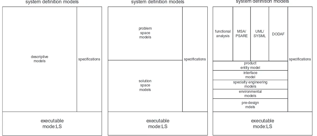
The 'System Requirements Analysis, 2nd Edition' serves as a comprehensive guide for system engineers, providing a structured approach to defining and analyzing system requirements. This edition emphasizes the importance of modeling in the requirements analysis process, advocating for the derivation of all requirements from established models. By addressing both problem-space and solution-space models, the book offers insights into managing complex systems effectively. The integration of various modeling frameworks aims to enhance operational knowledge and improve the reliability of system specifications, making it a vital resource for professionals in the field.
II. What Is a System?
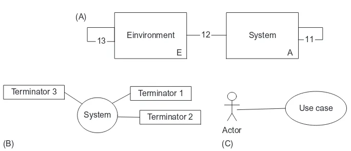
A system is defined as an organized collection of entities that interact cooperatively to achieve a common goal. This book focuses on man-made systems, which require engineering efforts to convert preplanned functions into practical solutions. The significance of systems lies in their ability to perform better than unorganized collections of objects due to purposeful interactions among their components. Understanding the relationships between system entities and their interfaces is crucial for effective system design, which this book elaborates on through various modeling techniques.
III. Types of Systems
The book categorizes systems into three types: unprecedented, precedented, and mixed. Unprecedented systems involve developing solutions without prior experience, which necessitates a structured modeling approach. Precedented systems rely on historical examples but may require new modeling efforts if previous documentation is lost. This classification underscores the need for adaptable methodologies in requirements analysis, as different systems may demand tailored approaches to ensure successful development and implementation.
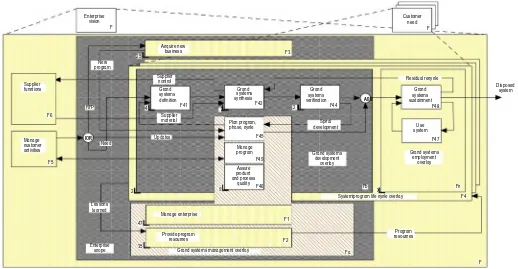
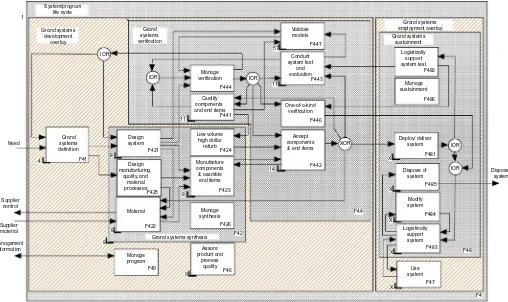
IV. Modeling Approaches
The text introduces four Universal Architecture Description Frameworks (UADFs) that guide the modeling process: functional, MSA-PSARE, UML-SysML, and an extended UPDM. Each framework provides unique strengths and methodologies for identifying system requirements and managing their development. The emphasis on modeling as a foundational element in the requirements process reinforces the book's objective of promoting effective practices in system engineering, ensuring that all requirements are traceable and derived from well-structured models.
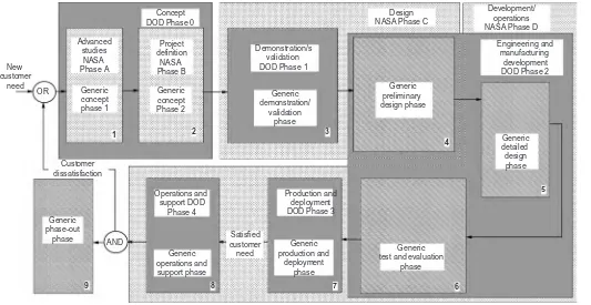
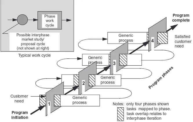
V. Importance of Requirements Analysis
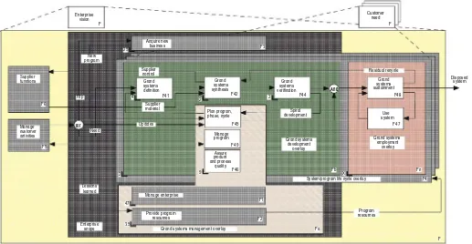
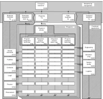
Requirements analysis is critical in system development as it lays the groundwork for successful design, procurement, and manufacturing processes. The book highlights the need for a robust management infrastructure to support requirements work, ensuring that all specifications are aligned with the overall system goals. By advocating for a disciplined approach to requirements analysis, the text aims to equip system engineers with the tools necessary to navigate complex projects and achieve desired outcomes efficiently.