Abstract—The heating coil pipe is one of the most important equipment in the thermal oil system. The pipe is located within each of the fuel tanks, which will be used as a place for thermal oil fluid flow in order to transfer heat to the fuel inside the tank. The equipment has been installed on 17500 LTDW Product Oil system, namely pipe stress analysis. This analysis was performed by using the simulation of a software, namely Caesar II with ASME B31.3 as the code standard. The result concludes that the heating coil pipes inside each fuel tank are safe to operate, which means that the allowable stress of the pipe is bigger than the which has designed actually can not withstand the pressure of the fluid that through inside it so that the pipeline eventually experiencing cracks and causing leaks. Therefore, in designing piping system, one of the requirements that must be done is pipe stress analysis.
Pipe stress analysis is conducted with the aim to ensure that the piping system can operate safely without any wreck. Pipe stress analysis can analyze the pipe’s material resistance to a fluid flow inside the pipe which can lead to corrosion and crack, can also analyze the pipe’s lifetime, and others. Some factors that can affect the pipe’s strength are stress, corrosion, and erosion.
The heating coil pipe is one of the most important equipment in the thermal oil system. This kind of pipe is located within each of the fuel tanks, which will be used as a place for thermal oil fluid flow in order to transfer heat to the fuel inside the tank. The heating coil pipes are already installed on board, but not yet tested. Meanwhile, the thermal oil system operates at high temperature, in which if not evaluated can
cause damage to the existing piping system (for example is cracking). Damage can occur because of the stress that happened in the piping system is bigger than the allowable stress of the pipe. Therefore, pipe stress analysis is needed to evaluate whether the existing heating coil pipe inside each fuel tank is able or not withstand the working pressure and working temperature of the thermal oil system.
An engineering evaluation in term of pipe stress analysis is conducted by this research. This analysis will be performed by using a software simulation, namely Caesar II with ASME B31.3 as the code standard. If the result shows that the existing heating coil pipe has a critical stress, then will be determined what method will be done to overcome or reduce the critical stress. Conversely, if the critical stress does not occur in the simulation result, then will be performed a sensitivity analysis. It is intended to find out in what case that the heating coil pipe arrangement become a failure.
Untuk menyisipkan gambar, tempatkan kursor pada titik yang dituju kemudian pilih di antara: Insert | Picture | From File atau kopi gambar ke clipboard lalu pilih Edit | Paste Special | Picture (dengan “float over text” tidak dicentang).
II. RESEARCH METHOD
A. Data Collection
Before doing the analysis, there are several data that must be known, as follows.
1) Heating Coil Pipe Data of Storage Tank Portside
The heating coil pipe data of storage tank portside will be shown in the following table.
Table 1.
Heating Coil Pipe Data of Storage Tank Portside Heating Coil Pipe Data
2) Heating Coil Pipe Data of Storage Tank Starboard The heating coil pipe data of storage tank starboard will be
Heating Coil Pipe Stress Analysis of Thermal
Oil Plant on Fuel Oil Tanks of 17500 LTDW
Product Oil Tanker
Juda Imanuel Osvaldo Panggabean, Taufik Fajar Nugroho, and Wolfgang Busse
Department of Marine Engineering, Faculty of Marine, Institut Teknologi Sepuluh Nopember
–
Hochchule Wismar
: [email protected], [email protected]
shown in the following table.
Table 2.
Heating Coil Pipe Data of Storage Tank Starboard Heating Coil Pipe Data
3) Heating Coil Pipe Data of Settling Tank
The following table will show the data of heating coil pipe inside the settling tank.
Table 3.
Heating Coil Pipe Data of Settling Tank Heating Coil Pipe Data
4) Heating Coil Pipe Data of Service Tank Portside The following table will show the data of heating coil pipe inside the service tank portside.
Table 4.
Heating Coil Pipe Data of Service Tank Portside Heating Coil Pipe Data
5) Heating Coil Pipe Data of Service Tank Starboard The heating coil pipe data of service tank starboard will be shown in the following table.
Table 5.
Heating Coil Pipe Data of Service Tank Starboard Heating Coil Pipe Data drawing of thermal oil system on MT. Parigi will be converted
first into the software which will run the stress analysis later, namely Caesar II. The following figure will show a preview of the software to be used in this research analysis.
Figure 1. Preview of CAESAR II 2014 Edition
The heating coil pipe stress analysis will be performed in two kinds of load, namely sustained load and expansion load. C. Sensitivity Analysis
Sensitivity analysis is carried out if the simulation result of existing heating coil pipe does not show any critical stress. This analysis is intended to determine the condition where the heating coil pipe inside each fuel tank will become a failure, or the allowable stress of the pipe is lower than the actual stress occurring on the system. This analysis will be done by removing one or more support that used in the pipe arrangement. Then, it will be known what effect will occur when the pipe support is removed from a piping system. This analysis is also be done by using a simulation of Caesar II.
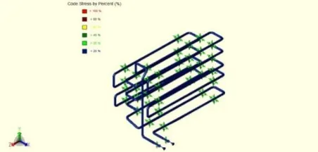
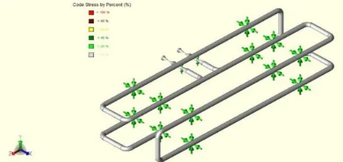
III. RESULTS AND DISCUSSION oil fluid flowing therein the heating coil is 180oC and ambient temperature inside the tank is 45oC. The following figure will show the result of pipe stress simulation in sustained load.
The figure above shows the result of sustained load simulation for heating coil inside storage tank portside is in blue color, which means that the value of sustained load is below 20% of allowable stress. The full result of simulation will be attached in this document. Allowable stress for this simulation based on ASME B31.3 is 135190,7 kPa. Maximum code stress in this simulation is 12530,5 kPa, happened at Node 80. That means the maximum stress happened is 9,3% of allowable stress.
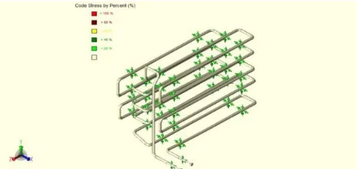
The following figure will show the result of pipe stress simulation in expansion load.
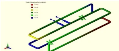
Figure 3. Expansion Load of Heating Coil Arrangement Inside Storage Tank Portside
Based on the figure above, it is known that the result of expansion load simulation for heating coil inside storage tank portside is in white metallic color, which means that the value of sustained load is below 20% of allowable stress. Allowable stress for this simulation based on ASME B31.3 is 329024,3 kPa. Maximum code stress in this simulation is 25628,9 kPa, happened at Node 79. That means the maximum stress happened is 7,8% of allowable stress.
2) Storage Tank Starboard
The fuel oil capacity of storage tank starboard is 312,26 m3 with 63,75 meters length of the heating coil. Heating coil pipe is using JIS G3459, material of SUS 316 with Nominal Diameter of 50 and Schedule 40. The temperature of thermal oil fluid flowing therein the heating coil is 180oC and ambient temperature inside the tank is 45oC. The following figure will show the result of pipe stress simulation in sustained load.
Figure 4. Sustained Load of Heating Coil Arrangement Inside Storage Tank Starboard
The figure above shows the result of sustained load simulation for heating coil inside storage tank starboard is in
blue color, which means that the value of sustained load is below 20% of allowable stress. The full result of simulation will be attached in this document. Allowable stress for this simulation based on ASME B31.3 is 135190,7 kPa. Maximum code stress in this simulation is 14336 kPa, happened at Node 468. That means the maximum stress happened is 10,6% of allowable stress.
The following figure will show the result of pipe stress simulation in expansion load.
Figure 5. Expansion Load of Heating Coil Arrangement Inside Storage Tank Starboard
Based on the figure above, it is known that the result of expansion load simulation for heating coil inside storage tank starboard is in white metallic color, which means that the value of sustained load is below 20% of allowable stress. The full result of simulation will be attached in this document. Allowable stress for this simulation based on ASME B31.3 is 335110,8 kPa. Maximum code stress in this simulation is 40062,9 kPa, happened at Node 460. That means the maximum stress happened is 12% of allowable stress.
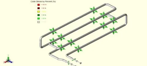
3) Settling Tank
The fuel oil capacity of settling tank is 23,74 m3 with 31,11 meters length of the heating coil. Heating coil pipe is using JIS G3459, material of SUS 316 with Nominal Diameter of 40 and Schedule 40. The temperature of thermal oil fluid flowing therein the heating coil is 180oC and ambient temperature inside the tank is 60oC. The following figure will show the result of pipe stress simulation in sustained load.
Figure 6. Sustained Load of Heating Coil Arrangement Inside Settling Tank
allowable stress. The full result of simulation will be attached in this document. Allowable stress for this simulation based on ASME B31.3 is 135190,7 kPa. Maximum code stress in this simulation is 3953,1 kPa, happened at Node 92. That means the maximum stress happened is 2,9% of allowable stress.
The following figure will show the result of pipe stress simulation in expansion load.
Figure 7. Expansion Load of Heating Coil Arrangement Inside Settling Tank
Based on the figure above, it is known that the result of expansion load simulation for heating coil inside settling tank is in white metallic color, which means that the value of sustained load is below 20% of allowable stress. The full result of simulation will be attached in this document. Allowable stress for this simulation based on ASME B31.3 is 338905,7 kPa. Maximum code stress in this simulation is 20297,7 kPa, happened at Node 90. That means the maximum stress happened is 6% of allowable stress.
4) Service Tank Portside
The fuel oil capacity of service tank portside is 23,74 m3 with 15,56 meters length of the heating coil. Heating coil pipe is using JIS G3459, material of SUS 316 with Nominal Diameter of 40 and Schedule 40. The temperature of thermal oil fluid flowing therein the heating coil is 180oC and ambient temperature inside the tank is 90oC. The following figure will show the result of pipe stress simulation in sustained load.
Figure 8. Sustained Load of Heating Coil Arrangement Inside Service Tank Portside
The figure above shows the result of sustained load simulation for heating coil inside service tank portside is in blue color, which means that the value of sustained load is below 20% of allowable stress. The full result of simulation will be attached in this document. Allowable stress for this
simulation based on ASME B31.3 is 135190,7 kPa. Maximum code stress in this simulation is 3079,7 kPa, happened at Node 191. That means the maximum stress happened is 2,3% of allowable stress.
The following figure will show the result of pipe stress simulation in expansion load.
Figure 9. Expansion Load of Heating Coil Arrangement Inside Service Tank Starboard
Based on the figure above, it is known that the result of expansion load simulation for heating coil inside service tank portside is in white metallic color, which means that the value of sustained load is below 20% of allowable stress. The full result of simulation will be attached in this document. Allowable stress for this simulation based on ASME B31.3 is 339846,3 kPa. Maximum code stress in this simulation is 19711,8 kPa, happened at Node 150. That means the maximum stress happened is 5,8% of allowable stress.
5) Service Tank Starboard
The fuel oil capacity of service tank starboard is 23,74 m3 with 15,56 meters length of the heating coil. Heating coil pipe is using JIS G3459, material of SUS 316 with Nominal Diameter of 40 and Schedule 40. The temperature of thermal oil fluid flowing therein the heating coil is 180oC and ambient temperature inside the tank is 90oC. The following figure will show the result of pipe stress simulation in sustained load.
Figure 10. Sustained Load of Heating Coil Arrangement Inside Service Tank Starboard
192. That means the maximum stress happened is 2,3% of allowable stress.
The following figure will show the result of pipe stress simulation in expansion load.
Figure 11. Sustained Load of Heating Coil Arrangement Inside Service Tank Starboard
Based on the figure above, it is known that the result of expansion load simulation for heating coil inside service tank starboard is in white metallic color, which means that the value of sustained load is below 20% of allowable stress. The full result of simulation will be attached in this document. Allowable stress for this simulation based on ASME B31.3 is 339785,9 kPa. Maximum code stress in this simulation is 22648,7 kPa, happened at Node 150. That means the maximum stress happened is 6,7% of allowable stress.
B. Sensitivity Analysis
This analysis is done also by doing the same simulation as pipe stress analysis. The simulation is done by removing one or more support that used in the heating coil pipe arrangement. 1) Storage Tank Portside
From figure 2, it is known that the heating coil pipe arrangement is in safe condition (stress happened is 9,3% of allowable stress). The following figure shows the condition where the heating coil pipe arrangement become a failure.
Figure 12. Sensitivity Analysis on Heating Coil Pipe Inside Storage Tank Portside
The result shows this piping system is failed at Node 388, 389, 390, 398, 399, and 400 with code stress values are 145151,8; 150590,4; 151396,5; 145574,0; 141871,8; and 136127,2 kPa, respectively. They can be seen in the figure below as a red area. Meanwhile, the allowable stress value is 135190,7 kPa.
2) Storage Tank Starboard
From figure 4, it is known that the heating coil is in safe condition (stress happened is 10,6% of allowable stress). The following figure shows the condition where the heating coil pipe arrangement become a failure.
Figure 13. Sensitivity Analysis on Heating Coil Pipe Inside Storage Tank Starboard
The result shows this piping system is failed at Node 148, 149, 150, 158, 159, and 160 with code stress values are 138361,6 ; 144679,5; 148845,7; 154225,2; 153331,6; 147931,2 kPa, respectively. They are can be seen in the figure below as a red area. Meanwhile, the allowable stress value is 135190,7 kPa.
3) Settling Tank
From figure 6, it is known that the heating coil is in good condition (stress happened is 15% of allowable stress). The following figure shows the condition where the heating coil pipe arrangement become a failure.
Figure 14. Sensitivity Analysis on Heating Coil Pipe Inside Settling Tank
The result shows this piping system is failed at Node 148, 149, 150, 158, 159, and 160 with code stress values are 140692,2; 143338,8; 144348,5; 144645,3; 143652,4; and 140839,7 kPa, respectively. They can be seen in the figure below as a red area. Meanwhile, the allowable stress value is 135190,7 kPa.
4) Service Tank Portside
Figure 15. Sensitivity Analysis on Heating Coil Pipe Inside Service Tank Portside
The result shows this piping system is failed at Node 148, 149, and 150 with code stress values are 142334,5; 143016,3; and 142088,3 kPa, respectively. They can be seen in the figure below as a red area. Meanwhile, the allowable stress value is 135190,7 kPa.
5) Service Tank Starboard
From figure 10, it is known that the heating coil is in good condition (stress happened is 4,6% of allowable stress). The following figure shows the condition where the heating coil pipe arrangement become a failure.
Figure 16. Sensitivity Analysis on Heating Coil Pipe Inside Service Tank Starboard
The result shows this piping system is failed at Node 168, 169, 179, and 180 with code stress values are 174385,7; 153245,0; 152594,4; and 172468,2 kPa, respectively. They are can be seen in the figure below as a red area. Meanwhile, the allowable stress value is 135190,7 kPa.
IV. CONCLUSION
The heating coil pipe inside each fuel tank that has been installed on board is safe to use, or the equipment is capable to withstand the pressure and temperature of the thermal oil flowing therein. It means that the allowable pipe stress of heating coil is bigger than the stress that occurs in the storage tank portside, storage tank starboard, settling tank, service tank portside, and service tank starboard, namely 12530,5 kPa, 14336 kPa, 3953,1 kPa, 3079,7 kPa, and 3079,8 kPa, respectively. These stress are lower than the allowable stress of the heating coil pipe, namely 135190,7 kPa. Furthermore, the sensitivity analysis concludes that the pipe support location on some nodes of each heating coil arrangement is not recommended for removal, as it may cause the heating coil pipe to fail. Further analysis on heating coil pipe stress due to sustained load and expansion load could be conducted by using another pipe stress software, in order to compare the result of a software to another software, for example, Autopipe.
REFERENCES
[1] P. Tijara, Pelatihan Dasar Analisa Tegangan Pipa Menggunakan Software COADE-CAESAR II, Jakarta: COADE, 2004.
[2] INTERGRAPH, CAESAR II USER'S GUIDE, Huntsville, 2014. [3] ClassNK, Rules for the Survey and Construction of Steel Ships Part
K-Materials, 2016.
[4] A. Chamsudi, Diktat - Piping Stress Analysis, Serpong, 2005. [5] A. B31.4, Pipeline Transportation Systems for Liquids and Slurries,
U.S.A., 2016.
[6] "Piping Engineering," Piping Engineering Web Site, [Online]. Available: http://www.piping-engineering.com/induced-stresses-in-pipe.html.
[7] Liang-Chuan, Tsen-Loong, Pipe Stress Engineering, Houston, Texas, USA: ASME Press, 2009.