11
g
Release 1 (11.1.1)
E15722-03Oracle Fusion Middleware Enterprise Deployment Guide for Oracle Business Intelligence, 11g Release 1 (11.1.1)
E15722-03
Copyright © 2010, 2011, Oracle and/or its affiliates. All rights reserved.
Primary Author: Marla Azriel
Contributing Authors: Janga Aliminati (architect), Edith Avot, Pradeep Bhat, Faouzia el-Idrissi, Susan Kornberg, Yan Li, Rahul Menezes, Conor O'Neill
Contributor: High Availability Systems and Maximum Availability Architecture (MAA) and Oracle Business Intelligence development, product management, and quality assurance teams
This software and related documentation are provided under a license agreement containing restrictions on use and disclosure and are protected by intellectual property laws. Except as expressly permitted in your license agreement or allowed by law, you may not use, copy, reproduce, translate, broadcast, modify, license, transmit, distribute, exhibit, perform, publish, or display any part, in any form, or by any means. Reverse engineering, disassembly, or decompilation of this software, unless required by law for interoperability, is prohibited.
The information contained herein is subject to change without notice and is not warranted to be error-free. If you find any errors, please report them to us in writing.
If this is software or related documentation that is delivered to the U.S. Government or anyone licensing it on behalf of the U.S. Government, the following notice is applicable:
U.S. GOVERNMENT RIGHTS Programs, software, databases, and related documentation and technical data delivered to U.S. Government customers are "commercial computer software" or "commercial technical data" pursuant to the applicable Federal Acquisition Regulation and agency-specific supplemental regulations. As such, the use, duplication, disclosure, modification, and adaptation shall be subject to the restrictions and license terms set forth in the applicable Government contract, and, to the extent applicable by the terms of the Government contract, the additional rights set forth in FAR 52.227-19, Commercial Computer Software License (December 2007). Oracle America, Inc., 500 Oracle Parkway, Redwood City, CA 94065.
This software or hardware is developed for general use in a variety of information management applications. It is not developed or intended for use in any inherently dangerous applications, including applications that may create a risk of personal injury. If you use this software or hardware in dangerous applications, then you shall be responsible to take all appropriate fail-safe, backup, redundancy, and other measures to ensure its safe use. Oracle Corporation and its affiliates disclaim any liability for any damages caused by use of this software or hardware in dangerous applications.
Oracle and Java are registered trademarks of Oracle and/or its affiliates. Other names may be trademarks of their respective owners.
Intel and Intel Xeon are trademarks or registered trademarks of Intel Corporation. All SPARC trademarks are used under license and are trademarks or registered trademarks of SPARC International, Inc. AMD, Opteron, the AMD logo, and the AMD Opteron logo are trademarks or registered trademarks of Advanced Micro Devices. UNIX is a registered trademark of The Open Group.
Preface
... ixAudience... ix
Documentation Accessibility ... ix
Related Documents ... ix
Conventions ... x
1
Enterprise Deployment Overview
1.1 What Is an Enterprise Deployment? ... 1-1 1.2 Terminology... 1-2 1.3 Benefits of Oracle Recommendations ... 1-5 1.3.1 Built-in Security ... 1-5 1.3.2 High Availability ... 1-6 1.4 Hardware Requirements... 1-6 1.5 Enterprise Deployment Reference Topology... 1-6 1.5.1 Oracle Identity Management ... 1-8 1.5.2 Web Tier ... 1-8 1.5.2.1 Load Balancer Requirements ... 1-8 1.5.3 Application Tier ... 1-9 1.5.4 Data Tier... 1-10 1.5.5 What to Install ... 1-10 1.5.6 Unicast Requirement ... 1-10
2
Database and Environment Preconfiguration
2.2.2 Load Balancers ... 2-6 2.2.3 IPs and Virtual IPs ... 2-8 2.2.3.1 Enabling Virtual IPs for the Managed Servers... 2-8 2.2.4 Firewalls and Ports ... 2-9 2.3 Shared Storage and Recommended Directory Structure ... 2-11 2.3.1 Terminology for Directories and Directory Environment Variables ... 2-11 2.3.2 Recommended Locations for the Different Directories... 2-12 2.3.3 Shared Storage Configuration... 2-17 2.3.4 Ensuring That Shared Network Files Are Accessible in Windows Environments. 2-18 2.4 Clock Synchronization ... 2-18
3
Installing the Software
3.1 Software Installation Summary ... 3-1 3.2 Installing Oracle HTTP Server ... 3-2 3.2.1 Installing Oracle HTTP Server on WEBHOST1 and WEBHOST2... 3-2 3.2.2 Backing Up the Installation ... 3-3 3.3 Installing Oracle Fusion Middleware ... 3-3 3.3.1 Installing Oracle WebLogic Server and Creating the Middleware Home ... 3-4 3.3.2 Installing Oracle Business Intelligence ... 3-4 3.3.3 Backing Up the Installation ... 3-5
4
Configuring the Web Tier
4.1 Configuring the Oracle Web Tier ... 4-1 4.2 Validating the Installation ... 4-2 4.3 Configuring Oracle HTTP Server with the Load Balancer ... 4-2 4.4 Configuring Virtual Hosts ... 4-3
5
Creating a Domain with the Administration Server and First Managed Server
5.12 Setting the Frontend URL for the Administration Console... 5-16 5.13 Validating Access Through Oracle HTTP Server... 5-17 5.13.1 Validating the Administration Console and Fusion Middleware Control ... 5-17 5.13.2 Validating bi_cluster ... 5-17 5.14 Manually Failing Over the Administration Server to APPHOST2... 5-18 5.14.1 Assumptions and Procedure... 5-18 5.14.2 Validating Access to APPHOST2 Through Oracle HTTP Server ... 5-19 5.14.3 Failing the Administration Server Back to APPHOST1 ... 5-19 5.15 Backing Up the Installation ... 5-20
6
Scaling Out the Oracle Business Intelligence System
6.11 Backing Up the Installation ... 6-19
7
Setting Up Node Manager
7.1 About Setting Up Node Manager... 7-1 7.2 Changing the Location of the Node Manager Log ... 7-2 7.3 Enabling Host Name Verification Certificates for Node Manager... 7-2 7.3.1 Generating Self-Signed Certificates Using the utils.CertGen Utility ... 7-2 7.3.2 Creating an Identity Keystore Using the utils.ImportPrivateKey Utility... 7-4 7.3.3 Creating a Trust Keystore Using the Keytool Utility ... 7-4 7.3.4 Configuring Node Manager to Use the Custom Keystores... 7-5 7.3.5 Configuring Managed Servers to Use the Custom Keystores... 7-6 7.3.6 Changing the Host Name Verification Setting for the Managed Servers ... 7-7 7.4 Starting Node Manager... 7-7
8
Configuring Server Migration
8.1 Setting Up a User and Tablespace for the Server Migration Leasing Table... 8-1 8.2 Creating a Multi-Data Source Using the Administration Console ... 8-2 8.3 Enabling Host Name Verification Certificates... 8-4 8.4 Editing the Node Manager Properties File... 8-4 8.5 Setting Environment and Superuser Privileges for the wlsifconfig.sh Script... 8-5 8.6 Configuring Server Migration Targets ... 8-5 8.7 Testing the Server Migration... 8-6
9
Integrating with Oracle Identity Management
9.2.5 Installing and Configuring WebGate... 9-12 9.2.6 Setting Up WebLogic Authenticators ... 9-13 9.2.6.1 Setting Up the Oracle Access Manager ID Asserter ... 9-13 9.2.6.2 Setting the Order of Providers... 9-14 9.2.7 Configuring Applications... 9-14 9.2.7.1 Enabling SSO/Oracle Access Manager for Oracle BI Enterprise Edition ... 9-14 9.2.7.2 Enabling SSO/Oracle Access Manager for Oracle BI Publisher... 9-15 9.2.7.3 Enabling SSO/Oracle Access Manager for Oracle BI for Microsoft Office... 9-15 9.2.7.4 Enabling SSO/Oracle Access Manager for Oracle BI Search... 9-15 9.2.7.5 Enabling SSO/Oracle Access Manager for Oracle Real-Time Decisions ... 9-16 9.2.7.5.1 Oracle RTD and Oracle Access Manager Logout Guidelines... 9-16 9.2.7.5.2 Avoiding Problems with Decision Center Logout Redirection... 9-16
10
Managing Enterprise Deployments
10.1 Starting and Stopping Oracle Business Intelligence ... 10-1 10.1.1 Starting and Stopping Oracle Business Intelligence Managed Servers ... 10-1 10.1.2 Starting and Stopping Oracle Business Intelligence System Components ... 10-2 10.2 Monitoring Enterprise Deployments ... 10-2 10.3 Scaling Enterprise Deployments... 10-2 10.3.1 Scaling Up the Oracle Business Intelligence Topology ... 10-2 10.3.2 Scaling Out the Oracle Business Intelligence Topology... 10-3 10.3.2.1 Scale-out Procedure for Oracle Business Intelligence ... 10-4 10.4 Performing Backups and Recoveries ... 10-5 10.5 Patching Enterprise Deployments... 10-5 10.6 Troubleshooting ... 10-5 10.6.1 Page Not Found When Accessing BI Applications Through Load Balancer... 10-6 10.6.2 Administration Server Fails to Start After a Manual Failover ... 10-6 10.6.3 Error While Activating Changes in Administration Console ... 10-6 10.6.4 bi_server Managed Server Not Failed Over After Server Migration ... 10-7 10.6.5 bi_server Managed Server Not Reachable From Browser After Server Migration. 10-7 10.6.6 OAM Configuration Tool Does Not Remove URLs ... 10-7 10.6.7 Users Redirected to Login Screen After Activating Changes ... 10-7 10.6.8 Users Redirected to Home Page After Activating Changes ... 10-8 10.6.9 Configured JOC Port Already in Use ... 10-8 10.6.10 Out-of-Memory Issues on Managed Servers ... 10-8 10.6.11 Missing JMS Instances on Oracle BI Publisher Scheduler Diagnostics Page ... 10-9 10.6.12 Oracle BI Publisher Jobs in Inconsistent State After Managed Server Shutdown .. 10-9 10.6.13 JMS Instance Fails In an Oracle BI Publisher Cluster ... 10-9 10.7 Other Recommendations ... 10-9 10.7.1 Preventing Timeouts for SQLNet Connections... 10-9 10.7.2 Auditing ... 10-10
This preface describes the audience, contents, and conventions used in Oracle Fusion Middleware Enterprise Deployment Guide for Oracle Business Intelligence.
Audience
This document is intended for system administrators who are responsible for installing and configuring Oracle Business Intelligence enterprise deployments.
Documentation Accessibility
For information about Oracle's commitment to accessibility, visit the Oracle Accessibility Program website at
http://www.oracle.com/pls/topic/lookup?ctx=acc&id=docacc.
Access to Oracle Support
Oracle customers have access to electronic support through My Oracle Support. For information, visit http://www.oracle.com/pls/topic/lookup?ctx=acc&id=info or visit http://www.oracle.com/pls/topic/lookup?ctx=acc&id=trs if you are hearing impaired.
Related Documents
For related information, see the following documents in the Oracle Fusion Middleware 11g Release 1 (11.1.1) documentation set:
■ Oracle Fusion Middleware Release Notes for your platform ■ Oracle Fusion Middleware High Availability Guide
■ Oracle Fusion Middleware Administrator's Guide
■ Oracle Fusion Middleware System Administrator's Guide for Oracle Business Intelligence
Enterprise Edition
■ Oracle Fusion Middleware Administrator's Guide for Oracle Real-Time Decisions ■ Oracle Fusion Middleware Installation Guide for Oracle Business Intelligence ■ Oracle Fusion Middleware Repository Creation Utility User's Guide
■ Oracle Fusion Middleware Administrator's Guide for Oracle Internet Directory ■ Oracle Fusion Middleware Administrator's Guide for Oracle Business Intelligence
Conventions
The following text conventions are used in this document:
Convention Meaning
boldface Boldface type indicates graphical user interface elements associated with an action, or terms defined in text or the glossary.
italic Italic type indicates book titles, emphasis, or placeholder variables for which you supply particular values.
1
1
Enterprise Deployment Overview
This chapter provides an overview of the enterprise topology for Oracle Business Intelligence.
This chapter contains the following topics:
■ Section 1.1, "What Is an Enterprise Deployment?" ■ Section 1.2, "Terminology"
■ Section 1.3, "Benefits of Oracle Recommendations" ■ Section 1.4, "Hardware Requirements"
■ Section 1.5, "Enterprise Deployment Reference Topology"
1.1 What Is an Enterprise Deployment?
This Enterprise Deployment Guide defines an architectural blueprint that captures Oracle's recommended best practices for a highly available and secure Oracle Business Intelligence deployment. The best practices described in this blueprint use Oracle products from across the technology stack, including Oracle Database, Oracle Fusion Middleware, and Oracle Enterprise Manager. The resulting enterprise deployment can be readily scaled out to support increasing capacity requirements.
In particular, an Oracle Business Intelligence enterprise deployment:
■ Considers various business service level agreements (SLAs) to make high-availability best practices as widely applicable as possible
■ Leverages database grid servers and storage grids with low-cost storage to provide highly resilient, lower-cost infrastructure
■ Uses results from extensive performance impact studies for different configurations to ensure that the high-availability architecture is optimally configured to perform and scale to business needs
■ Enables control over the length of time to recover from an outage and the amount of acceptable data loss from a natural disaster
■ Uses Oracle best practices and recommended architecture that are independent of hardware and operating systems
Terminology
For more information on high availability practices, go to:
http://www.oracle.com/technology/deploy/availability/htdocs/maa.htm
1.2 Terminology
The following terms are used in this document:
■ Oracle home: Contains installed files necessary to host a specific product. For example, the Oracle Business Intelligence Oracle home contains a directory that contains binary and library files for Oracle Business Intelligence. An Oracle home resides within the directory structure of the Middleware home. Each Oracle home can be associated with multiple Oracle instances or Oracle WebLogic Server domains.
■ WebLogic Server home: Contains installed files necessary to host an Oracle WebLogic Server. The WebLogic Server home directory is a peer of the Oracle home directories and resides within the directory structure of the Middleware home.
■ Middleware home: Consists of the WebLogic Server home, and, optionally, one or more Oracle homes. A Middleware home can reside on a local file system or on a remote shared disk that is accessible through NFS.
■ Oracle instance: Contains one or more active middleware system components, such as Oracle BI Server, Oracle BI Presentation Services, Oracle HTTP Server, or Oracle Internet Directory. You determine which components are part of an instance, either at install time or by creating and configuring an instance at a later time. An Oracle instance contains files that can be updated, such as configuration files, log files, and temporary files.
■ failover: The process that occurs when a member of a high availability system fails unexpectedly (unplanned downtime), so that the system can continue offering services to its consumers. If the system is an active-passive system, the passive member is activated during the failover operation and consumers are directed to it instead of the failed member. The failover process can be performed manually, or it can be automated by setting up hardware cluster services to detect failures and move cluster resources from the failed node to the standby node. If the system is an active-active system, the failover is performed by the load balancer entity serving requests to the active members. If an active member fails, the load balancer detects the failure and automatically redirects requests for the failed member to the surviving active members. See Oracle Fusion Middleware High Availability Guide for information on active-active and active-passive systems.
■ failback: The process that occurs after a system undergoes a successful failover operation. In the failback process, the original failed member is repaired over time and is then reintroduced into the system as a standby member. Optionally, a failback process can be initiated to activate this member and deactivate the other. This process reverts the system back to its pre-failure configuration.
■ hardware cluster: A collection of computers that provides a single view of
network services (for example, an IP address) or application services (for example, databases and Web servers) to clients of these services. Each node in a hardware cluster is a standalone server that runs its own processes. These processes can
communicate with one another to form what looks like a single system that cooperatively provides applications, system resources, and data to users.
A hardware cluster achieves high availability and scalability with specialized hardware (cluster interconnect, shared storage) and software (health monitors, resource monitors). (The cluster interconnect is a private link used by the
hardware cluster for heartbeat information to detect node death.) Due to the need for specialized hardware and software, hardware clusters are commonly provided by hardware vendors such as Sun, HP, IBM, and Dell. While the number of nodes that can be configured in a hardware cluster is vendor dependent, for the purpose of Oracle Fusion Middleware high availability, only two nodes are required. Hence, this document assumes a two-node hardware cluster for high availability solutions employing a hardware cluster.
■ cluster agent: The software that runs on a node member of a hardware cluster that coordinates availability and performance operations with other nodes.
Clusterware provides resource grouping, monitoring, and the ability to move services. A cluster agent can automate the service failover.
■ clusterware: Software that manages the operations of the members of a cluster as a system. It enables you to define a set of resources and services to monitor through a heartbeat mechanism between cluster members and to move these resources and services to a different member in the cluster as efficiently and transparently as possible.
■ shared storage: The storage subsystem that is accessible by all the computers in the enterprise deployment. Among other things, the following is located on the shared disk:
– Middleware home software
– Administration Server domain home
– JMS
– Tlogs (where applicable)
Managed Server homes can also be optionally located in the shared disk. The shared storage can be a Network Attached Storage (NAS), a Storage Area Network (SAN), or any other storage system that multiple nodes can access simultaneously and can read/write.
■ primary node: The node that is actively running an Oracle Fusion Middleware instance at any given time and has been configured to have a backup/secondary node. If the primary node fails, the applicable Oracle Fusion Middleware
components are failed over to the secondary node. This failover can be manual, or automated using the Clusterware for Administration Server. For a server
migration-based scenario, WebLogic Whole Server Migration is used for automated failover.
■ secondary node: The node that is the backup node for an Oracle Fusion
Middleware instance. This is where the active instance fails over when the primary node is no longer available. See the definition for primary node in this section.
Terminology
■ physical host name: The "internal name" of the current computer. On UNIX, this is the name returned by the hostname command. Note that this document
differentiates between the terms physical host name and network host name.
Oracle Fusion Middleware uses the physical host name to reference the local host. During installation, the installer automatically retrieves the physical host name from the current computer and stores it in the Oracle Fusion Middleware configuration metadata on disk.
■ physical IP: The IP address of a computer on the network. In most cases, it is normally associated with the physical host name of the computer (see the
definition for physical host name). In contrast to a virtual IP, it is always associated with the same computer when on a network.
■ switchover: A process that occurs during normal operation when active members of a system might require maintenance or upgrading. A switchover process can be initiated to enable a substitute member to take over the workload performed by the member that requires maintenance or upgrading, which undergoes planned downtime. The switchover operation ensures continued service to consumers of the system.
■ switchback: The process that occurs after a system undergoes a successful switchover operation, in which a member of the system is deactivated for maintenance or upgrading. When the maintenance or upgrade is completed, the system can undergo a switchback operation to activate the upgraded member and bring the system back to the pre-switchover configuration.
■ virtual host name: A network addressable host name that maps to one or more physical computers through a load balancer or a hardware cluster. For load balancers, the name "virtual server name" is used interchangeably with virtual host name in this document. A load balancer can hold a virtual host name on behalf of a set of servers, and clients communicate indirectly with the computers using the virtual host name. A virtual host name in a hardware cluster is a
network host name assigned to a cluster virtual IP. Because the cluster virtual IP is not permanently attached to any particular node of a cluster, the virtual host name is not permanently attached to any particular node either.
■ virtual IP: A virtual IP address that can be assigned to a hardware cluster or load balancer. To present a single system view of a cluster to network clients, a virtual IP serves as an entry point IP address to the group of servers which are members of the cluster. A virtual IP can be assigned to a server load balancer or a hardware cluster. Virtual IP is also called cluster virtual IP and load balancer virtual IP.
A hardware cluster uses a cluster virtual IP to present to the outside world the entry point into the cluster (it can also be set up on a standalone computer). The hardware cluster's software manages the movement of this IP address between the two physical nodes of the cluster while clients connect to this IP address without the need to know which physical node this IP address is currently active on. In a typical two-node hardware cluster configuration, each computer has its own physical IP address and physical host name, while there could be several cluster IP addresses. These cluster IP addresses float or migrate between the two nodes. The node with current ownership of a cluster IP address is active for that address.
Note: Whenever the term "virtual host name" is used in this
A load balancer also uses a virtual IP as the entry point to a set of servers. These servers tend to be active at the same time. This virtual IP address is not assigned to any individual server but to the load balancer which acts as a proxy between servers and their clients.
In addition to the terms defined in this section, this Enterprise Deployment Guide assumes knowledge of general Oracle Fusion Middleware and Oracle WebLogic Server concepts and architecture. See Oracle Fusion Middleware Administrator's Guide for more information.
1.3 Benefits of Oracle Recommendations
The Oracle Fusion Middleware configurations discussed in this document are designed to ensure security of all invocations, maximize hardware resources, and provide a reliable, standards-compliant system for Oracle Business Intelligence.
The security and high availability benefits of the Oracle Fusion Middleware configurations are realized through isolation in firewall zones and replication of software components.
This section contains the following topics:
■ Section 1.3.1, "Built-in Security" ■ Section 1.3.2, "High Availability"
1.3.1 Built-in Security
The Enterprise Deployment architectures are secure because every functional group of software components is isolated in its own demilitarized zone (DMZ), and all traffic is restricted by protocol and port. A DMZ is a perimeter network that exposes external services to a larger untrusted network.
The following characteristics ensure security at all needed levels and a high level of standards compliance:
■ External load balancers are configured to redirect all external communication received on port 80 to port 443.
■ Communication from external clients does not go beyond the Load Balancing Router level.
■ No direct communication from the Load Balancing Router to the data tier is allowed.
■ Components are separated in different protection zones: the Web tier, application tier, and the data tier.
■ Direct communication between two firewalls at any one time is prohibited.
■ If a communication begins in one firewall zone, it must end in the next firewall zone.
Oracle Internet Directory is isolated in the data tier.
Note: You can find a list of validated load balancers and their configuration on the Oracle Technology Network at:
Hardware Requirements
■ Identity Management components are in a separate subnet.
■ All communication between components across protection zones is restricted by port and protocol, according to firewall rules.
1.3.2 High Availability
The enterprise deployment architectures are highly available, because each component or functional group of software components is replicated on a different computer, and configured for component-level high availability.
1.4 Hardware Requirements
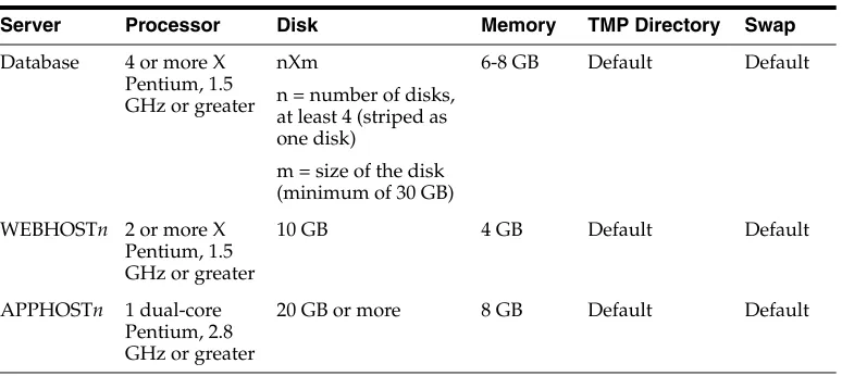
Typical hardware requirements for the Enterprise Deployment on Linux operating systems are listed in Table 1–1.
For detailed requirements, or for requirements for other platforms, see the Oracle Fusion Middleware Installation Guide for that platform.
1.5 Enterprise Deployment Reference Topology
The instructions and diagrams in this document describe a reference topology, to which variations may be applied.
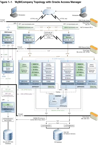
This document provides configuration instructions for a reference enterprise topology that uses Oracle Business Intelligence with Oracle Access Manager, as shown in
Figure 1–1.
Table 1–1 Typical Hardware Requirements
Server Processor Disk Memory TMP Directory Swap
Database 4 or more X Pentium, 1.5 GHz or greater
nXm
n = number of disks, at least 4 (striped as one disk)
m = size of the disk (minimum of 30 GB)
6-8 GB Default Default
WEBHOSTn 2 or more X Pentium, 1.5 GHz or greater
10 GB 4 GB Default Default
APPHOSTn 1 dual-core Pentium, 2.8 GHz or greater
Figure 1–1 MyBICompany Topology with Oracle Access Manager
This section covers the following topics:
■ Section 1.5.1, "Oracle Identity Management" ■ Section 1.5.2, "Web Tier"
Enterprise Deployment Reference Topology
1.5.1 Oracle Identity Management
Integration with the Oracle Identity Management system is an important aspect of the enterprise deployment architecture. This integration provides features such as single sign-on, integration with OPSS, centralized identity and credential store,
authentication for the WebLogic domain, and so on. The IDM (Identity Management) EDG is separate from this EDG and exists in a separate domain by itself. For more information on identity management in an enterprise deployment context, see Oracle Fusion Middleware Enterprise Deployment Guide for Oracle Identity Management.
The primary interface to the IDM EDG is the LDAP traffic to the LDAP servers, the OAP (Oracle Access Protocol) to the OAM Access Servers, and the HTTP redirection of authentication requests.
1.5.2 Web Tier
Nodes in the Web tier are located in the DMZ public zone.
In this tier, two nodes, WEBHOST1 and WEBHOST2, run Oracle HTTP Server configured with WebGate and mod_wl_ohs.
Through mod_wl_ohs, which allows requests to be proxied from Oracle HTTP Server to Oracle WebLogic Server, Oracle HTTP Server forwards the requests to Oracle WebLogic Server running in the application tier.
WebGate (which is an Oracle Access Manager component) in Oracle HTTP Server uses Oracle Access Protocol (OAP) to communicate with Oracle Access Manager running on OAMHOST2, in the Identity Management DMZ. WebGate and Oracle Access Manager are used to perform operations such as user authentication.
The Web tier also includes a load balancer router to handle external requests. External requests are sent to the virtual host names configured on the load balancer. The load balancer then forwards the requests to Oracle HTTP Server.
The WebGate module in Oracle HTTP Server uses Oracle Access Protocol (OAP) to communicate with Oracle Access Manager to perform operations such as querying user groups.
On the firewall protecting the Web tier, only the HTTP ports are open: 443 for HTTPS, and 80 for HTTP.
1.5.2.1 Load Balancer Requirements
This enterprise topology uses an external load balancer. This external load balancer should have the following features:
■ Ability to load-balance traffic to a pool of real servers through a virtual host name Clients access services using the virtual host name (instead of using actual host names). The load balancer can then load balance requests to the servers in the pool.
■ Port translation configuration
This feature is necessary so that incoming requests on the virtual host name and port are directed to a different port on the back-end servers.
■ Monitoring of ports on the servers in the pool to determine the availability of a service
– The load balancer should allow configuration of multiple virtual servers. For each virtual server, the load balancer should allow configuration of traffic management on multiple ports. For example, for Oracle HTTP Server in the Web tier, the load balancer must be configured with a virtual server and ports for HTTP and HTTPS traffic.
– The virtual server names must be associated with IP addresses and be part of your DNS. Clients must be able to access the external load balancer through the virtual server names.
■ Ability to detect node failures and immediately stop routing traffic to the failed node
■ Fault-tolerant mode
It is highly recommended that you configure the load balancer to be in fault-tolerant mode.
■ Ability to configure the virtual server to return immediately to the calling client It is highly recommended that you configure the load balancer virtual server to return immediately to the calling client when the back-end services to which it forwards traffic are unavailable. This is preferred over the client disconnecting on its own after a timeout based on the TCP/IP settings on the client computer.
■ Sticky routing capability
Sticky routing capability is the ability to maintain sticky connections to components. Examples of this include cookie-based persistence, IP-based persistence, and so on.
■ SSL acceleration
The load balancer should be able to terminate SSL requests at the load balancer and forward traffic to the back-end real servers using the equivalent non-SSL protocol (for example, HTTPS to HTTP). Typically, this feature is called SSL acceleration and it is required for this EDG.
1.5.3 Application Tier
Nodes in the application tier are located in the DMZ secure zone.
APPHOST1 and APPHOST2 run the Oracle WebLogic Server Administration Console and Oracle Enterprise Manager Fusion Middleware Control, but in an active-passive configuration. You can fail over the Administration Server manually (see Section 5.14, "Manually Failing Over the Administration Server to APPHOST2"); alternatively you can configure the Administration Console with CFC/CRS to fail over automatically on a separate hardware cluster (not shown in this architecture).
The Oracle Business Intelligence Cluster Controller and Oracle BI Scheduler system components run on APPHOST1 and APPHOST2 in an active-passive configuration. The other Oracle Business Intelligence system components, Oracle BI Server, Oracle BI JavaHost, and Oracle BI Presentation Services, run on APPHOST1 and APPHOST2 in an active-active configuration. All system components are managed by OPMN and do not run in the Managed Servers.
The Oracle Business Intelligence Java components, including Oracle Real-Time Decisions, Oracle BI Publisher, Oracle BI for Microsoft Office, and the Oracle BI Enterprise Edition Analytics application, run in the two Managed Servers on
Enterprise Deployment Reference Topology
in the EDG topology. WSM Policy Manager runs in active-active configuration in the two Managed Servers in APPHOST1 and APPHOST2.
1.5.4 Data Tier
Nodes in the data tier are located in the most secured network zone (the intranet).
In this tier, an Oracle RAC database runs on the nodes CUSTDBHOST1 and
CUSTDBHOST2. The database contains the schemas needed by the Oracle Business Intelligence components. The Oracle Business Intelligence components running in the application tier access this database.
On the firewall protecting the data tier, the database listener port (typically, 1521) is required to be open. The LDAP ports (typically, 389 and 636) are also required to be open for the traffic accessing the LDAP storage in the IDM EDG.
1.5.5 What to Install
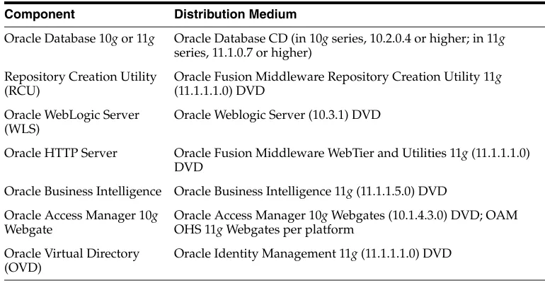
Table 1–2 identifies the source for installation of each software component. For more information, see Oracle Fusion Middleware Installation Guide for Oracle Business Intelligence.
1.5.6 Unicast Requirement
Oracle recommends that the nodes in the MyBICompany topology communicate using unicast. Unlike multicast communication, unicast does not require cross-network configuration and it reduces potential network errors that can occur from multicast address conflicts as well.
The following considerations apply when using unicast to handle cluster communications:
■ All members of a WebLogic cluster must use the same message type. Mixing between multicast and unicast messaging is not allowed.
■ Individual cluster members cannot override the cluster messaging type.
■ The entire cluster must be shut down and restarted to change the message modes (from unicast to multicast or from multicast to unicast).
Table 1–2 Components and Installation Sources
Component Distribution Medium
Oracle Database 10g or 11g Oracle Database CD (in 10g series, 10.2.0.4 or higher; in 11g series, 11.1.0.7 or higher)
Repository Creation Utility (RCU)
Oracle Fusion Middleware Repository Creation Utility 11g (11.1.1.1.0) DVD
Oracle WebLogic Server (WLS)
Oracle Weblogic Server (10.3.1) DVD
Oracle HTTP Server Oracle Fusion Middleware WebTier and Utilities 11g (11.1.1.1.0) DVD
Oracle Business Intelligence Oracle Business Intelligence 11g (11.1.1.5.0) DVD
Oracle Access Manager 10g Webgate
Oracle Access Manager 10g Webgates (10.1.4.3.0) DVD; OAM OHS 11g Webgates per platform
Oracle Virtual Directory (OVD)
■ JMS topics configured for multicasting can access WebLogic clusters configured for unicast because a JMS topic publishes messages on its own multicast address that is independent of the cluster address. However, the following considerations apply:
– The router hardware configurations that allow unicast clusters may not allow JMS multicast subscribers to work.
– JMS multicast subscribers must be in a network hardware configuration that allows multicast accessibility. (That is, JMS subscribers must be in a
2
2
Database and Environment Preconfiguration
This chapter describes database and network environment preconfiguration required by the Oracle Business Intelligence enterprise topology, as well as recommendations for shared storage and directory structure.
This chapter contains the following topics:
■ Section 2.1, "Database Environment Preconfiguration" ■ Section 2.2, "Network Environment Preconfiguration"
■ Section 2.3, "Shared Storage and Recommended Directory Structure" ■ Section 2.4, "Clock Synchronization"
2.1 Database Environment Preconfiguration
You must install a database and then load the Oracle Business Intelligence schemas into it before you can configure the Oracle Fusion Middleware components. You load the Oracle Business Intelligence schemas using the Repository Creation Utility (RCU).
For the enterprise topology, an Oracle Real Application Clusters (Oracle RAC) database is highly recommended to achieve a highly available data tier. When you install Oracle Business Intelligence, the installer prompts you to enter the information for connecting to the database that contains the required schemas.
This section covers the following topics:
■ Section 2.1.1, "Setting Up the Database"
■ Section 2.1.2, "Loading the Oracle Business Intelligence Schemas in the Oracle
RAC Database"
■ Section 2.1.3, "Backing Up the Database"
2.1.1 Setting Up the Database
Before loading the Oracle Business Intelligence schemas into your database, ensure that the database meets the requirements described in the following sections:
■ Section 2.1.1.1, "Database Host Requirements"
Database Environment Preconfiguration
■ Section 2.1.1.3, "Database Services"
2.1.1.1 Database Host Requirements
On the hosts CUSTDBHOST1 and CUSTDBHOST2 in the data tier, note the following requirements:
■ Oracle Clusterware
For 11g Release 1 (11.1) for Linux, refer to Oracle Clusterware Installation Guide for Linux.
■ Oracle Real Application Clusters
For 11g Release 1 (11.1) for Linux, refer to Oracle Real Application Clusters Installation Guide for Linux and UNIX. For 10g Release 2 (10.2) for Linux, refer to
Oracle Database Oracle Clusterware and Oracle Real Application Clusters Installation Guide for Linux.
■ Automatic Storage Management (optional)
ASM is installed for the node as a whole. It is recommended that you install it in a separate Oracle home from the Oracle Database Oracle home. You can select this option when running the runInstaller. In the Select Configuration page, select the Configure Automatic Storage Management option to create a separate Oracle home for ASM.
2.1.1.2 Supported Database Versions
Oracle Business Intelligence requires the presence of a supported database and schemas. To check if your database is certified or to see all certified databases, refer to the "Oracle Fusion Middleware 11g Release 1 (11.1.1.x)" product area on the Oracle Fusion Middleware Supported System Configurations page on the Oracle Technology Network at:
http://www.oracle.com/technology/software/products/ias/files/fusion_ certification.html
To check the release of your database, you can query the PRODUCT_COMPONENT_VERSION view as follows:
Example 2–1
SQL> SELECT VERSION FROM SYS.PRODUCT_COMPONENT_VERSION WHERE PRODUCT LIKE '%Oracle%';
2.1.1.3 Database Services
Oracle recommends using the Oracle Enterprise Manager Cluster Managed Services Page to create database services that client applications can use to connect to the database. For complete instructions on creating database services, see the chapter on workload management in the Oracle Database Oracle Clusterware and Oracle Real Application Clusters Administration and Deployment Guide.
1. Use the CREATE_SERVICE subprogram to create the biedg.mycompany.com database service. Log onto SQL*Plus as the SYSDBA user and run the following command:
SQL> EXECUTE DBMS_SERVICE.CREATE_SERVICE (SERVICE_NAME => 'biedg.mycompany.com', NETWORK_NAME => 'biedg.mycompany.com');
2. Add the service to the database and assign it to the instances using srvctl:
prompt> srvctl add service -d custdb -s biedg -r custdb1,custdb2
3. Start the service using srvctl:
prompt> srvctl start service -d custdb -s biedg
Oracle recommends that a specific database service be used for a product suite even when they share the same database. It is also recommended that the database service used is different than the default database service. In this case, the database is
custdb.mycompany.com and the default service is one with the same name. The Oracle Business Intelligence installer is configured to use the service biedg.mycompany.com.
2.1.2 Loading the Oracle Business Intelligence Schemas in the Oracle RAC Database
Perform these steps to load the Oracle Business Intelligence schemas into your database:
1. Insert the Repository Creation Utility (RCU) DVD, and then start RCU from the bin directory in the RCU home directory.
prompt> cd RCU_HOME/bin prompt> ./rcu
2. In the Welcome screen, click Next.
3. In the Create Repository screen, select Create to load component schemas into a database. Click Next.
4. In the Database Connection Details screen, enter connect information for your database:
■ Database Type: Select Oracle Database.
■ Host Name: Specify the name of the node on which the database resides. For the Oracle RAC database, specify the VIP name or one of the node names as the host name: CUSTDBHOST1-VIP.
■ Port: Specify the listen port number for the database: 1521.
■ Service Name: Specify the service name of the database (biedg.mycompany.com).
■ Username: Specify the name of the user with DBA or SYSDBA privileges: SYS.
■ Password: Enter the password for the SYS user.
■ Role: Select the database user's role from the list: SYSDBA (required by the SYS user).
Click Next.
Database Environment Preconfiguration
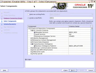
5. In the Select Components screen, do the following:
■ Select Create a new Prefix, and then enter a prefix to use for the database schemas (for example, DEV or PROD). You can specify up to six characters as a prefix. Prefixes are used to create logical groupings of multiple repositories in a database. For more information, see Oracle Fusion Middleware Repository Creation Utility User's Guide.
■ Select the following components:
– AS Common Schemas:Metadata Services (automatically selected)
– Oracle Business Intelligence: Business Intelligence Platform
Click Next.
Figure 2–1 shows the Select Components screen.
Figure 2–1 Repository Creation Utility Select Components Screen
6. In the Schema Passwords screen, enter passwords for the main schema users, and click Next.
You can choose either Use same passwords for all schemas or Specify different passwords for all schemas, depending on your requirements.
Do not select Use main schema passwords for auxiliary schemas. The auxiliary passwords are derived from the passwords of the main schema users.
7. In the Map Tablespaces screen, choose the tablespaces for the selected components, and click Next.
8. In the Summary screen, click Create.
9. In the Completion Summary screen, click Close.
2.1.3 Backing Up the Database
After you have loaded the Oracle Business Intelligence schemas in your database, you should make a backup.
Backing up the database enables you to quickly recover from any issues that may occur in subsequent steps. You can choose to use your database backup strategy for this purpose, or you can simply make a backup using operating system tools or Oracle Recovery Manager (RMAN). It is recommended that you use RMAN for the database, particularly if the database was created using Oracle ASM. If possible, you can also perform a cold backup using operating system tools such as tar.
2.2 Network Environment Preconfiguration
You must ensure that every computer where you plan to run Oracle Business
Intelligence can access (ping) the primary host computer of your cluster using its fully qualified domain name. For the installation to succeed, every computer on which you scale out your installation must be able to support bidirectional communication with the Administration Server on the cluster’s primary host.
This section contains the following topics:
■ Section 2.2.1, "Virtual Server Names" ■ Section 2.2.2, "Load Balancers" ■ Section 2.2.3, "IPs and Virtual IPs" ■ Section 2.2.4, "Firewalls and Ports"
2.2.1 Virtual Server Names
The BI enterprise topology uses the following virtual server names:
■ bi.mycompany.com
■ admin.mycompany.com
Tip: Note the names of the schema passwords, because the upcoming steps require this information.
Note: Oracle recommends using the database used for identity management (see Chapter 9, "Integrating with Oracle Identity Management") to store the Oracle WSM policies. It is therefore expected that you will use the identity management database information for the OWSM MDS schemas, which will be different from the one used for the rest of the BI schemas. To create the required schemas in the identity management database, repeat the preceding steps using the identity management database information, but select only "AS Common Schemas: Metadata Services" in the Select
Network Environment Preconfiguration
■ biinternal.mycompany.com
Ensure that the virtual server names are associated with IP addresses and are part of your DNS. The nodes running Oracle Fusion Middleware must be able to resolve these virtual server names.
2.2.1.1 bi.mycompany.com
bi.mycompany.com is a virtual server name that acts as the access point for all HTTP traffic to the run-time Oracle BI components. Traffic to SSL is configured. Clients access this service using the address bi.mycompany.com:443. This virtual server is defined on the load balancer.
2.2.1.2 admin.mycompany.com
admin.mycompany.com is a virtual server name that acts as the access point for all internal HTTP traffic that is directed to administration services such as Oracle WebLogic Administration Server Console and Oracle Enterprise Manager.
The incoming traffic from clients is not SSL-enabled. Clients access this service using the address admin.mycompany.com:80 and the requests are forwarded to port 7777 on WEBHOST1 and WEBHOST2. This virtual server is defined on the load balancer.
2.2.1.3 biinternal.mycompany.com
biinternal.mycompany.com is a virtual server name used for internal invocation of BI services. This URL is not exposed to the internet and is only accessible from the intranet.
The incoming traffic from clients is not SSL-enabled. Clients access this service using the address biinternal.mycompany.com:80 and the requests are forwarded to port 7777 on WEBHOST1 and WEBHOST2. This virtual server is defined on the load balancer.
2.2.2 Load Balancers
This enterprise topology uses an external load balancer. For more information on load balancers, see Chapter 4, "Configuring the Web Tier."
Configuring the Load Balancer
Perform these steps to configure the load balancer:
1. Create a pool of servers. You will assign this pool to virtual servers.
2. Add the addresses of the Oracle HTTP Server hosts to the pool. For example:
■ WEBHOST1:7777
■ WEBHOST2:7777
3. Configure a virtual server in the load balancer for bi.mycompany.com:443.
■ For this virtual server, use your system's frontend address as the virtual server address (for example, bi.mycompany.com). The frontend address is the
Note: The Oracle Technology Network
(http://www.oracle.com/technology) provides a list of validated load balancers and their configuration at:
externally facing host name used by your system and that will be exposed in the Internet.
■ Configure this virtual server with port 80 and port 443. Any request that goes to port 80 should be redirected to port 443.
■ Specify HTTP as the protocol.
■ Enable address and port translation.
■ Enable reset of connections when services and/or nodes are down.
■ Assign the pool created in step 1 to the virtual server.
■ Create rules to filter out access to /console and /em on this virtual server. 4. Configure a virtual server in the load balancer for admin.mycompany.com:80.
■ For this virtual server, use your internal administration address as the virtual server address (for example, admin.mycompany.com). This address is typically not externalized.
■ Specify HTTP as the protocol.
■ Enable address and port translation.
■ Enable reset of connections when services and/or nodes are down.
■ Optionally, create rules to allow access only to /console and /em on this virtual server.
■ Assign the pool created in step 1 to the virtual server.
5. Configure a virtual server in the load balancer for biinternal.mycompany.com:80.
■ For this virtual server, use your internal administration address as the virtual server address (for example, biinternal.mycompany.com). This address is typically not externalized.
■ Specify HTTP as the protocol.
■ Enable address and port translation.
■ Enable reset of connections when services and/or nodes are down.
■ Assign the pool created in step 1 to the virtual server.
■ Optionally, create rules to filter out access to /console and /em on this virtual server.
6. Configure monitors for the Oracle HTTP Server nodes to detect failures in these nodes.
■ Set up a monitor to regularly ping the "/" URL context.
■ For the ping interval, specify a value that does not overload your system. You can try 5 seconds as a starting point.
■ For the timeout period, specify a value that can account for the longest response time that you can expect from your BI system, that is, specify a value greater than the longest period of time any of your requests to HTTP servers can take.
Network Environment Preconfiguration
2.2.3 IPs and Virtual IPs
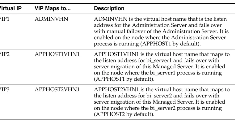
Table 2–1 describes the various virtual hosts.
2.2.3.1 Enabling Virtual IPs for the Managed Servers
The BI domain uses virtual host names as the listen addresses for the Oracle Business Intelligence Managed Servers. You must enable the VIPs, mapping each of these host names on the two BI computers (VIP2 on APPHOST1 and VIP3 on APPHOST2), and they must correctly resolve to the virtual host names in the network system used by the topology (either by DNS Server or hosts resolution).
Before the Managed Servers can be configured to listen on a virtual IP Address, one of the network interface cards on the host running the Managed Server must be
configured to listen on this virtual IP Address.
Perform the following steps once on each host to enable the appropriate virtual IP Address (VIP2 on APPHOST1 and VIP3 on APPHOST2). In an UNIX environment, the command must be run as the root user:
1. On the appropriate host (APPHOST1 or APPHOST2), run the ifconfig command to get the value of the netmask. In a UNIX environment, run this command as the root user. For example, on APPHOST1:
[root@APPHOST1 ~] # /sbin/ifconfig
eth0 Link encap:Ethernet HWaddr 00:11:43:D7:5B:06
inet addr:139.185.140.51 Bcast:139.185.140.255 Mask:255.255.255.0 inet6 addr: fe80::211:43ff:fed7:5b06/64 Scope:Link
UP BROADCAST RUNNING MULTICAST MTU:1500 Metric:1 RX packets:10626133 errors:0 dropped:0 overruns:0 frame:0 TX packets:10951629 errors:0 dropped:0 overruns:0 carrier:0 collisions:0 txqueuelen:1000
RX bytes:4036851474 (3.7 GiB) TX bytes:2770209798 (2.5 GiB) Base address:0xecc0 Memory:dfae0000-dfb00000
2. Bind the virtual IP Address to the network interface card using ifconfig. In a UNIX environment, run this command as the root user. Use a netmask value that was obtained in Step 1.
The syntax and usage for the ifconfig command is as follows:
/sbin/ifconfig networkCardInterface Virtual_IP_Address netmask netMask
Table 2–1 Virtual Hosts
Virtual IP VIP Maps to... Description
VIP1 ADMINVHN ADMINVHN is the virtual host name that is the listen address for the Administration Server and fails over with manual failover of the Administration Server. It is enabled on the node where the Administration Server process is running (APPHOST1 by default).
VIP2 APPHOST1VHN1 APPHOST1VHN1 is the virtual host name that maps to the listen address for bi_server1 and fails over with server migration of this Managed Server. It is enabled on the node where the bi_server1 process is running (APPHOST1 by default).
For example:
/sbin/ifconfig eth0:1 100.200.140.206 netmask 255.255.255.0
3. Update the routing table using arping. In a UNIX environment, run this command as the root user.
/sbin/arping -q -U -c 3 -I networkCardInterface Virtual_IP_Address
For example:
/sbin/arping -q -U -c 3 -I eth0 100.200.140.206
See also Section 5.5.1, "Enabling ADMINVHN on APPHOST1" for information about enabling VIP1 for the Administration Server on APPHOST1.
2.2.4 Firewalls and Ports
Many Oracle Fusion Middleware components and services use ports. As an
administrator, you must know the port numbers used by these services, and ensure that the same port number is not used by two services on a host.
Most port numbers are assigned during installation.
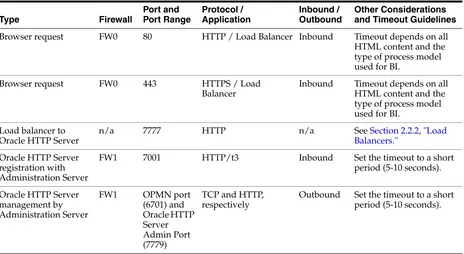
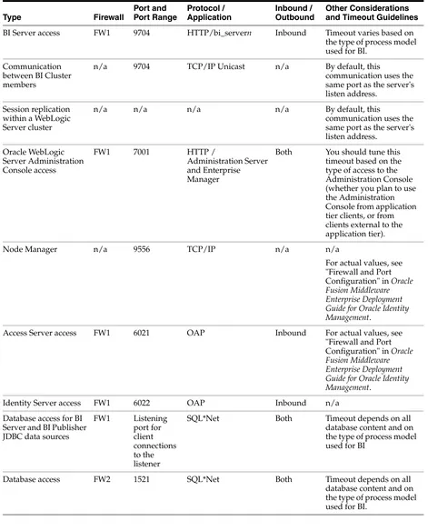
Table 2–2 lists the ports used in the Oracle BI topology, including the ports that you must open on the firewalls in the topology.
Firewall notation:
■ FW0 refers to the outermost firewall.
■ FW1 refers to the firewall between the Web tier and the application tier.
■ FW2 refers to the firewall between the application tier and the data tier.
Table 2–2 Ports Used
Browser request FW0 80 HTTP / Load Balancer Inbound Timeout depends on all HTML content and the type of process model used for BI.
Browser request FW0 443 HTTPS / Load Balancer
Inbound Timeout depends on all HTML content and the type of process model used for BI.
Load balancer to Oracle HTTP Server
n/a 7777 HTTP n/a See Section 2.2.2, "Load
Balancers."
Oracle HTTP Server registration with Administration Server
FW1 7001 HTTP/t3 Inbound Set the timeout to a short period (5-10 seconds).
Network Environment Preconfiguration
BI Server access FW1 9704 HTTP/bi_servern Inbound Timeout varies based on the type of process model used for BI.
Communication between BI Cluster members
n/a 9704 TCP/IP Unicast n/a By default, this
communication uses the same port as the server's listen address. same port as the server's listen address.
Both You should tune this timeout based on the type of access to the Administration Console (whether you plan to use the Administration Console from application tier clients, or from clients external to the application tier).
Node Manager n/a 9556 TCP/IP n/a n/a
For actual values, see "Firewall and Port Configuration" in Oracle Fusion Middleware Enterprise Deployment Guide for Oracle Identity Management.
Access Server access FW1 6021 OAP Inbound For actual values, see "Firewall and Port Configuration" in Oracle Fusion Middleware Enterprise Deployment Guide for Oracle Identity Management.
Identity Server access FW1 6022 OAP Inbound n/a
Database access for BI Server and BI Publisher JDBC data sources
SQL*Net Both Timeout depends on all database content and on the type of process model used for BI
Database access FW2 1521 SQL*Net Both Timeout depends on all database content and on the type of process model used for BI.
Table 2–2 (Cont.) Ports Used
2.3 Shared Storage and Recommended Directory Structure
This section details the directories and directory structure that Oracle recommends for the reference enterprise deployment topology in this guide. Other directory layouts are possible and supported, but the model adopted in this guide was chosen for
maximum availability and provides the best isolation of components and symmetry in the configuration, as well as facilitating backup and disaster recovery. The rest of the document uses this directory structure and directory terminology.
This section contains the following topics:
■ Section 2.3.1, "Terminology for Directories and Directory Environment Variables" ■ Section 2.3.2, "Recommended Locations for the Different Directories"
■ Section 2.3.3, "Shared Storage Configuration"
■ Section 2.3.4, "Ensuring That Shared Network Files Are Accessible in Windows
Environments"
2.3.1 Terminology for Directories and Directory Environment Variables
This enterprise deployment guide uses the following references to directory locations:
■ ORACLE_BASE: This environment variable and related directory path refers to the base directory under which Oracle products are installed.
■ MW_HOME: This environment variable and related directory path refers to the location where Oracle Fusion Middleware resides.
■ WL_HOME: This environment variable and related directory path contains installed files necessary to host an Oracle WebLogic Server.
■ ORACLE_HOME: This environment variable and related directory path refers to the directory where the binaries required to run Oracle Business Intelligence are installed.
■ ORACLE_COMMON_HOME: This environment variable and related directory path refers to the Oracle home that contains the binary and library files required for Oracle Enterprise Manager Fusion Middleware Control and Java Required Files (JRF).
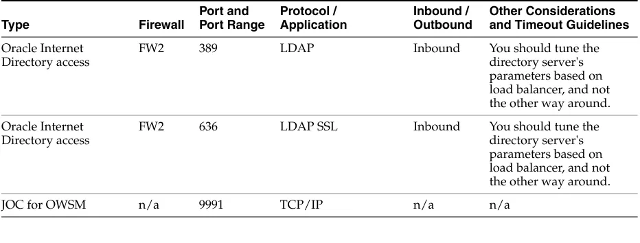
Oracle Internet Directory access
FW2 389 LDAP Inbound You should tune the
directory server's parameters based on load balancer, and not the other way around.
Oracle Internet Directory access
FW2 636 LDAP SSL Inbound You should tune the directory server's parameters based on load balancer, and not the other way around.
JOC for OWSM n/a 9991 TCP/IP n/a n/a
Note: The firewall ports depend on the definition of TCP/IP ports. Table 2–2 (Cont.) Ports Used
Shared Storage and Recommended Directory Structure
■ Domain directory: This directory path refers to the location where the Oracle WebLogic domain information (configuration artifacts) is stored. Different WLS Servers can use different domain directories even when in the same node.
■ ORACLE_INSTANCE: An Oracle instance directory contains configuration files, log files, and temporary files for one or more Oracle system components (such as Oracle BI Server, Oracle BI Presentation Services, Oracle HTTP Server, and so on).
2.3.2 Recommended Locations for the Different Directories
Oracle Business Intelligence 11g supports the deployment and instantiation of multiple processes (such as Managed Servers, BI Servers, and Presentation Services servers) from a single binary installation. This capability simplifies lifecycle operations like patching, upgrade, and test-to-production, as well as scale-out operations for an Oracle Business Intelligence deployment. However, for maximum availability, Oracle recommends using redundant binary installations. In the EDG model, two Oracle Fusion Middleware homes (MW_HOME), each of which has a WL_HOME and an
ORACLE_HOME for each product suite, are installed in a shared storage. Additional servers (when scaling out or up) of the same type can use either one of these two locations without requiring more installations. Ideally, users should use two different volumes (referred to as VOL1 and VOL2 in subsequent text) for redundant binary location, thus isolating as much as possible the failures in each volume. For additional protection, Oracle recommends that these volumes are disk-mirrored. If multiple volumes are not available, Oracle recommends using mount points to simulate the same mount location in a different directory in the shared storage. Although this does not guarantee the protection that multiple volumes provide, it does allow protection from user deletions and individual file corruption.
When an ORACLE_HOME or a WL_HOME is shared by multiple servers on different computers, you should keep the Oracle Inventory (oraInventory) and Middleware home list on those computers up-to-date. Doing so ensures consistency when you perform future installations or apply patches. To update the oraInventory on a computer and "attach" an installation in a shared storage to it, use ORACLE_ HOME/oui/bin/attachHome.sh. To update the Middleware home list to add or remove a WL_HOME, edit the user_home/bea/beahomelist file. This is required for any additional computers where Oracle Business Intelligence is installed, in addition to the two computers used in this EDG.
Oracle recommends also separating the domain directory used by the Administration Server from the domain directory used by the Managed Servers. This allows a symmetric configuration for the domain directories used by Managed Servers, and isolates the failover of the Administration Server. The domain directory for the Administration Server must reside in a shared storage to allow failover to another computer with the same configuration. The domain directories of the Managed Servers can reside in a local or shared storage.
You can use a shared domain directory for all Managed Servers on different computers, or use one domain directory for each computer. Sharing domain
directories for Managed Servers facilitates the scale-out procedures. In this case, the Tip: You can simplify directory navigation by using environment
deployment should conform to the requirements (if any) of the storage system to facilitate multiple computers mounting the same shared volume.
All procedures that apply to multiple local domains apply to a single shared domain. Hence, this enterprise deployment guide uses a model where one domain directory is used for each computer. The directory can be local or reside in shared storage. Based on the preceding assumptions, the following paragraphs describe the directories recommended. Wherever a shared storage location is directly specified, it is implied that shared storage is required for that directory. When using local disk or shared storage is optional, the mount specification is qualified with "if using a shared disk." The shared storage locations are examples and can be changed as long as the provided mount points are used. However, Oracle recommends this structure in the shared storage device for consistency and simplicity.
ORACLE_BASE:
/u01/app/oracle
MW_HOME (Application Tier):
ORACLE_BASE/product/fmw
■ Mount point: ORACLE_BASE/product/fmw
■ Shared storage location: ORACLE_BASE/product/fmw (VOL1 and VOL2) ■ Mounted from: Nodes alternatively mount VOL1 or VOL2 in such a way that at
least half the nodes use an installation and the other half use the other one. In the EDG for Oracle Business Intelligence, APPHOST1 mounts VOL1 and APPHOST2 mounts VOL2. When only one volume is available, nodes mount two different directories in shared storage alternatively (that is, for example, APPHOST1 would use ORACLE_BASE/product/fmw1 as shared storage location and APPHOST2 would use ORACLE_BASE/product/fmw2 as shared storage location).
MW_HOME (Web tier):
ORACLE_BASE/product/fmw/web
■ Mount point: ORACLE_BASE/product/fmw
■ Shared storage location: ORACLE_BASE/product/fmw (VOL1 and VOL2) ■ Mounted from: For shared storage installations, nodes alternatively mount VOL1
or VOL2 in such a way that at least half the nodes use an installation and the other half use the other one. In the EDG for BI, WEBHOST1 would mount VOL1 and WEBHOST2 would mount VOL2. When only one volume is available, nodes mount the two suggested directories in shared storage alternatively (that is, for example, WEBHOST1 would use ORACLE_BASE/product/fmw1 as shared storage location and WEBHOST2 would use ORACLE_BASE/product/fmw2 as shared storage location).
Note: When there is just one volume available in the shared storage, you can provide redundancy using different directories to protect from accidental file deletions and for patching purposes. Two MW_ HOMEs would be available; at least one at ORACLE_
BASE/product/fmw1, and another at ORACLE_
Shared Storage and Recommended Directory Structure
WL_HOME:
MW_HOME/wlserver_10.3 ORACLE_HOME:
MW_HOME/Oracle_BI1 ORACLE_COMMON_HOME:
MW_HOME/oracle_common ORACLE_INSTANCE:
ORACLE_BASE/admin/instance_name
■ If you are using a shared disk, the mount point on the system is ORACLE_BASE/ admin/instance_name mounted to ORACLE_BASE/admin/instance_name (VOL1).
Domain Directory for Admin Directory:
ORACLE_BASE/admin/domain_name/aserver/domain_name (the last "domain_name" is added by the Configuration Assistant).
■ Mount point on system: ORACLE_BASE/admin/domain_name/aserver ■ Shared storage location: ORACLE_BASE/admin/domain_name
■ Mounted from: Only the node where the Administration Server is running needs to mount this directory. When the Administration Server is relocated (failed over) to a different node, the node then mounts the same shared storage location on the same mount point. The remaining nodes in the topology do not need to mount this location.
Domain Directory for Managed Server:
ORACLE_BASE/admin/domain_name/mserver/domain_name
■ If you are using a shared disk, the mount point on the system is ORACLE_
BASE/admin/domain_name/mserver mounted to ORACLE_BASE/admin
/domain_name/Noden/mserver/ (each node uses a different domain directory for Managed Servers).
Location for JMS file-based stores and Tlogs:
ORACLE_BASE/admin/domain_name/cluster_name/jms
ORACLE_BASE/admin/domain_name/cluster_name/tlogs
Note: Web tier installation is usually performed on local storage to the WEBHOST nodes. When using shared storage, appropriate security restrictions for access to the storage device across tiers must be considered.
Note: (VOL1) is optional; you could also use (VOL2).
■ Mount point: ORACLE_BASE/admin/domain_name/cluster_name
■ Shared storage location: ORACLE_BASE/admin/domain_name/cluster_name ■ Mounted from: All nodes running BI components must mount this shared storage
location so that transaction logs and JMS stores are available when server migration to another node takes place.
Location for Oracle BI Presentation Catalog:
ORACLE_BASE/admin/domain_name/cluster_name/catalog/customCatalog (where customCatalog is an example of the catalog name)
■ Mount point: ORACLE_BASE/admin/domain_name/cluster_name
■ Shared storage location: ORACLE_BASE/admin/domain_name/cluster_name ■ Mounted from: All nodes containing the instances of Presentation Services in the
cluster mount this location (all nodes must have read and write access).
Note that the Oracle BI Presentation Catalog is called Presentation Service Repository in Fusion Middleware Control.
Location for Repository Publishing Directory:
ORACLE_BASE/admin/domain_name/cluster_name/ClusterRPD
■ Mount point: ORACLE_BASE/admin/domain_name/cluster_name
■ Shared storage location: ORACLE_BASE/admin/domain_name/cluster_name ■ Mounted from: All nodes containing the instances of BI Server in the cluster
mount this location. The master BI Server must have read and write access to this directory. All other BI Servers must have read access.
Note that the repository publishing directory is identified as the Shared Location for the BI Server Repository in Fusion Middleware Control.
Location for BI Server Global Cache:
ORACLE_BASE/admin/domain_name/cluster_name/GlobalCache
■ Mount point: ORACLE_BASE/admin/domain_name/cluster_name
Shared storage location: ORACLE_BASE/admin/domain_name/cluster_name
Mounted from: All nodes containing the instances of BI Server in the cluster mount this location. The master BI Server must have read and write access to this directory. All other BI Servers must have read access.
Location for BI Publisher Configuration Folder:
ORACLE_BASE/admin/domain_name/cluster_name/bipublisher/config
■ Mount point: ORACLE_BASE/admin/domain_name/cluster_name
■ Shared storage location: ORACLE_BASE/admin/domain_name/cluster_name ■ Mounted from: All nodes containing the instances of BI Publisher in the cluster
mount this location with read/write access.
Location for BI Publisher Scheduler Temp Directory:
ORACLE_BASE/admin/domain_name/cluster_name/bipublisher/temp
■ Mount point: ORACLE_BASE/admin/domain_name/cluster_name