THEORETICAL ANALYSIS OF POSITIONAL UNCERTAINTY IN DIRECT
GEOREFERENCING
Ali Coskun Kiracia, Gonul Tozb
a
Photogrammetry Department, General Command of Mapping, Ankara, Turkey [email protected]
b
ITU, Civil Engineering Faculty, 80626 Maslak Istanbul, Turkey [email protected]
KEY WORDS: GNSS/INS integration, exterior orientation, error propagation, positional uncertainty, direct georeferencing, aero-triangulation
ABSTRACT:
GNSS/INS system composed of Global Navigation Satellite System and Inertial Navigation System together can provide orientation parameters directly by the observations collected during the flight. Thus orientation parameters can be obtained by GNSS/INS integration process without any need for aero triangulation after the flight. In general, positional uncertainty can be estimated with known coordinates of Ground Control Points (GCP) which require field works such as marker construction and GNSS measurement leading additional cost to the project. Here the question arises what should be the theoretical uncertainty of point coordinates depending on the uncertainties of orientation parameters. In this study the contribution of each orientation parameter on positional uncertainty is examined and theoretical positional uncertainty is computed without GCP measurement for direct georeferencing using a graphical user interface developed in MATLAB.
1. INTRODUCTION
The use of GNSS/INS systems in photogrammetry has increased in last decades. GNSS/INS decreased the need for aerial triangulation in photogrammetric applications (stereo applications, orthorectification and the other applications need orientation) partially. Real-time or quasi-real time applications gained importance in almost every earth science. GNSS/INS plays an important role both at frame image orientation and LIDAR (Light Detection and Ranging) applications.
Exterior orientation parameters required for image orientation can be obtained by measurements performed at flight and just after GNSS/INS integration process without the need of aerial triangulation.
When images are oriented directly by GNSS/INS data and get the terrain coordinates it is called “Direct Georeferencing”. Although having the exterior orientation parameters directly seems that there is no need for aero triangulation process and indirectly no need for GCPs (Ground Control Points), in fact there is still need knowledge about positional accuracy of direct
georeferencing and if the results meet that projects’ positional
accuracy need. In addition when GNSS/INS data is used in aerial triangulation as initial values, automatic tie point generation performance improves and also bundle block adjustment converges faster and the results are also impressive. Although GNSS/INS system has advantages because of its speed and cost, GCP(s) is/are needed because position accuracy is mostly determined with experience or empirical tests. On the other hand, GNSS and INS error sources and measurements precision are known in advance. When GNSS/INS data is used directly, accuracy obtained by image orientation is related with GNSS and INS precision. So it is possible to calculate positional uncertainty obtained by direct georefencing performed with GNSS/INS data.
In this study, GNSS and INS error sources are briefed and effect of each orientation parameter is analysed by error propagation of collinearity equations. In addition, positional accuracy is determined in a sample project without any GCP theoretically. coincide exactly. That displacement is related with satellite height and azimuth and varies for L1 and L2 frequency. Choice of proper antenna, using same antenna in relative positioning and orientation of antenna to the north are some precautions to eliminate that displacement.
Atmospheric delay; because ionosphere path is longer at low satellite height angles it raises error. To avoid ionosphere delay double frequency GNSS receivers are used with the knowledge undulation with different frequency are exposed to different resistance.
Delay at troposphere is not related to frequency and can’t be
eliminated with usage of double frequency. Tropospheric effect is modelled in two separate manners (dry and wet). Researches are still going on models developed with temperature and pressure measurements on earth.
Multipath; it occurs with propagation of GNSS signals through two or more paths. This is one the most important error sources.
Multipath error can’t be eliminated by Differential GNSS techniques because it is related to local reflection geometry around the GNSS antenna. The most simple and effective way
to avoid this error is paying attention that there has to be no reflective surfaces around GNSS.
Satellite Geometry; distribution of satellites in space effects positional accuracy. Position accuracy would be worse when observed satellites are close to each other but higher if distribution is homogenous. Geometric error is called as Geometric Dilution of Precision (GDOP). PDOP (Positional Dilution of Precision), VDOP (Vertical Dilution of Precision), TDOP (Time Dilution of Precision) are the parameters that affect positional accuracy. Small values for GDOP states that distribution of satellites in space is good then error caused by satellite geometry is low.
Satellite clock errors and orbit errors, receiver clock error, initial ambiguity errors are reduced with differentiating techniques.
Receiver errors are decreased by technological developments. Satellite distribution comes mostly adequate with the releasement of new satellites. Antenna phase displacement error is removed by using same antennas for observations. Ionospheric delay can be removed with double frequency. Multipath and tropospheric delays are the most important error sources and increases when satellite declination angle decreases. Special antennas and avoiding reflection phases is needed to reduce multipath effect. Tropospheric delay is being studied for modelling with meteorological data and mathematical algorithms.
2.2 INS Error Sources
Initialization errors; Inertial navigators can only integrate received accelerations to propagate initial estimates of position and velocity. Other sources are needed for initial estimates of position and velocity in systems without GNSS. Initialization errors are the errors in these values. (Grewal M. S, 2007).
Alignment errors; an initial period for alignment of gimbals or attitude cosines with respect to navigation axes is included at most standalone INS applications. Errors caused by this process are stated as alignment errors. These errors consist of tilts (rotation about horizontal axes) and heading errors (rotations about the vertical axis).
Sensor adjustment errors; sensor calibration is a procedure for estimating the parameters of models used in error compensation. It is not uncommon for these modelled parameters to change over time and between turn-ons, and designing sensors to make the parameters sufficiently constant can also make the sensors relatively expensive. This problem is being tried to be solved with Kalman Filtering in GNSS/INS applications. The position differences can be used between INS derived position and GNSS derived position to make corrections to calibration parameters.
Gravity Model Errors; it is unknown gravity modelling errors on vehicle dynamics (Grewal M. S, 2007).
3. ERROR PROPAGATION
It is common in engineering applications calculating measured values or the other values by processing those measured values. In this situation error propagation will be the subject according to the mathematical relation while computing the value from that measurement value.
If mean square error and correlation among the measurements are known then the mean square error can be computed by error propagation. Error propagation is mathematically represented in formula (1) (Kutoglu H., 2015)
Error propagation is stated as matrix-vector representation;
= [ … �]
(2)
�
= �+ − �
∗ −− ∗∗ , + − ∗ , − � ∗ ,
, + − ∗ , − � ∗ ,
Linearization of collinearity equations;
= �− � ∗ , + �− � ∗ , − �− � ∗
, (11)
= �− � ∗ , + �− � ∗ , − �− � ∗
, (12)
= �− � ∗ , + �− � ∗ , − �− � ∗
, (13)
�− �=ΔX, �− �= ΔY, �− �= ΔZ (14)
Collinearity equations are linearized for each parameter as shown at formula (15).
�= �
� ∗ [ ∗ (− , ∗ ΔY + , ∗ ΔZ) − ∗
(− , ∗ ΔY + , ∗ ΔZ)] (15)
Design matrix A;
�/ � �/ �/
… … …
…
�/ �/ � �/ �
… … …
… …
… … …
�/ �/ �/
…
… … …
�/ �/ � �/ � (16)
It is assumed that every parameter is uncorrelated. Diagonal
elements of � (Covariance matrix of measurement) are precision of corresponding parameter (1/σ2) and the other parts are zero value.
Finally expected position uncertainty is determined theoretically with formula (6 .
5. IMPLEMENTATION AND ASSESSMENT
Each orientation parameters’ effect on position uncertainty is analysed and expected horizontal and vertical position uncertainty is determined with the help of the mathematical model explained above with MATLAB. An interface is prepared for this application that reads the parameters and enables to edit all parameters of mathematical model (Figure 1). Thus this interface can be used for further photogrammetric projects.
Figure 1. Application interface.
Test parameters are obtained from a project which UltracamX digital camera is used and 6000 m flying height above mean terrain height (f=1005. mm, CCD pixel resolution = 7.2 micron).
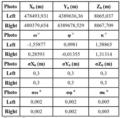
The parameters obtained after GNSS/INS integration and used as input for calculation of position uncertainty are shown at Table 1.
Photo X0 (m) Y0 (m) Z0 (m)
Left 478493,931 4389636,36 8065,037 Right 480379,654 4389678,529 8067,709
Photo ω o φ o κ o
Left -1,55877 0,0981 1,58865 Right 0,28593 -0,01355 1,31314 Photo σX0 (m) σY0 (m) σZ0 (m)
Left 0,3 0,3 0,3
Right 0,3 0,3 0,3
Photo σω o σφ o σκ o
Left 0,002 0,002 0,005 Right 0,002 0,002 0,005 Table 1. Exterior orientation parameters and precisions
PPA (x0, y0) and focal length precision is included in calculation as 1 micron and zero with respectively.
Totally 80 tie points’ image coordinates are measured in each stereo image. Distribution of points is shown at Figure 1.
Figure1. Distribution of tie points in both images
Horizontal position uncertainty is determined as σxy = 0,97 m and vertical position uncertainty is determined as σz = 2,49 m at the end of implementation with the parameters shown above.
Position uncertainty of X, Y and Z components for each point and position uncertainty distribution as colorized surface for whole stereo model generated by interpolation from those points is shown through Figure 2 – Figure 4.
Figure 2.a Position uncertainty of X component of each point
Figure 2.b Distribution of uncertainty for X component for whole stereo model
Figure 3.a Position uncertainty of Y component of each point
Figure 3.b Distribution of uncertainty for Y component for whole stereo model
Figure 4.a Position uncertainty of Z component of each point
Figure 4.b Distribution of uncertainty for Z component for whole stereo model
When the Figures 2 - 4 are examined, it can be seen that X position component is between 0.3 – 0.7 m, Y position component is between 0.4 –1.3 m, Z position component is between 2.0 – 2.7 m.
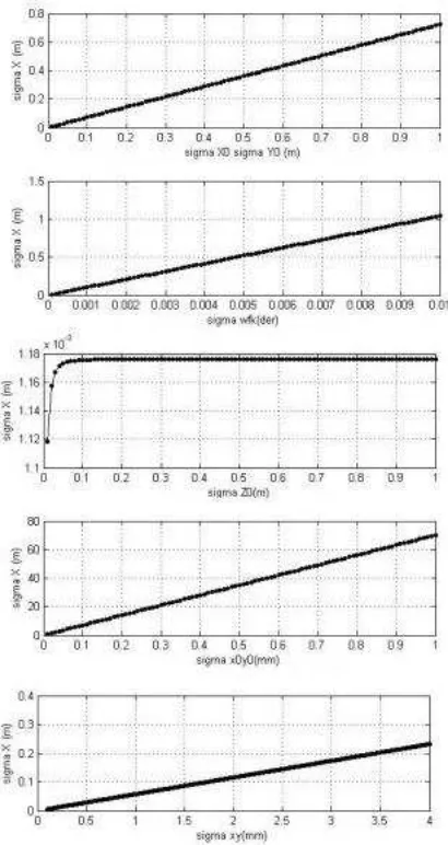
Below effects of each parameter to position uncertainty included in collinearity equations. Here the precision is increased from near zero value by intervals of which
parameters’ effect is analysed and the other parameters’
precision is assumed as constant and without error (near zero value). The effect on X, Y and Z position component of each parameter is represented through Figure 5.a – Figure 5.c.
Figure 5.a Effect of orientation parameters on X component
Figure 5.b Effect of orientation parameters on Y component
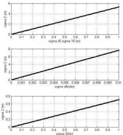
Figure 5.c-1 Effect of orientation parameters to on component Z
Figure 5.c-2 Effect of orientation parameters to on component Z
When the Figures 5a – 5c examined; X and Y position components are affected nearly the same way and their results are said to be close. X0 and Y0 parameter effects on X and Y components at the same ratio nearly 1 to 1 relation and increases the position error linear. Z0 parameter effect on X and Y is very small that can be assumed as approximately zero. Rotation parameters (
,
,
) causes 1.0 -1.5 m position error between 0 o – 0.01o precision. PPA and measurement precision are also quite effective on position uncertainty as shown in the figures.When the orientation parameters’ effect on Z position
component is examined, X0, Y0 X0 precision between 0 – 1 m leads to 5.5 m and rotation angles precision between 0 o– 0.01o leads to 8 m vertical position error. Z0 parameter affects Z component approximately 1 to 1 relation. PPA and measurement precision are also quite effective on position uncertainty as shown in the figures. All parameters’ precision linearly increase Z component error.
In order to detect if the position uncertainty theoretically determined is realistic, the results are compared on 4 GCPs coordinates. The difference between exact coordinates and calculated coordinates are represented in Table 2. The differences are a little bit higher than expected but not unacceptable. Because the GCPs are at the corner of the stereo model the differences can be assumed as meaningful.
ΔX (m) ΔY (m) ΔZ (m)
GCP1 1.30 m 1.21 m 1.82 m
GCP2 1.43m 1.16 m 1.65 m
GCP3 1.17 m 1.33 m 1.94 m
GCP4 1.48 m 1.45 m 1.88 m
Table 2. Differences between known GCPs and calculated coordinates.
6. CONCLUSIONS
Using GNSS/INS data directly in photogrammetric applications is quite economic. Error included in GNSS and INS nature affects position error in results obtained by photogrammetric implementations. Lack of GCPs is still problem in directly use of GNSS/INS applications because of the lack of knowledge
about positional accuracy. However position uncertainty can be computed with the error propagation theoretically. In this study, error propagation is handled with collinearity equations and position uncertainty is examined theoretically. The results are valid for only the orientation and precision parameters used in this study. Although these can be generalized for the other similar projects, a new calculation has to be made to determine the position accuracy. Because, not only parameters but also their uncertainties are included in error propagation determination of position uncertainty has to be performed for every photogrammetric project to get more reliable results theoretically. Besides, the results represent the expected position uncertainty and doesn’t include unknown errors.
In this study, position uncertainty is computed theoretically without GCPs, and examined every orientation parameters effect on position accuracy with the assumption of lack of unknown errors. Stereo application is handled in this study. Orientation of single image can be examined by the same way.
REFERENCES
American Society for Photogrammetry and Remote Sensing, Manual of Photogrammetry Fifth Edition, (2004),
Burman H., “Image Orientation By GNSS And INS”, Department Of Geodesy And Photogrammetry, The Royal Institute Of Technology, Stockholm, Sweden, Commission III, Working Group 1 (2002)
Chiang K., Duong T.T., * Liao J., “The Performance Analysis
of a Real-Time Integrated INS/GNSS Vehicle Navigation
System with Abnormal GNSS Measurement Elimination”, 2011 Ellum C. “Integration Of Raw GNSS Measurements Into A Bundle Adjustment”, Mobile Multi-sensor Systems Research Group, Department of Geomatics Engineering, University of Calgary, Calgary, AB, Canada, 2012
Ellum C., El-Sheimy N., “The Common Adjustment of GNSS
and Photogrammetric Measurements”, From Pharaohs to
Geoinformatics FIG Working Week 2005 and GSDI-8, 2005
Fournier H., Ms.Thesis July 2009, Automated Processing of GNSS/MEMS-IMU Data for Position, Velocity and Attitude Determination
Grewal M. S., Weill L. R., Andrews A. P., 2007, Global Positioning Systems, Inertial Navigation and Integration, 2nd Edition, Wiley
Honkavaara E. “In-Flıght Camera Calıbratıon For Dırect
Georeferencıng”, Finnish Geodetic Institute, Department of
Remote Sensing and Photogrammetry, Finland 2004.
Kim Y. S., Lee, Dong Min Hong, Soon H., Chung C., Sik L., Kang W., Beijing 2008, Coastline Change Analysis Using RTK-GNSS And Aerial Photo, The International Archives of the Photogrammetry, Remote Sensing and Spatial Information Sciences. Vol. XXXVII. Part B8.
Kruck E., “Benefit Of Rigorous Modeling Of GNSS İn Combined AT/GNSS/IMU−Bundle Block Adjustment”, OEEPE Workshop “Integrated Sensor Orientation”, 2001, Kutoğlu H., Görmüş S., Dengeleme Ders Notları,
http://jeodezi.beun.edu.tr/gormus/files/2013/02/dengeleme_hesa b%C4%B1_1_ders_notlar%C4%B1.pdf (08.10.2015)
Lee I.S., Ge L., 2006, The performance of RTK-GNSS for surveying under challenging environmental Conditions, Earth Planets Space, 58, 515–522
Legat K, Skaloud J., Schaer P., “Real-Time Processing Of GNSS/IMU Data For On-The-Fly Quality Control İn Airborne
Mobile Mapping”, 2013
Legat K., Skaloud J. “Reliability of Direct Georeferencing –A
Case Study On Practical Problems And Solutions”, Report to
EuroSDR Commission 1, 2006
Legat K., Skaloud J., Schaer P., Real-time processing of GNSS/IMU data for on-the-fly quality control in airborne mobile mapping ENC-GNSS 2006, Manchester, May 7-10.
Mostafa M. R., Canada (2005), Precise Airborne GNSS Positioning Alternatives for the Aerial Mapping Practice.
P. Schaer , J. Skaloud , P. Tomé , “Towards In-Flıght Qualıty
Assessment Of Aırborne Laser Scannıng” XXI ISPRS
Congress, Beijing, China, July 3-11, 2008.
Passini R., Jewell D., Jacobsen K., “An Accuracy Study On A Large Aırborne GNSS Aero Trıangulatıon Block”, ASPRS
Annual Convention Washington, 2002
Stebler Y., GNSS/IMU Integrity in Airborne Mapping, Ms.Thesis July 2008, Swiss Federal Institute of Technology, Lausanne Geodetic Engineering Laboratory.
Talaya J., International Archives Of Photogrammetry And Remote Sensing. Vol. XXXIII, Part B2. Amsterdam 2000., Robust GNSS Kinematic Positioning For Direct Georeferencing.
Tsai V.J.D., “On GNSS And GNSS-Rtk Assısted
Aerotrıangulatıon” ,ASPRS 2006 Annual Conference, Reno,
Nevada, 2006