POTENTIALS OF IMAGE BASED ACTIVE RANGING TO
CAPTURE DYNAMIC SCENES
S. Hinz a, Ma. Weinmann a, P. Runge b, B. Jutzi a a
Institute of Photogrammety and Remote Sensing, Karlsruhe Institute of Technology (KIT), Englerstr. 7, 76131 Karlsruhe, Germany
b
Geodetic Institute, Karlsruhe Institute of Technology (KIT), Englerstr. 7, 76131 Karlsruhe, Germany
KEY WORDS: Point cloud, range imaging, multi-view, airborne sensing, dynamic observations. ABSTRACT:
Obtaining a 3D description of man-made and natural environments is a basic task in Computer Vision and Remote Sensing. To this end, laser scanning is currently one of the dominating techniques to gather reliable 3D information. The scanning principle inherently needs a certain time interval to acquire the 3D point cloud. On the other hand, new active sensors provide the possibility of capturing range information by images with a single measurement. With this new technique image-based active ranging is possible which allows capturing dynamic scenes, e.g. like walking pedestrians in a yard or moving vehicles. Unfortunately most of these range imaging sensors have strong technical limitations and are not yet sufficient for airborne data acquisition. It can be seen from the recent development of highly specialized (far-)range imaging sensors – so called flash-light lasers – that most of the limitations could be alleviated soon, so that future systems will be equipped with improved image size and potentially expanded operating range. The presented work is a first step towards the development of methods capable for application of range images in outdoor environments. To this end, an experimental setup was set up for investigating these proposed possibilities. With the experimental setup a measurement campaign was carried out and first results will be presented within this paper.
1. INTRODUCTION AND MOTIVATION
Currently the 3D geometrical capturing and description of the environment is based on (multi-view) image or range data. By utilizing passive imaging sensors the 3D information is gained indirectly from several images with stereo- or multiple image analysis. These procedures are widely used but, for certain kinds of applications, they have indispensable limitations due to the constrained camera set-up, the scene contents, and last but not least because of the inherently ill-posed problem of 3D reconstruction from 2D images. For instance the illumination conditions should be adequate, the observed materials need to be textured and opaque, and the distance between object and camera as well as between the camera observation points of stereo images should be sufficiently large enough for gaining a reliable 3D reconstruction.
The photogrammetric methods are complemented by direct measurement procedures like laser scanning. These active sensors capture a sequence of single range values while conducting a time dependent spatial scanning of the environment. In general space-borne, airborne (ALS) as well as terrestrial laser scanners (TLS) provide a direct and illumination-independent measurement of 3D objects (Shan & Toth, 2008; Vosselman & Maas, 2009). For continuous-wave (CW) modulated laser scanning devices the measuring rate is currently between 150000 and 700000 measurements per second and the operating distance is up to 100m. For pulse modulated laser scanning devices the measuring rate is currently between 10000 and 300000 measurements per second and the operating distance is up to 3000m. However, it must be considered that the time-dependent acquisition of the 3D laser points can cause significant artefacts in the point cloud in case the captured scene contains moving objects.
2. STATE OF THE ART AND CHALLENGES
For deriving accurate 3D world coordinates from range measurements, scene as well as the sensor platform must be static or their relative motions must be known precisely.
Otherwise deformation artefacts of the environment will appear and have to be considered before transferring the measured data in a 3D model. In general with an increasing dynamic of the scene contents, respectively sensor platform, the complexity of the analysis increases and the exploitation of three-dimensional information is more and more challenging, especially for laser scanning systems (Toth & Grejner-Brzezinska, 2006; Yao et al., 2010).
Very recently, enhanced types of active imaging sensors are available, namely Swiss Ranger (www.mesa-imaging.ch) and PMD Vision (www.pmdtec.com). These close-range sensors allow to capturing a range image and a co-registered intensity image simultaneously with a high frame rate up to 100 frames per second, so that not just one (or few) points are captured at the same time but a whole frame. The use of both active and passive illumination provides furthermore information of the ambient light, yet allows also to controlling and adjusting the measurement signal – most prominently regarding frame rate, integration time and modulation frequency – to accommodate for the current acquisition conditions in the best manner possible. Another technical advantage is the monostatic sensor configuration, which allows for observing the area of interest from a single point of view, in contrast to the classical stereo observation techniques with passive sensors, which need at least two different observation points. Henceforth, the advantages of active 3D measurement sensors over images and the simultaneous acquisition of areal data have been unified. This concept thus contains much potential for the automatic analysis dynamic scenes in fully 3D. Especially the 3D monitoring with terrestrial or even airborne platforms in challenging weather and illumination conditions is promising with this novel technology.
The major drawbacks are the limited absolute range accuracy of a few centimeters and the limited unambiguous range: Especially the relatively large noise influence on the measurement – which stems from to the large amount of ambient radiation in comparison to the emitted radiation – causes significant inaccuracies of the range measurement. Regarding this aspect, the performance of range imaging (RIM) is usually less reliable than airborne or terrestrial laser scanners. International Archives of the Photogrammetry, Remote Sensing and Spatial Information Sciences, Volume XXXVIII-4/W19, 2011
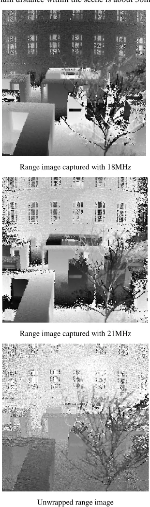
The unique range of the most commercial systems is currently less than 10m and depends on the user-specified modulation frequency. This range measurement restriction can however be significantly relaxed by image- or hardware-based unwrapping procedures, which operate also in far range (Jutzi, 2009; Jutzi, 2011). It could be shown that a range maximum of more than four times of the manufacturers non-ambiguity range specification could be reached without modifying the sensor or improving the illumination unit, e.g. by additional illumination modules. An outdoor example is given by Figure 1: the range images are captured with different modulation frequencies (18 & 21 MHz) and the unwrapped range image is depicted below. The maximum distance within the scene is about 30m.
Range image captured with 18MHz
Range image captured with 21MHz
Unwrapped range image
Figure 1. Range images captured with different modulation frequencies (top: 18MHz; center: 21 MHz) and corresponding unwrapped range image (bottom).
It can be seen from Figure 1 that, although the unwrapped range image is quite noisy concerning the absolute range measurement, the artificial gray value edges of back-folded range measurements have disappeared. With the current technical progress, it can be assumed that the mentioned limitations will be alleviated soon and future systems might be featured by expanded operating range and improved image size.
Beside this the registration procedure is challenging. Usually additional sensor components, e.g. like INS (Inertial Navigation System) and GPS (Global Positioning System), to gain orientation and position of the sensor. Direct measurement of position and attitude of the sensor might still contain systematic errors as it is for instance well-known from strip-adjustment of ALS data. Hence, image-based registration techniques like shown in our previous work (Weinmann et al., 2011; Weinmann & Jutzi, 2011), possibly combined with a bundle approach, should be included to improve accuracy.
In following, some conceptional perspectives regarding the acquisition of dynamic scenes with RIM sensors are described (Section 3). In Section 4, the constructed multi-view range imaging device is introduced, while a “toy scene” for the investigations is shown in Section 5. First results of the measurement campaign and recommendations are given in Section 6. The paper closes with a brief conclusion and outlook.
3. CONCEPTIONAL PERSPECTIVES
While active range scanning devices are more and more established in close-range photogrammetry and computer vision, first – still experimental – developments such as flash-light lasers already show the potential that range imaging devices can be applied to capture larger scenes in the near future. Hence, also the basis for monitoring of highly dynamic scenes can be envisioned. In contrast to the 3D geometry derived by passive sensing techniques (e.g. photogrammetry) the range information is available directly without processing delays. Yet it should be noticed that the range information captured with a single static device is not fully 3D, as only range information corresponding to the well-known bundle of viewing rays can be measured. Still, when using a multi-view camera set-up the observed object or monitored scene can be captured from different directions so that also real 3D descriptions can be derived, even with fewer restrictions than in photogrammetry. In general the multi-view active range imaging can strongly support navigation, (co-)registration, and observing temporal scene changes if a reliable matching procedure is available.
To simulate a future operation of RIM sensors in airborne scene monitoring fairly realistically, a scaled test scenario has been set up. Instead of mounting RIM sensors at unmanned aerial vehicles (UAVs), which involves much efforts and expenses due to the large payload of several kilograms for both the RIM sensors and the data recording system, a sort of cable-car has been constructed (see Figures 3 and 4), on which two RIM sensors and the recording unit have been mounted. This allows (quasi-)airborne monitoring in low altitudes, as they also appear in UAV videos, for capturing dynamic 3D observations like walking pedestrians in a yard or ohter moving objects.
The RIM sensors can be turned into different pointing directions. For the current tests mainly the over-head option was of used, whereby two general constellations were of main International Archives of the Photogrammetry, Remote Sensing and Spatial Information Sciences, Volume XXXVIII-4/W19, 2011
interest: the convergent (a) and the parallel (b) acquisition geometries (see Figure 2):
a) The convergent acquisition geometry (in over-head pointing direction) provides a wider range of viewing directions due to the oblique optical axes, which can be very helpful for 3D object reconstruction and characterization. On the other side, this concept is very challenging for image-based registration due to the different perspectives and the different object appearance in the two images.
b) The parallel acquisition geometry adapts the so-called normal case of photogrammetry and eases many tasks such as co-registration and mosaiking. Especially for image based registration, this constellation is more cooperative due to the similar viewing geometry and similar object appearance in both images. The point density in scenes with steep relief reduces however.
a b
Figure 2. Image acquisition geometry: a) convergent, b) parallel.
4. MULTI-VIEW ACTIVE RANGE IMAGING SYSTEM
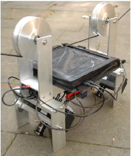
To investigate the potentials of multi-view range imaging systems, an experimental setup based on the above-mentioned cable car concept was developed. The system includes various components of the main sensor rack (Figures 3 and 4):
- two RIM sensors (PMD Vision CamCube 2.0)
- unit for variable multi-view options (viewing possibilities are approximately ± 90° wrt. nadir direction)
- data recording unit for both sensors (notebook with solid state hard disk)
- independent power supply (12V battery with 6.5Ah),
- cable car wheels,
- ropes (100m length).
The measurement staying power is at least 60 minutes and can easily be extended to several hours by utilizing a battery with a larger capacity. For instance, the power consumption of a single PMD Vision CamCube 2.0 is typically between 17W (@2.5ms integration time) and 35W (@10ms integration time). A navigation system to record the absolute position and viewing direction is not on board, as image-based navigation is of our main interest for further investigation. Therefore more focus was put on accurately synchronized image acquisition. To measure the position of the cameras externally, an in-house laser-tracker system could be optionally used.
Figure 3. Visualized CAD model of the experimental device: sensor rack carrying two RIM sensors, capturing unit, and power supply.
The RIM sensors are two PMD Vision CamCube 2.0. The sensors have a 204 x 204 pixel array with a pixel size and pitch (spacing) of about 45 µm. The field of view is 40x40°. The maximum frame rate is about 25 frames per second and the sensor measures three features per pixel: range, active intensity and passive intensity. Therefore, above three million measurement values per second can be captured.
Figure 4. Experimental device ready for measurement.
5. EXPERIMENTS
To obtain first tests and assessments, an outdoor “toy scene” has been set up. It contains bare soil, concrete, a small movable model vehicle and a plant (see Figure 6), where the cable-car with the experimental device could pass by. The scene has been captured with an integration time of 10ms to gain a reasonable signal-to-noise ratio, which is important especially for outdoor measurements. Furthermore various acquisition geometries have been tested. Therefore the rope for the cable-car was mounted at International Archives of the Photogrammetry, Remote Sensing and Spatial Information Sciences, Volume XXXVIII-4/W19, 2011
two points of approximately 3 to 5m height for recording the scene (Figure 5). Please note, that in case of using a convergent viewing geometry as shown in Figure 2a, this height allows already to exceeding the ambiguity range of the PMD sensors.
All tests proved the functionality of the multi-view measurement system.
Figure 5. Experimental device while recording a scene.
Figure 6. Experimental device while recording with scene content.
6. CAPTURED DATA
The captured data can be interpreted in different ways. The measured intensity of active sensors can be generally separated
in an active and passive intensity. The active intensity is often described as amplitude and depends just on the measured scattering received by the active illumination with the sensor, e.g. a laser or diode. The passive intensity measured with an active sensor is often called background illumination, and depends on the illumination given by available extraneous light, e.g. sun light. The passive illumination captured with an active sensor might usually have low spectral information, due to the spectral bandpass filters which are in general used. Further, the range is measured which is for most users of main interest. Sometimes only a phase measurement is utilized to determine the range, where a limited uniqueness range is given by the lowest modulation frequency.
However the captured data for the two acquisition geometries is shown in Section 6.1 (convergent) and Section 6.2 (parallel). For each acquisition geometry, two nearly aligned scene images are depicted. A reliable synchronization of the data is currently an open task which has to be investigated in the future.
6.1 Convergent acquisition geometry
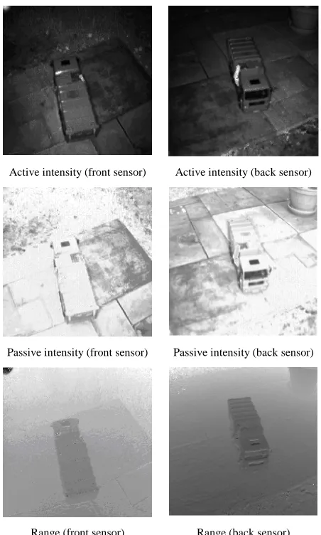
The front sensor is backward looking and the back sensor is forward looking. Obviously with this acquisition geometry more data from the objects side is captured. Active intensity, passive intensity, and phase are depicted in Figure 7. In this case the intensity images look similar except of the different selected dynamic range.
Active intensity (front sensor) Active intensity (back sensor)
Passive intensity (front sensor) Passive intensity (back sensor)
Range (front sensor) Range (back sensor)
Figure 7. Image results of the convergent acquisition geometry. International Archives of the Photogrammetry, Remote Sensing and Spatial Information Sciences, Volume XXXVIII-4/W19, 2011
With the captured images a point cloud can be generated and visualized (Figure 8). Obviously the point cloud is affected by some noise so that – although visible in principle – the vehicle type is hard to recognize in the range data only, due to the low spatial resolution. As can be seen from Figure 7, a combined image and range data analysis seems very promising.
Range (front sensor) Range (back sensor)
Figure 8. Single shot point cloud results of the convergent acquisition geometry.
6.2 Parallel acquisition geometry
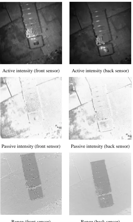
Both sensors are nadir looking with a stereo base of a few decimetres. As expected the images look very similar. Active intensity, passive intensity, and phase are depicted in Figure 9.
Active intensity (front sensor) Active intensity (back sensor)
Passive intensity (front sensor) Passive intensity (back sensor)
Range (front sensor) Range (back sensor)
Figure 9. Image results of the parallel acquisition geometry.
Again the captured images are converted to a point cloud and visualized now in Figure 10. Similar to the convergent case, the
point cloud shows considerable noise and the vehicle type is hard to recognize due to the low image resolution. However, again, as can be seen from Figure 9, a combined image and range data analysis is very promising and, of course, easier as for the convergent case.
Range (front sensor) Range (back sensor)
Figure 10. Single shot point cloud results of the parallel acquisition geometry.
7. CONCLUSION AND OUTLOOK
In this paper the first results for a multi-view range imaging device are presented. The captured data looks very promising. However the data has to be further investigated and it has to be shown that range imaging is superior to range scanning devices, especially for dynamic environments. Therefore a lot of tasks like, e.g., co-registration, have to tackled in the future.
REFERENCES
Jutzi B (2009) Investigations on ambiguity unwrapping of range images. In: Bretar F, Pierrot-Deseilligny M, Vosselman G (Eds.) Laserscanning 2009. International Archives of Photogrammetry and Remote Sensing 38 (Part 3/W8): 265-270. Jutzi B (2011) Extending the range measurement capabilities of modulated range imaging devices by time-frequency-multiplexing. AVN - Allgemeine Vermessungs-Nachrichten. In press.
Shan J, Toth CK (2008) (Eds.) Topographic Laser Ranging and Scanning: Principles and Processing. Boca Raton, FL: Taylor & Francis.
Toth CK, Grejner-Brzezinska D (2006) Extracting dynamic spatial data from airborne imaging sensors to support traffic flow estimation. ISPRS Journal of Photogrammetry & Remote Sensing, 61(3-4): 137-148.
Vosselman G, Maas HG (2009) (Eds.) Airborne and Terrestrial Laser Scanning. Whittles Publishing, Caithness, Scotland, UK. Weinmann Ma, Jutzi B (2011) Fully automatic image-based registration of unorganized TLS data. International Archives of Photogrammetry and Remote Sensing. Submitted.
Weinmann Ma, Weinmann Mi, Hinz S, Jutzi B (2011) Fast and automatic image-based registration of TLS data. ISPRS Journal of Photogrammetry & Remote Sensing. Submitted.
Yao W, Hinz S, Stilla U (2010) Airborne Analysis and Assessment of Urban Traffic Scenes from LiDAR Data - Theory and Experiments. In: Proceedings of Workshop of IEEE Conference on Computer Vision and Pattern Recognition '10 (CVPR'10): 1-8.