TeAM
YYePG
APPLICATIONS SERIES
Consulting Editor
Borko Furht
Florida Atlantic University
Recently Published Titles:
CONTENT-BASED VIDEO RETRIEVAL: A Database Perspective by Milan Petkovic and Willem Jonker; ISBN: 1-4020-7617-7
MASTERING E-BUSINESS INFRASTRUCTURE, edited by Frédéric Patricelli; ISBN: 1-4020-7413-1
SHAPE ANALYSIS AND RETRIEVAL OF MULTIMEDIA OBJECTS by Maytham H. Safar and Cyrus Shahabi; ISBN: 1-4020-7252-X
MULTIMEDIA MINING: A Highway to Intelligent Multimedia Documents edited by Chabane Djeraba; ISBN: 1-4020-7247-3
CONTENT-BASED IMAGE AND VIDEO RETRIEVAL by Oge Marques and Borko Furht; ISBN: 1-4020-7004-7
ELECTRONIC BUSINESS AND EDUCATION: Recent Advances in Internet Infrastructures, edited by Wendy Chin, Frédéric Patricelli, ISBN: 0-7923-7508-4
INFRASTRUCTURE FOR ELECTRONIC BUSINESS ON THE INTERNET by ISBN: 0-7923-7384-7
DELIVERING MPEG-4 BASED AUDIO-VISUAL SERVICES by Hari Kalva; ISBN: 0-7923-7255-7
CODING AND MODULATION FOR DIGITAL TELEVISION by Gordon Drury, Garegin Markarian, Keith Pickavance; ISBN: 0-7923-7969-1
CELLULAR AUTOMATA TRANSFORMS: Theory and Applications in Multimedia Compression, Encryption, and Modeling, by Olu Lafe; ISBN: 0-7923-7857-1
COMPUTED SYNCHRONIZATION FOR MULTIMEDIA APPLICATIONS, by Charles B. Owen and Fillia Makedon; ISBN: 0-7923-8565-9
STILL IMAGE COMPRESSION ON PARALLEL COMPUTER ARCHITECTURES by Savitri Bevinakoppa; ISBN: 0-7923-8322-2
INTERACTIVE VIDEO-ON-DEMAND SYSTEMS: Resource Management and Scheduling Strategies, by T. P. Jimmy To and Babak Hamidzadeh; ISBN: 0-7923-8320-6
ADVANCED WIRED AND
WIRELESS NETWORKS
edited by
Tadeusz A. Wysocki
University of Wollongong, Australia
Arek Dadej
University of South Australia
Beata J. Wysocki
University of Wollongong, Australia
Print ISBN: 387227814
Print ©2005 Springer Science + Business Media, Inc.
All rights reserved
No part of this eBook may be reproduced or transmitted in any form or by any means, electronic, mechanical, recording, or otherwise, without written consent from the Publisher
Created in the United States of America
Boston
©2005 Springer Science + Business Media, Inc.
Visit Springer's eBookstore at: http://www.ebooks.kluweronline.com
PREFACE
PART 1: ADVANCED ISSUES IN AD-HOC
NETWORKING
1.
2.
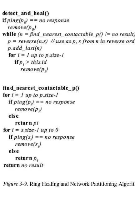
3.
4.
5.
Highly Scalable Routing Strategies: DZTR Routing Protocol
M.Abolhasan and T. Wysocki
Localised Minimum Spanning Tree Flooding in Ad-Hoc Networks
J.Lipman, P.Boustead, and J. Chicharo
A Presence System for Autonomous Networks
A.Dang, and B.Landfeld
Secure Routing Protocols for Mobile Ad-Hoc Wireless Networks
A.A.Pirzada, and C.McDonald
Cross Layer Design for Ad-Hoc Networks
P.Pham, S.Perreau, and A.Jayasuriya
PART 2: IDEAS FOR ADVANCED MOBILITY SUPPORT
6. Federated Service Platform Solutions for Heterogeneous Wireless Networks
H.van Kranenburg, R.van Eijk, M.S.Bargh, and J.Brok
vii
1
19
39
57
81
7.
8.
9.
Reestablishment of Header Compression State by Context Transfer in Mobile IP Networks
H.Duong, A.Dadej, and S.Gordon
Handover Channel Allocation Based on Mobility Predictions
A.Jayasuriya
Mobility Prediction Schemes in Wireless Ad Hoc Networks
PART 3: PERFORMANCE OF ADVANCED NETWORKS
AND PROTOCOLS
10.
11.
12.
13.
An Overview of Streamed Data Authentication Techniques
B. J. Wysocki
Features of Parallel TCP with Emphasis on Congestion Avoidance in Heterogeneous Networks
Q.Fu, and J.Indulska
Performance Analysis of Reliable Multicast Protocols: A Message-Based Approach
J.Tovirac, W.Zhang, and S.Perreau
Fair Queuing in Active and Programmable Networks
We live in the era of information revolution triggered by a widespread availability of Internet and Internet based applications, further enhanced by an introduction of wireless data networks and extension of cellular networks beyond traditional mobile telephony through an addition of the mobile Internet access. The Internet has become so useful in all areas of life that we always want more of it. We want ubiquitous access (anywhere, anytime), more speed, better quality, and affordability. This book aims to bring to the reader a sample of recent research efforts representative of advances in the areas of recognized importance for the future Internet, such as ad hoc networking, mobility support and performance improvements in advanced networks and protocols. In the book, we present a selection of invited contributions, some of which have been based on the papers presented at the 2nd Workshop on the Internet, Telecommunications and Signal Processing held in Coolangatta on the Gold Coast, Australia, in December 2003.
networks, reliable and efficient multicast methods in unreliable networks, and composite scheduling in programmable/active networks where computing resources are of as much importance to network performance as transmission bandwidth.
The editors wish to thank the authors for their dedication and lot of efforts in preparing their contributions, revising and submitting their chapters as well as everyone else who participated in preparation of this book.
Tadeusz A. Wysocki Arek Dadej
HIGHLY SCALABLE ROUTING STRATEGIES:
DZTR ROUTING PROTOCOL
Mehran Abolhasan and Tadeusz Wysocki
Telecommunication and IT Research Institute (TITR) University of Wollongong, NSW 2522, Australia
Abstract
Keywords:
In this paper we present a simulation study of a hybrid routing protocol we pro-posed in our previous work [4] [3]. Our hybrid routing strategy is called Dynamic Zone Topology Routing protocol (DZTR). This protocol has been designed to provide scalable routing in a Mobile Ad hoc Networking (MANET) environment. DZTR breaks the network into a number of zones by using a GPS. The topology of each zone is maintained proactively and the route to the nodes in other zones are determined reactively. DZTR proposes a number of different strategies to reduce routing overhead in large networks and reduce the single point of failure during data forwarding. In this paper, we propose a number of improvements for DZTR and investigate its performance using simulations. We compare the performance of DZTR against AODV, LAR1 and LPAR. Our results show that DZTR has fewer routing overheads than the other simulated routing protocols and achieves higher levels of scalability as the size and the density of the network is increased.
Ad hoc Networks,Routing, DZTR, Scalability.
1.
INTRODUCTION
Similar to most infrustructured or wired networks such as the Internet, MANETs employ a TCP/IP networking model. However, the need to provide end-to-end communication in a dynamic environment, along with the limited resources such as bandwidth and power, demands a redefinition of the layers used in the TCP/IP. Currently, research is being carried out across all layers of the TCP/IP model, to design an infrastructure, which will provide reliable and efficient end-to-end communication for MANETs. One challenging, yet highly researched area in MANETs is routing. In MANET, an intelligent rout-ing strategy is required to provide reliable end-to-end data transfer between mobile nodes while ensuring that each user receives certain level of QoS. Fur-thermore, the routing strategy must minimise the amount of bandwidth, power and storage space used at each end user node. Therefore, traditional routing strategies, such as the link-state and distance vector algorithm, which where intended for wired or infrastructured networks will not work well in dynamic networking environment.
a number of zones by each node. Others group nodes into trees or clusters. Hybrid routing protocols have the potential to provide higher scalability than pure reactive or proactive protocols. This is because they attempt to minimise the number of rebroadcasting nodes by defining a structure (or some sort of a backbone), which allows the nodes to work together in order to organise how routing is to be performed. By working together the best or the most suitable nodes can be used to perform route discovery. For example, in ZHLS only the nodes which lead to the gateway nodes rebroadcast the route discovery packets. Collaboration between nodes can also help in maintaining routing information much longer. For example, in SLURP, the nodes within each region (or zone) work together to maintain location information about the nodes, which are assigned to that region (i.e. their home region). This may potentially eliminate the need for flooding, since the nodes know exactly where to look for a destination every time. Another novelty of hybrid routing protocols is that they attempt to eliminate single point of failure and creating bottleneck nodes in the network. This is achieved by allowing any number of nodes to perform routing or data forwarding if the preferred path becomes unavailable.
Most hybrid routing protocols proposed to date are based. In zone-based routing protocols, the network is divided into a number zones, which can be overlapping ones, such as in ZRP, or non-overlapping such as in ZHLS. The disadvantage of ZRP is that if the zone radius is too large the protocol can behave like a pure proactive protocol, while for a small zone radius it behaves like a reactive protocol. Furthermore, the zones are overlapping, which means that each node can belong to a number of different zones, which increases re-dundancy. The disadvantage of a non-overlapping zone-based protocols such as ZHLS is that the zone partitioning is done at the design stage. This means that all nodes must have preprogrammed zone maps, which are identical for all nodes in the network, or they must obtain a copy of the zone map before routing can occur. Static zone maps can be used in environments where the geo-graphical boundaries of the network are known (or can be approximated). Such environments include: shopping malls, universities or large office buildings, where physical boundaries can be determined and partitioned into a number of zones. However, in environments where the geographical boundaries of the network are dynamic (i.e. can change from time to time as nodes may travel to different regions), a static zone map cannot be implemented. Examples of such networks include: the battlefield where the battle scene may constantly move from one region to another or in search-and-rescue operations in remote areas. In these environments, a dynamic zone topology is required.
perfor-mance using simulation technique. We also compare the perforperfor-mance of DZTR with AODV, LAR1, and LPAR[5], under a number of different network scenar-ios and comment on their scalability in large networks. The rest of this paper is organised as follows. Section II briefly describes the DZTR routing proto-cols. Section III describes the simulation tool and the parameters used in our simulations. Section IV presents a discussion on the results we obtained from the preliminary simulations, and section V presents the concluding remarks for the paper.
2.
DYNAMIC ZONE TOPOLOGY ROUTING
DZTR is a zone based routing protocol is designed to provide scalable routing in large networks with high levels of traffic. The advantage of DZTR over some of the other zone-based routing protocols described in the previous section includes:
Zones are created dynamically rather than using a static zone map such as in ZHLS. This means that a preprogrammed zone map is not required. Each zone only belongs to one zone, which means that information re-dundancy is reduced, while a more collaborative environment is defined. Single-point of failure is reduced, since there is no cluster-head or a root-node. All nodes within each zone work together to determine the best routes with the least amount of overheads, and data forwarding between each zone can still occur without a route failure as long as there is one gateway connecting the two zones.
A number of location tracking strategies is proposed to determine routes with minimum amount of overheads for a number of different scenarios. The DZTR routing protocol is made up of three parts. These are Zone Creation, Topology Determination and Location Discovery. The following sections describe each part.
2.1
Zone Creation
At least one of the nodes are not a gateway node of another zone1.
To create a zone ID, each node records its current location, speed and bat-tery power and exchange it with the other using a Zone-Query packet. The coordinates of the node with the lower speed will be used as the zone centre point, which is used to create and reserve the zone boundary. If the nodes have the same velocity, then the node with the higher battery power will be used as the centre point. The aim here is to select the node which is expected to last the longest in the calculated zone. This means that the calculated zone will be active for a longer time.
When the node which has the higher stability of the two is determined, each node will then calculate the boundary using the centre point and the transmission range of that node. Note that when a node sends a Zone-Query Packet, it also keeps a copy of this packet and waits for the other node to send its Zone-Query Packet. When the neighbours Zone-Query packet is received, it uses the two packet to create the zone. The node will then exchange the calculated zone ID to ensure that they have agreed on the same zone ID. If the zone IDs are different the zone ID of the least mobile node is used based on the mobility information exchanged during the zone ID exchange phase. The zone ID will be a function of the centre point and the zone radius. We have chosen the zone ID to be the concatenation of the zone centre point and the zone radius. 2
Similar to DZTR1, the zones are geographically bounded by a zone radius. However, in DZTR2, the boundary of the zone is chosen in such a way that all nodes are within transmission range [3]. The advantage of this strategy is that there is no partitioning in each zone. Therefore, there is all nodes within each zone are aware of each other. Another advantage is that each node can update its intrazone with just one beacon message, as there is no need for further rebroadcast to reach all different parts of each zone. However, the zones created in DZTR2 are smaller than DZTR1, which means that the number of zones in DZTR2 maybe significantly higher than DZTR1. This can increase the number of interzone migration when mobility is high, which will require each node to become affiliated with different zones more frequently. Hence, processing overhead and intrazone update may be higher than in DZTR1.
1One of the two nodes have a neighbouring node which is a zone member 2
2.2
Topology Determination
In DZTR3, once each nodes determines its zone ID, it will start to build its intrazone and interzone routing tables. The intrazone topology of each dynamic zone is maintained proactively and the topology and/or routes to the nodes in the interzone is determined reactively.
2.2.1 Intrazone routing. The intrazone network topology is maintained proactively. Each node in the network periodically broadcasts its location infor-mation to the other nodes in its intrazone. However, we minimise the number of control packets propagated through the intrazone by setting the frequency at which each node broadcasts its location to be proportional to its mobility and displacement. That is, each node broadcasts its location information through its intrazone if it has travelled (displaced) a minimum distance. This distance is called Minimum Intrazone Displacement (MID). To determine their displace-ment, each node starts by recording its current location at the startup using a GPS device. It will then periodically check its location (if the node is mobile), and compare it with the previously recorded location. If the distance between the current and the previous location is greater than or equal to MID, then the node will broadcast its location information through the intrazone and set its current location as the new previous location.
We call this updating strategy, Minimum Displacement Update (MDU). The advantage of this updating strategy is that updates are sent more frequently if the location of a node has changed significantly. The disadvantage of sending updates based on mobility alone is that if a node travels back and forward in a small region update packets are still disseminated, however, the topology may have not necessarily changed. Therefore, sending an update packet will be wasteful.
Intrazone update packets will also be sent if any of the following conditions occur:
Node travels more than MID within a zone Intrazone-Update Timer (IUT) expires
2.2.2 Interzone topology creation. The nodes that are situated near the boundary of each zone can overhear update or data packets travelling through the nodes in their neighoubouring zones. These nodes may also be in transmission
range of other nodes which are members of another zone. These nodes are referred to as gateway nodes. When a gateway node learns about an existence of another zone, it will broadcast the zone ID of the new zone through its intrazone. This packet is called an Interzone-Update packet (IEZ). This packet includes the gateway nodes node ID, zone ID, location, velocity and learnt zone ID. Therefore, since the gateway includes its velocity and location information, other member nodes can update the information stored in their intrazone table about that gateway node. Hence, the gateways can reset their IUT timer each time they send one of these packets
2.2.3 Interzone migration. When nodes migrate from one zone to another they send a control packet to the previously visited zone, thus leaving behind a trail. The trail information includes the node’s current zone ID, location and velocity. The nodes which receive this trail information update their routing tables. Therefore, the nodes in previously visited zone can forward the location request or data packets for the migrating zone to its current zone.
2.3
Location Discovery
When a node has data to send to a particular destination, if the location of the destination is known, DZTR will attempt a number of different location tracking strategies to determine a fresh route to the destination. The location tracking strategy chosen for a known destination will depend on its physical location, velocity and the time of the last previous communication. If the loca-tion of the destinaloca-tion is not know, DZTR will initiate Limited Zone-hop Search with Multizone Forwarding (LZS-MF) to determine a route while minimising overhead. To initiate different location tracking strategies, DZTR introduces four different routing scenarios:
(i) (ii)
(iii)
(iv)
Destination is in the intrazone or is a temporary member.
Destinations ZID or location is known, and it is expected to be in its current zone.
Destinations ZID or location is known, but its velocity and location in-formation suggest that it could currently lie a number of different neigh-bouring zones.
The location or the ZID of the destination is unknown.
If the destination is not found in the intrazone, then the source will consult its Destination History Table (DHT, described further in [3]. If an entry is found in the DHT, the source will check if the destination still maps in its current zone (using the destinations location, velocity and expiration time in the DHT), if the mapping suggests that the destination is still in its current zone (i.e. case (ii)), the source node will use its interzone table to forward the data packet towards the next zone, which leads to the destination zone.
In (iii), the destination’s velocity indicates that it may not be in its recorded zone. In this case the destination node can lie in any number of zones. To find the current zone ID (or location) of the destination, the source node unicasts a Zone Request packet with destination’s previously recorded location information (i.e. ZREQ-L), to the zone in which the destination was last suspected to be in, using its interzone topology table. When the ZREQ-L packet reaches the destination’s suspected zone, the gateway node which have received this packet will first check to see if the destination is still in the intrazone (or a temporary member). If the destination was not found and no location trail is available, the gateway node will calculate a region in which the destination could have migrated to. We call this the Destinations Expected Region (DER)4, and it is calculated using the destination’s previously known velocity and location information. When the DER is calculated, the gateway node will create a new packet, which includes the source node ID and zone ID, destination ID, a sequence number and the DER. This packet is called a Localised Zone Request (LZREQ). The gateway node forwards this packet to all the neighbouring zones which map into the DER. Each gateway node in the receiving zones will check their tables for the destination, if the destination is not found, they will forward this packet to their outgoing (neighbouring) zones which map into the DER. Note that each node only forward the same LZREQ (or ZREQ) packet once. However, each zone may be queried more than once from different entry points (i.e. gateways). This way if there is clustering within each zone, the zones can still be effectively searched. If the destination is found, the destination will send a ZREP packet back towards the source.
In (iv), the destination’s current zone is not known. In this case to search the network effectively while ensuring that overheads are kept low, we introduce a new zone searching strategy called Limited Zone-hop Search with Multizone Forwarding (LZS-MF). In this strategy the source node generates a ZREQ-N packet (N denotes no location information is available for the destination). This packet includes the source node ID, zone ID, location, sequence number, neigh-bouring zone list and a Zone-Hop (ZH) number. The zone hop number defines the number of zones which the ZREQ-N packet can visit before it expires. To
search for an unknown destination, the source node begins by setting Z H = 1, which means that only the neighbouring zones can be searched. Each time the ZREQ-N discovery produces no results, the source node increments the value of ZH to increase the search area, and the search is initiated again. This search strategy continues until ZH = MAX-COVERAGE-AREA. The advantage of our limited zone-hop search is that if one of the nearby zones has a trail to the destination (or hosts the destination), we avoid searching all the zones in the network. Now, to ensure that not all nodes within each zone are involved in the routing, each time a gateway node in each zone receives a ZREQ-N packet, it uses its interzone topology table to forward the ZREQ-N packet to the nodes, which lead to the neighbouring zones. We call this Multizone For-warding (MF). In this strategy the source node starts by consulting its interzone topology table to determine the list of neighbouring zones. It will then store the list of neighbouring zones, along with the neighbouring nodes which lead to one of these neighbouring zones. These nodes are the only nodes, which can forward the ZREQ-N packet towards the next neighbour leading to a neigh-bouring zone. When a ZREQ-N packet reaches a new zone, the receiving node (i.e. the gateway), will first check its routing tables to see if it has a location information about the destination. If no location destination is found and it has not seen the packet before, it will consult its interzone table and forward the ZREQ-N packet with a new list of neighbouring zones and forwarding nodes. The process continues until the ZH limit is reached, the packet timer expires or the destination is found. When the destination is found, it will send a ZREP packet back towards the source node, indicating its current zone, location and velocity. In DZTR, a link failure may not necessarily lead to route failure. This is because data packets can still be forwarded to their destination if there exists a node which leads towards the destination. A route failure will occur and returned back to the source if no such node can be found.
3.
SIMULATION MODEL
In this section we describe the scenarios and parameters used in our simula-tion. We also describes the performance metrics used to compare our routing strategy with a number of existing routing strategies.
3.1
Simulation Environment and Scenarios
layer, IEEE 802.11 was used in DCF mode. The radio capture effects were also taken into account. Two-ray path loss characteristics was considered as the propagation model. The antenna hight was set to 1.5m, the radio receiver threshold was set to -81 dbm and the receiver sensitivity was set to -91 dbm according to the Lucent wavelan card[2]. Random way-point mobility model was used with the node mobility ranging from 0 to 20m/s and pause time was set to 0 seconds for continuous mobility. The simulation was ran for 200s5 and each simulation was averaged over eight different simulation runs using different seed values.
Constant Bit Rate (CBR) traffic was used to establish communication between nodes. Each CBR packet was contained 64 Bytes and each packet were at 0.25s intervals. The simulation was run for 20 and 50 different client/server pairs6 and each session begin at different times and was set to last for the duration of the simulation.
3.2
Implementation Decisions
The aim of our simulation study was to compare the route discovery per-formance of DZTR under different levels of traffic and node density with a number of different routing protocols. In our simulations, we compare DZTR with LPAR7, AODV and LAR1. We implemented DZTR on the top of AODV using AODV’s existing error recovery strategy, sequence numbering and broad-cast ID strategies. The DZTR2 cluster strategy was implemented as the zone creation strategy in order to eliminate partitioning within each zone and also to allow topology maintenance messages (such as Intrazone, Interzone, Trail updates) to occur by using beaconing messages only. Therefore, each packet is exchanged between neighbouring nodes. For example, when a node sends a trail update packet, this packet is also used by its current intrazone members to update their intrazone table (i.e. it is seen as an intrazone update). Similarly, the nodes in the neighbouring zones update their interzone table and the closest gateway to the node which sent the trail update then broadcasts this trail update in its intrazone.
To reduce the number of intrazone updates in DZTR2, each time a node initiates a ZREQ-N, it also uses this packet to update its intrazone and resets its IUT. Furthermore, to minimise the number of interzone updates propagating through each zone, only the closest known gateway rebroadcasts a learnt zone ID. Similarly, during the zone creation phase, a zone reply is only sent by the node which is closest to the zone which sent a zone query. To minimise the
5 We kept the simulation time lower than the previous chapter due to a very high execution time required for
the 50 Flow scenario
6Note that the terms Client/Server, src/dest and Flows are used interchangeably 7
routing overhead when location information is not available at the source, we modified the LZS-MF strategy so that during the first cycle of route discovery (i.e. first attempt at route discovery), each retransmitting node only select one node to represent each known zone in the interzone table during further rebroadcasts and each packet cannot re-enter the same zone. Furthermore, the chosen nodes must be further away from the source than the current hop. For example, if there are 6 neighbouring zones, then each retransmitting node will choose at most 6 other retransmitting nodes to further rebroadcast the control packets away from the source. If the first cycle fails, then in the second cycle, all nodes in the interzone table are chosen, which are further away from the source than the current hop. Finally, in the third cycle, all nodes in the interzone table are chosen regardless of their position.
Table 1-1 illustrates the simulation parameters used for DZTR.
3.3
Performance Metrics
The performance of each routing protocol is compared using the following performance metrics.
Packet Delivery Ratio (vs) Number of nodes
Normalised control overhead (O/H) (vs) Number of nodes End-to-End Delay (vs) Number of nodes
chosen value of pause time. The last metric is used to investigate the changes in end-to-end delay as the number of nodes is increased. Using these metrics, the level of scalability can be determined by the level of PDR or normalised overhead experienced and the shape of the curves. For example, the protocol which have the highest level of PDR and also maintains the flattest curve, has the highest scalability. For normalised overhead we look for the protocol which has the lowest amount of overhead throughout all different node densities. The last metric is used to investigate the changes in end-to-end delay as the number of nodes is increased.
4.
RESULTS
In this section we present the worst case (i.e. zero pause time and constant mobility) scenario results we obtained from our simulation. The results for other levels of mobility can be seen in Appendix A. To investigate the worst case scenario behaviour of each routing protocol, we recorded the PDR, normalised routing overhead and the end-to-end delay introduced into the network. We recorded this behaviour for up to 500 nodes in the network.
4.1
Packet Delivery Ratio Results
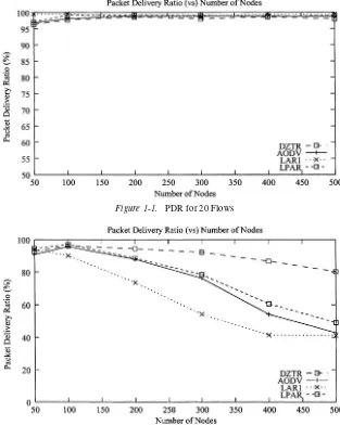
Figure 1-1. PDR for 20 Flows
Figure 1-2. PDR for 50 Flows
always available or valid, especially during high levels of mobility. Therefore, the source nodes may be required to make frequent route recalculations, which will increase the level of bandwidth consumed by routing packets throughout the network.
4.2
Normalised Routing Overhead Results
Fig. 1-3 and 1-4 demonstrate the normalised control overhead for the 20 Flows and the 50 Flows scenarios. In both scenarios DZTR produces the least amount of overhead per packet. Note that as the node density is increased, DZTR maintains the flattest curve when compared to the other three routing strategies, which shows that number of retransmitting nodes do not significantly increase in DZTR. Therefore, the total number of control packets disseminated into the network remains reasonably low as the node density is increased. This shows that DZTR scales significantly better than the other strategies. AODV
Figure 1-3. Normalised overhead for 20 Flows
reduc-Figure 1-4. Normalised overhead for 50 Flows
tion is achieved by using the 3-state route discovery strategy, which attempts to find a route to a required destination by unicasting if location information about the destination is available (described in chapter 4). Thus reducing the need for broadcasting during route discovery. Furthermore, LPAR reduces the number of control packet retransmission by flooding over stable links only.
4.3
Delay Results
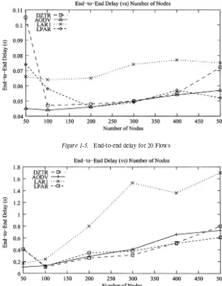
Fig. 1-5 and 1-6 illustrate the end-to-end delay experienced by each data packet for the 20 Flows and the 50 Flows scenarios. In the 20 Flow and 50 Flow scenario for the 50 node network DZTR produces longer delays than the other strategies. Two factor contribute to this extra delay, firstly when the node density is low, the nodes may be engaged in zone creation more frequently as the chance for network partitioning to occur is much higher. This means nodes may go in and out of single-state mode or may become temporary members. Therefore, the information kept in each interzone table may not be very accurate, and the first cycle of route discovery may not always be successful.
Figure 1-5. End-to-end delay for 20 Flows
Figure 1-6. End-to-end delay for 50 Flows
greater than 500. However, LAR1 continues to produce larger delays than the other routing protocols during higher node density levels. This is because when mobility is high, more packets may travel over non-optimal routes with larger hop counts, which may be stored in a route cache (described in Chapter 4). Therefore, these packets will experience longer end-to-end delay than the ones travelling over the shortest path. Furthermore, as the node density is increased, the number of routes stored in the route cache may also increase. This means that more non-optimal routes with large hop counts may be available for each required destination. Hence, the probability of longer (non-optimal) end-to-end delay experienced by each packet also increase.
5.
CONCLUSIONS
This paper presented a new routing protocol for mobile ad hoc networks, which is called Dynamic Zone Topology Routing (DZTR). The idea behind this protocol is to group nodes that are in close proximity of each other into zones. By grouping nodes together and allowing routing and data transmission to be carried out by a group of nodes, we eliminate single points of failure during data transmission, distribute network traffic through a set of nodes and avoid frequent route recalculation. The topology of each routing zone is maintained proactively and each zone member node is aware of the neighbouring zones through the gateway nodes. DZTR reduces routing overheads by reducing the search zone and allowing only selected nodes to forward the control packets. Each node that migrates between zones also leaves transient zone trails, which assist our proposed search strategy to find the destination more quickly and with fewer overheads. Our theoretical overhead analysis and simulation studies showed that DZTR significantly reduces the number of control packets transmitted into the network and achieves higher levels of packet delivery under worst case network conditions when compared to AODV, LAR1 and LPAR.
REFERENCES
Glomosim scalable simulation environment for wireless and wired network systems. In
http://pcl.cs.ucla.edu/projects/glomosim/.
Orinoco pc card. In http://www.lucent.com/orinoco.
M. Abolhasan, T. Wysocki, and E. Dutkiewicz. Zone-Based Routing Algorithm for Mobile Ad Hoc Networks.
M. Abolhasan, T. Wysocki, and E. Dutkiewicz. Scalable Routing Strategy for Dynamic Zone-based MANETs. In Proceedings of IEEE GLOBECOM, Taipei, Taiwan, November 17-21 2002.
Mehran Abolhasan, Tadeusz Wysocki, and Eryk Dutkiewicz. LPAR: An Adaptive Routing Strategy for MANETs. In Journal of Telecommunication and Information Technology,
pages 28–37, 2/2003.
7. 8. 9. 10.
11. 12.
13.
14.
S. Das, C. Perkins, and E. Royer. Ad Hoc On Demand Distance Vector (AODV) Routing. In Internet Draft, draft-ietf-manet-aodv-11.txt, work in progress, 2002.
M. Gerla. Fisheye State Routing Protocol (FSR) for Ad Hoc Networks. In Internet Draft, draft-ietf-manet-aodv-03.txt, work in progress, 2002.
Z.J. Hass and R Pearlman. Zone Routing Protocol for Ad-Hoc Networks. In Internet Draft, draft-ietf-manet-zrp-02.txt, work in progress, 1999.
Mario Joa-Ng and I-T Lu. A Peer-to-Peer Zone-based Two-level Link State Routing for Mobile Ad Hoc Networks. IEEE Journal on Selected Areas in Communications, 17(8), 1999.
D. Johnson, D. Maltz, and J. Jetcheva. The Dynamic Source Routing Protocol for Mobile Ad Hoc Networks. In Internet Draft, draft-ietf-manet-dsr-07.txt, work in progress, 2002. Yong-Bae Ko and Nitin H. Vaidya. Location-Aided Routing (LAR) in Mobile Ad Hoc Networks. In Proceedings of the Fourth Annual ACM/IEEE International Conference on Mobile Computing and Networking (Mobicom ’98), Dallas, TX, 1998.
C.E. Perkins and T.J. Watson. Highly Dynamic Destination Sequenced Distance Vector Routing (DSDV) for Mobile Computers. In ACM SIGCOMM’94 Conference on Commu-nications Architectures, London, UK, 1994.
Seung-Chul Woo and Suresh Singh. Scalable Routing Protocol for Ad Hoc Networks.
LOCALISED MINIMUM SPANNING TREE
FLOODING IN AD-HOC NETWORKS
Justin Lipman1,2, Paul Boustead1, Joe Chicharo1
Telecommunications and IT Research Institute, University of Wollongong, Australia, Cooperative Research Centre for Smart Internet Technology, Australia
Abstract:
Key words:
Information dissemination (flooding) forms an integral part of routing protocols, network management, service discovery and information col-lection. Given the broadcast nature of ad hoc network communications, information dissemination provides a challenging problem. In this chap-ter we compare the performance of existing distributed ad hoc network flooding algorithms indentifying stengths and weaknesses inherent in each mechanism. Additionally we propose to apply the Minimum Span-ning Tree (MST) algorithm in a distributed manner as the basis of an optimised ad hoc network flooding algorithm called Localised Minimum Spanning Tree Flooding (LMSTFlood). LMSTFlood provides signifi-cant reduction in duplicate packet reception, average transmission dis-tance and energy consumed. Thus LMSTFlood limits the broadcast storm problem more effectively than existing optimised flooding
mech-Flooding, Broadcasting, MST, Localised, Distributed, Ad hoc Network, MANET
1.
INTRODUCTION
The advent of portable computers and wireless networking has lead to large growth in mobile computing due to the inherent flexibility of-fered. Most wireless networks are built around an infrastructure, where all communications is routed through base stations that act as gateways between the wireless and wired network. However, there may be situ-ations in which it is impossible or not desirable to construct such an infrastructure.
1 2
An ad hoc network is a collection of wireless mobile nodes forming a temporary network lacking the centralized administration or standard support services regularly available on conventional networks. Nodes in an ad hoc network may act as routers, forwarding packets. Ad hoc networks may undergo frequent changes in their physical topology as mobile nodes may move, thereby changing their network location and link status. New nodes may unexpectedly join the network or existing nodes may unexpectedly leave, move out of range or switch off. Portions of the network may experience partitioning or merging, which is non-deterministic. Ad hoc networks may operate in isolation or connected to a fixed network (Internet) via a base station (gateway). Ad hoc networks are characterised by low bandwidth, high error rates, inter-mittent connectivity (partitioning), limited transmission range, device power constraints and limited processing capabilities. Most importantly, all communications in an ad hoc network is broadcast in nature, there-fore nodes must compete for access to a shared medium.
Information dissemination (flooding) forms an integral part of all com-munications in ad hoc networks. Given the broadcast nature of ad hoc networks, this poses a challenging problem. It is, therefore, important that any information dissemination mechanism in ad hoc networks be optimised to reduce the problems associated with broadcast communi-cations. In [1], the problems associated with information dissemination in ad hoc networks are identified and refered to as the broadcast storm problem. The broadcast storm problem states that flooding is extremely costly and may result in redundant broadcasts, medium contention and packet collisions.
This chapter is organised as follows: Section 2 describes published mechanisms for optimised flooding in ad hoc networks. Section 3 ex-plores the distributed MST and proposes the use of distributed MST as the basis of an optimised flooding mechanism. Section 4 describes the simulation environment and provides results and analysis of the proposed optimised flooding mechanism and existing optimised flood-ing algorithms. Section 5 introduces future work on floodflood-ing reliability. Section 6 concludes the chapter.
2.
OPTIMISED FLOODING MECHANISMS
In [4] flooding mechanisms which attempt to reduce redundant broad-casts are categorized as probabilistic based, area based and neighbour knowledge based. Probabilistic based approaches require an understand-ing of network topology to assign rebroadcast probabilities to nodes. Area based approaches assume nodes have a common transmission range, therefore nodes only rebroadcast if they provide sufficient additional cov-erage. Neighbour knowledge based approaches require that nodes make rebroadcast decisions based upon local neighbourhood knowledge ob-tained via beacon messages.
The simplest mechanism for information dissemination within a net-work is Blind flooding. Blind flooding is used by routing protocols such as AODV [5] and DSR [6] to perform route discovery. Blind flooding may also be used in network management to distribute state information or in zero start auto-configuration. In Blind flooding, a node broadcasts a packet, which is received by its surrounding neighbours. Each receiving neighbour then verifies that it has not broadcast the packet before. If not, then the packet is rebroadcast. Blind flooding terminates when all nodes have received and rebroadcast the packet. Blind flooding always chooses the shortest path, because it chooses every possible path in par-allel. Therefore no other algorithm can produce a shorter delay. Of course this is not quite accurate, as in wireless networks Blind flooding suffers from the broadcast storm problem, which may increase resource contention and hence impede its overall performance.
by efficiently selecting one hop neighbours that provide two hop cover of the network area provided by the complete set of one hop neighbours. These selected one hop neighbours are the multipoint relays for a given node. The mechanism is distributed as each node must determine its own MPR set independent of other nodes. Finding the minimal MPR set is NP-complete, however the following algorithm is proposed:
l
2
3
4
Find all 2-hop neighbours reachable from only one 1-hop neighbour. Assign the 1-hop neighbours as MPRs.
Determine the resultant cover set - the set of 2-hop neighbours that will receive the packet from the current MPR set.
From the remaining 1-hop neighbours not in the MPR set, find the ones that cover the most 2-hop neighbours not in the coverage set.
Repeat from step 2 until all 2-hop neighbours are covered.
MPR attempts to minimize the broadcast storm problem by remov-ing redundant broadcasts and groupremov-ing nodes into sets which may be reached by relay nodes, thereby greatly reducing the number of rebroad-casting nodes. However, it is also possible to limit the broadcast storm problem by reducing transmission power, thus reducing the broadcast effects and allowing for a reduction in power consumption due to trans-mission.
Neighbour Aware Adaptive Power (NAAP) flooding [9] is a distributed two hop neighbour knowledge based flooding mechanism for ad hoc net-works. NAAP employes several mechanisms (neighbour coverage, tran-mission power control, neighbour awareness and local optimisation) to limit the broadcast storm problem and reduce power consumption in both the transmission and reception of packets during an optimised flood. An intuitive description of the NAAP algorithm is:
1
2
3
Upon receiving a broadcast message from a broadcasting node each node (selected by as a relay) determines which of its one-hop neighbours received the same message.
Each relay, then determines its closest set of nodes shared with other neigh-bouring relays and allocates those nodes to its relay set.
Figure 2-1. Formation of RNG using a Lune
A wireless network may be described by the graph G = (V,E), where
V is the set of nodes (vertices) and E the set of edges where
Communication between two nodes is possible if an edge (u,v) belongs
to E. The distance between two nodes u and v is defined as d(u,v).
The Relative Neighbourhood Graph (RNG) [2] shown in Fig. 2-2 is
formed when two nodes are connected with an edge, if their
lune
con-tains no other nodes of the graph. The lune of two nodes u and v,
shown in Fig. 2-1 (in grey) is defined as the intersection of two spheres
of radius d(u,v), one centered at node u and the other at node v. The
use of a localised RNG was first proposed in [10] as a topology
con-trol algorithm to minimize node degrees, hop diameter and maximum
transmission range and ensure connectivity. In [11], RNG is applied to
flooding in ad hoc networks and is used to address the broadcast storm
problem by reducing the transmission range of broadcasting nodes and
ensuring the continuation of a flood. Benefits of RNG compared to MPR
and NAAP are that the RNG may be determined using local one hop
topology information. Nodes in RNG are able to determine whether or
not they need to rebroadcast by constructing the RNG. Therefore there
is no per packet overhead as with MPR and NAAP.
Figure 2-2. Distributed RNG with Local Topology
messages. If a positioning system is not available, distances may be
de-termined through recieved signal strength of beacon messages.
Graphs, such as RNG, in which vertices are connected by an edge, if
the edge satisfies some condition of closeness are called proximity graphs.
In the next section we propose the use of a popular proximity graph,
called the MST, as the basis of a distributed optimised flooding
algo-rithm.
3.
LOCALISED MST FLOODING
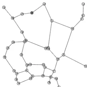
The Minimum Spanning Tree (MST) graph [2], shown in Fig. 2-3, is a
connected graph that uses the minimum total edge length. This results
in a graph with one less edge than the number of vertices. The MST
is traditionally used in networks for determining broadcast trees using
global topology information. The MST is a subgraph of RNG hence the
MST may be computed from the RNG by removing edges that create a
cycle in the graph. This results in the formation of a tree or directed
acyclic graph from all nodes back to the broadcasting node. Thus the
MST generates a more optimal broadcast path than RNG, but suffers
as there is no fault tolerance in the resulting graph [10]. Fault tolerance
refers to the number of alternative paths a message may travel towards
a node, thus improving the probability of delivery.
Figure 2-3. Centralised MST with Global Topology
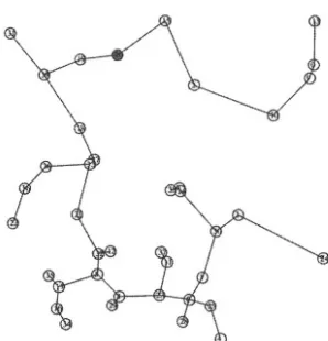
have global topology information for the entire ad hoc network. In this chapter, we propose to apply the MST algorithm in a similar manner to improve the performance of flooding in ad hoc networks. In the dis-tributed MST approach, the topology available to the MST algorithm is restricted to one hop, yet still allows for an optimal broadcast set of nodes with minimal transmission range to be determined as with the centralised approach. Importantly, the resulting distributed MST graph does not exhibit the tree like structure of the centralised MST with global topology knowledge. It can be seen by comparing Figures 2-2, 2-3 and 2-4 that MST Localised MST RNG as described in [3]. Thus many of the benefits of MST are maintained with the addition of fault tolerance not found in the centralised approach.
4.
SIMULATION RESULTS
A simulation was developed that generates a random topology of nodes within a 600 meter by 600 meter area. Nodes have a maximum transmission range of 100 meters. Time is divided into epochs. An ideal MAC layer is assumed. There is no medium contention nor hidden-node scenario within the simulation as it is assumed that during an epoch all nodes can complete their transmission. The transmission medium is error free. A bidirectional link between two nodes is assumed upon reception of a beacon message.
A first order radio model [13] is assumed. In this model the first order radio dissipates to run the circuitry of a transmitter
or receiver and a further for the transmitter amplifier. Equation (2.1) is used to calculate the costs of transmitting
a message a distance Equation (2.2) is used to calculate the costs of receiving a message. The radios have power control and consume the minimal required energy to reach the intended recipients.
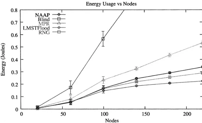
Figure 2-5. A comparison of energy consumed by NAAP, MPR, LMSTFlood, RNG and Blind flooding.
A random node in the topology is selected as the initial node of a flood. Bach random topology is used to determine the performance. The topologies generated are not fully connected therefore some topolo-gies may result in a partitioned ad hoc network. The simulation is run 100 times with a different seed for each number of nodes. The results are averaged and 95% confidence intervals are generated. The figures show the performance of each flooding mechanism as the concentration of nodes is increased.
Figure. 2-6. A comparison of packets transmitted by NAAP, MPR, LMSTFlood, RNG and Blind flooding.
which are not useful). Only the nearest necessary neighbouring nodes that are required to hear a broadcast will hear it. Thus allowing for a reduction in energy consumption and more effective spatial reuse of the broadcast spectrum.
Figure 2-7. A comparison of packets recieved by NAAP, MPR, LMSTFlood, RNG and Blind flooding.
Figure 2-9. A comparison of the per packet overhead for NAAP, MPR, LMSTFlood, RNG and Blind flooding.
quickly as the other mechanisms. This is also evident by the resulting network radius of each mechanism as shown in Fig. 2-10.
Figure 2-9 shows average overhead per broadcast packet in bytes in-curred by NAAP and MPR as the relay set is attached to each broadcast packet. In MPR the multipoint relay set may be distributed through beacon messages and therefore incurs overhead in beacon messages. In the simulation, we append the multipoint relay set to each packet prior to broadcast as done with source based MPR mechanisms [15]. RNG and LMSTFlood incure no additional overhead as each mechanism can determine independently whether or not to rebroadcast. It can be seen that as the node concentration increases, the required overhead of NAAP does not grow significantly. The calculation of overhead does not include neighbor discovery through beacon messages.
Figure 2-10. A comparison of the resulting network radius in hops for NAAP, MPR, LMSTFlood, RNG and Blind flooding.
introduce additional hops and therefore has the lowest network radius. MPR and NAAP may be the most useful to routing protocols as the network radius does not increase dramatically with an increase in node density. Allthough the network radius is higher than MPR, RNG and NAAP do have the added benefits of reducing the the broadcast storm problem more significantly than MPR, thereby providing improved per-formance.
Figure 2-12 shows the node coverage per broadcast with increasing density. As above we see that MPR does not reduce transmission dis-tance and therefore as the node density increases more nodes are covered per broadcast, however as shown in Fig. 2-8 this results in significant duplicate packet reception. NAAP, RNG and LMSTFlood are able to restrict broadcast coverage as node density increases. Therefore they tend to be more scalable in higher node densities.
Figure 2-11. A comparison of the resulting average transmission distance for NAAP, MPR, LMSTFlood, RNG and Blind flooding
more energy per broadcast than the other mechansisms. LMSTFlood provides the lowest overhead, lowest energy consumption, but highest network radius and may not be suitable to route discovery, but may be suited to disseminating link state information or network management information. The NAAP and RNG mechanisms show performance that ranges between LMSTFlood (lower bound) and MPR (upper bound). They may therefore be equally suitable to routing protocols or as general information dissemination mechanisms.
5.
FLOODING RELIABILITY
In IEEE 802.11 [14], the basic medium access mechanism implemented at the MAC layer is Carrier Sense Multiple Access / Collision Avoidance (CSMA/CA). A node utilising CSMA with a data frame to transmit will first sense the shared medium by listening for any existing transmissions. If the medium is busy, then the station will delay its transmission. How-ever, if the medium is not busy, then the node will begin transmitting the data frame. CSMA mechanisms are useful in scenarios where the shared medium is lightly loaded (low traffic) as there is minimal delay prior to transmission. The problem with CSMA is that if the shared medium is heavily loaded (high traffic), then the probability of nodes simultaneously sensing the medium as being free and then transmitting increases. Thus the possibility of obtaining collisions increases.
prior to transmission. The received data frame’s CRC is verified upon re-ception at each receiver and allowed to progress up the protocol stack. If the data frame fails CRC verification, it is deleted. Unlike unicast trans-mission, no positive acknowledgement is transmitted back to the source. The broadcasting node has no mechanism to determine if a broadcast was received by one or all nodes. Given the lack of acknowledgements in broadcast transmission, no data frame retranmissions occur.
The use of the distributed MST algorithm in LMSTFlood allows for a highly optimised flood with the addition of some fault tolerance to improve reliability. However, there still exists a problem in broadcast environments where a broadcast packet may be lost due to noise cor-ruption, packet collisions or hidden node transmissions. In LMSTFlood the number of neighbours that a broadcasting node may need to re-broadcast to is less than 1.5 neighbours on average, once the preceeding broadcasting node is removed from the BSET. There are therefore many situations where a packet may be lost and a flood may not propagate due to low fault tolerance. However, the size of the BSET (1.5 neigh-bours on average) allows for broadcast packet transmissions as used by all flooding mechanisms to be replaced by more reliable unicast packet transmissions such as that used in IEEE 802.11. Unicast transmissions are not completely reliable and packet loss is still possible as each packet will only be retransmitted at most a certain number of times. However, unicast provides a more reliable transport mechanism than broadcast-ing and requires no modifications to the MAC layer. The use of unicast transmission (as opposed to broadcast transmission) combined with LM-STFlood allows for a high degree of optimisation (given the broadcast storm problem) and increased reliability through an acceptable increase in redundancy and the addition of more reliable packet transmission.
6.
CONCLUSIONS
as a general information dissemination mechanism useful in high node concentrations. However due to the resulting high network radius it is not particularly suited to routing protocols. LMSTFlood significantly re-duces energy consumption, utilises a smaller average transmission range and results in nodes receiving less duplicate packets during a flood. It is thus more effective at limiting the broadcast storm problem than existing optimised flooding mechanisms. In addition to the benefits of flooding optimisation, LMSTFlood combined with unicast packet transmission may be used to improve the overall reliability of a flood.
REFERENCES
Problem in a Mobile Ad hoc Networks”. In Proceedings of the Fifth Annual ACM/IEEE International Conference on Mobile Computing and Network-ing, pages 151–162. ACM Press, 1999.G. Toussaint, “The Relative Neighbourhood Graph of Finite Planar Set”.
Pattern Recognition, pages vol. 12, no. 4, pp. 261–268, 1980.
N. Li, J. C. Hou, and L. Sha, “Design and Analysis of an MST-based Topology Control Algorithm”. In Proceedings of IEEE Infocom 2003, 2003. B. Williams and T. Camp. “Comparison of broadcasting techniques for mobile ad hoc networks”. In Proceedings of MOBIHOC, June 9-11 2002. C.E. Perkins and E.M. Royer, “Ad Hoc On-Demand Distance Vector (AODV) Routing”. In Proceedings of the Second Annual IEEE Workshop on Mobile Computing Systems and Applications, pages 90–100, Febuary 1999. D.B. Johnson, D.A. Maltz, and J. Broch, “DSR: The Dynamic Source Rout-ing Protocol for Multihop Wireless Ad Hoc Networks”, in Ad Hoc Network-ing, chapter 5, pages 139–172. Addison Wesley, 2001.
A. Qayyum, L. Viennot, and A. Laouiti, “Multipoint Relaying: An Efficient Technique for Flooding in Mobile Wireless Networks”. In Proceedings of 35th Annual Hawaii International Conference on System Sciences, 2001.
P. Jacquet, P. Muhlethaler, A. Qayyum, A. Laouitim, and L. Viennot, “Op-timized link state routing”, draft-ietf-manet-olsr-06.txt, 2000.
J. Lipman, P. Boustead, and J. Judge, “Neighbor Aware Adaptive Power Flooding in Mobile Ad hoc Networks”. International Journal of Foundations of Computer Science Vol. 14, No. 2, 14(2):237–252, April 2003.
S.A. Borbash and E.H. Jennings, “Distributed Topology Control Algorithm for Multihop Wireless Networks”. In Proceedings 2002 World Congress on Computational Intelligence (WCCI 2002), Honolulu, Hawaii, 2002.
J. Cartigny, F. Ingelrest, and D. Simplot, “RNG Relay Subset Flooding Pro-tocols in Mobile Ad hoc Networks.” In International Journal of Foundations of Computer Science Vol. 14, No, 2, pages 253–265, April 2003.
13.
14.
15.
W.R. Heinzelman, A. Chandrakasan, and H. Balakrishnan, “Energy-efficient Communication Protocol for Wireless Microsensor Networks”. In Proceed-ings of the Hawaii International Conference on System Sciences, pages 1–10, January 2000.
IEEE, “IEEE Std. 802.11-1997 Wireless LAN Medium Access Control (MAC) and Physical Layer (PHY) Specification”.
http://standards.ieee.org/getieee802/, 1997.
A PRESENCE SYSTEM FOR AUTONOMOUS
NETWORKS
Anthony Dang and Bjorn Landfeld
Advanced Networking Research Group, School of Information Technologies, The University of Sydney, Australia
Abstract:
Key words:
This chapter addresses the increasingly important issue of effective addressing, object location and presence notification in networks with no infrastructure and dynamically changing environments. This chapter presents Calto, an architecture comprising presence concepts from Second and Third Generation Mobile networks, Instant Messaging Systems subscriber services, and distributed DNS style functionality in a Peer-to-Peer setting. Calto utilizes locality and key nodes to provide these services. The architecture accommodates for true Ad Hoc environments while being scalable and robust in the face of network instability.
Ad Hoc, Peer to Peer, Resource and Service discovery, Presence, Location, Searching, Distributed Networks
1.
INTRODUCTION
networks may gain and loose connectivity, that is, networks can merge and partition.
In a centralized network, nodes advertise their availability and current location to the centralized server. Services such as object location, DNS and Instant Messaging (IM) [7] are easily provided as centralized servers are generally consistently available and do not change in location. However, with dynamically changing networks, this task becomes much more challenging.
Recently there has been much research in regard to efficient network layer routing to nodes in the wireless domain. Research into effective addressing, presence notification [7] and location in these networks has so far been lagging behind.
Figure 3-1. Converging networking technologies
section 7 we provide an analysis of the scalability of the system before presenting future work in section 8 and finally concluding in section 9.
2.
BACKGROUND
Advances in link layer technologies such as IEEE 802.11 [2] and Bluetooth [10], have allowed for the wireless scene to be extended out of the domain of centralized systems and into the realm of Ad Hoc networks. These networks are envisioned to operate in unstable network environments and without the need for centralized servers. Tracking objects in such a system is inherently difficult. The advent of the Peer-to-Peer paradigm (application layer overlay networks [8,9], communicating via direct links between nodes) has made these hopes attainable. In this section we discuss the applicability of these technologies to this area of research.
2.1
Wireless Location Tracking in GSM
There are many challenges and issues that effect the development of mobile computing [5]. Of particular interest for this research are the problems associated with object location.
GSM cellular networks implement a two-tier scheme where a home database, termed Home Location Register (HLR), is associated with each mobile user. The HLR maintains the current location of the user, that is, a zone in the cellular network where they are currently located. GSM calls this a Visiting Location Register (VLR). To locate a user, their HLR is identified and queried. When a user moves to a new zone, their HLR is contacted and the new location is stored. In GSM systems this method has shown much promise in the way of presence and location of mobile objects.
2.2 Peer-to-Peer
Networks
Peer-to-peer networks appeared on the scene a few years ago in the form of file sharing networks. Rather than downloading files from a centralized server, nodes in the network downloaded them from their peers (hence the name!). The centralized server was used only to index which nodes in the network had what files. Later models of the paradigm completely eliminated the need for a centralized server [11].
proposed for the efficient storage and searching of objects in large scale distributed P2P systems. Unfortunately these proposals do not allow for parts to merge, separate and re-attach, as would be the case in an Ad Hoc environment.
This notion of location, notification and presence in an Ad Hoc network is currently an unexplored area. In our work, we use concepts of the above technologies to achieve this functionality and provide a system for locating users, nodes and services in highly dynamic wired and wireless environments.
3.
CALTO
Calto models some of its aspects on Chord as its simplistic design enables various enhancements that enable Calto’s functionality. In this section we present Calto’s information storage structure, efficiency enhancements and the protocols that enable adaptive addressing.
3.1
Basic Structure
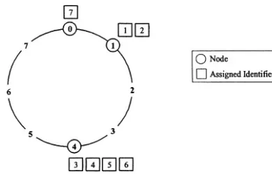
Calto operates as a P2P application-layer overlay network organized in a ring structure, where each node is ordered in terms of an identifier. The architecture provides a distributed lookup service, allowing the insertion, updating, lookup, and deletion of key-value pairs using identifiers as handles to the keys. Examples of searchable identifiers are email addresses, IP addresses, a string name of a service, or even a file name. The node identifiers utilize locality (see section 3.3) and are generated by applying an Ordered Hashing function to the searchable identifier (the identifier known to the person or process conducting a search).
Nodes in Calto are responsible for identifiers that are numerically close to the node’s own identifier. For example, in Fig. 3-2 we can see that the identifiers 1 and 2 are numerically closer to 1 than to 4, so their assignments are to node 1. Node 0 is a special case. The example in Fig. 3-2 depicts a small namespace from 0 to 7. Node 0 is the keeper of identifier 7 because it is mathematically closest to it (closer than node 4!) when the namespace is wrapped around in a ring (or circular list).
keys is implicitly distributed between its immediate successor and predecessor.
It should be noted that this system can store presence information (identifiers) about anything with a unique identifier. This unique identifier can be hashed into a Calto identifier and stored in the system with a mapping to the address or identifier of the node on which this service, resource etc resides.
Figure 3-2. Calto identifier ring with a namespace of 0-7
3.2 A
Multi-tier
Architecture
In any network (large or small) nodes may differ in resource availability (storage capacity, processing power, bandwidth, online availability etc). Calto endeavors to utilize these differences in a hierarchical P2P design, providing scope and flexibility for hybrid [8] client/server functionality (when available) to improve network performance. Specifically, nodes can be elected to be Super Peers, providing a similar function to a server. These nodes hold copies of key-value pairs of their children and adjacent Super Peers allowing for faster searching.
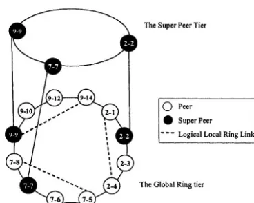
Super Peers maintain their own logical ring overlaying the Global Ring (see Fig. 3-3), enabling the possibility of information backup, and increased performance for information retrieval. The advantage of this design is that it also leaves the network open for the utilization of nodes that may indeed be high-powered centralized servers (permanent or otherwise).
3.3 Exploiting
Locality
resolved locally since it both introduces overhead traffic and drains battery resources. Utilizing the physical layer efficiently is particularly important in this context.
In Chord, all the nodes in the network are organized in a global one-tier ring, and are inherently randomly distributed. In Calto we wish to make use of locality, so rather than randomly distributing identifiers, we use a node’s IP address and spread it evenly over a 160bit address space. For added uniqueness assurance we also add a random value.
Calto endeavors to utilize physical locality to increase network performance, and reduce the cost of sending messages across the physical and data link layers. Thus, Calto allows multiple logical (locality based) rings to overlay its Global Ring structure. The aim is to allow nodes to function independently in Local Rings in addition to operating in a Global Ring context. In other words, we wish to allow nodes to gain access to information about the presence of physically close nodes by using the physical layer as little as possible. In Fig. 3-3 we show a possible network formed by 3 smaller networks (note the dotted lines), all of which consisting of Super Peers which communicate on their own tier.
Figure 3-3. Local and Global Ring overlays and the Super Peer Tier
4.
PRESENCE PROTOCOLS
location). In this section we describe how this can be achieved using concepts from GSM systems and Subscriber Services.
4.1 GSM Style Presence Keepers
In a network where objects can change location, it is important to be able to find them again efficiently. Obviously, if an object never changes location then a search using the original identifier may be performed. However, since we are dealing with the situation where objects can change location then we must have a way of finding them without having to flood the network.
In GSM cellular networks a node will be assigned to Home Location Register (HLR), which will store the current location in the network of that node. The notion of a HLR in Calto is a construct assigned to any node on the network. In effect, in Calto, a HLR may join and leave the network at any time. The nodes a HLR serves are then implicitly assigned to one of a set of possible relative backup nodes to the HLR, as a search would result in one of these nodes, as follows.
When the node enters the system it inserts an identifier in the form “nodeID-fn(‘HLR’)” where nodeID is the node’s identifier, fn() is a hash function, “HLR” is a string and the value of the pair is the node’s current IP address. This allows a node to change location, as its HLR will always be a node close to the identifier “nodeID” which holds a mapping to its current address. A search for a node is simply a search for its HLR.
4.2 Subscribing
to Presence
To be notified of the availability and presence of other nodes and objects in the system, a node must subscribe to the information. Thus each node in the network is aware of the nodes that have subscribed to its presence.