UNIVERSITI TEKNIKAL MALAYSIA MELAKA
DESIGN AND DEVELOPMENT OF CAMERA GUIDED TURRET
SYSTEM
This report submitted in accordance with requirement of the Universiti Teknikal Malaysia Melaka (UTeM) for the Bachelor Degree of Manufacturing Engineering
(Robotics & Automation) (Hons.)
by
MUHAMMAD WINAL ZIKRIL BIN ZULKIFLI B051110264
880927436191
ii
ABSTRACT
iii
ABSTRAK
iv
DEDICATION
v
ACKNOWLEDGEMENT
Bismillahirrahmanirrahim,
Alhamdulillah, thanks to Allah SWT, who with his willing giving me the opportunity to complete this Final Year Project (FYP).
Firstly, I would like to express my deepest gratitude to my project supervisor, En Mahasan bin Mat Ali who had guided me to complete this project successfully. I would like to express an appreciation for his ideas, guidance, encouragement and professionally giving constant support in ensuring this project possible and run smoothly as per planning schedule.
I also truly grateful to those lecturers and staff of the Manufacturing Engineering Department, UTeM that willing to help me in many ways. Sincerely thanks to them for their excellent corporation, supports and inspiration during this project.
Also, thanks to all my friends, those who have been contributed by supporting my work, giving ideas and help me during this project started till it is fully completed.
vi
TABLE OF CONTENT
Abstract ii
Abstrak iii
Dedication iv
Acknowledgement v
Table of Content vi
List of Tables ix
List of Figures x
List Abbreviations xiii
1. INTRODUCTION 1
1.1 Background 1
1.2 Problem statement 3
1.3 Objective 3
1.4 Scope 3
2. LITERATURE REVIEW 4
2.1 Overview 4
2.2 The study and research of microcontroller 4
2.3 The study of DC electric motor 7
2.3.1 Servo motor 10
2.3.2 Stepper Motor 11
2.3.3 Comparison between stepper and servo 17
vii
2.5 Research study on Camera 21
3. METHODOLOGY 26
3.1 Overview 26
3.2 Project scheduling 27
3.3 Project planning 30
3.4 Mechanical 30
3.4.1 Design CAD 31
3.4.2 Modelling of Pan-Tilt System 33
3.5 Electrical 36
3.5.1 Electrical actuator 37
3.5.2 Main controller 39
3.5.3 Programing 40
3.6 Vision analysis 43
3.6.1 Vision system 43
3.6.2 Acquisition image 45
4. RESULT 48
4.2 Electronic Development 56
4.3
5. ANALYSIS AND DISCUSSION 64
viii
6. CONCLUSIONS AND RECOMENDATIONS 79
ix
LIST OF TABLES
2.1 List of microcontroller 6
2.2 Comparison Stepper motor and Servomotor 20
2.3 Battery Comparison Chart 21
2.4 Comparison camera interfaces 23
2.5 Comparison between CCD and CMOS 26
3.1 Gantt chart (A) PSM 1, (B) PSM 2 30
3.2 Planning Activities 31
3.3 Servo motor specifications 40
3.4 Arduino Uno specification 43
3.5 Arduino assign pin 45
3.6 Camera specification 46
4.1 Concept Selection 50
4.2
Motion Tracking Walking and Running Pixel Coordinate and Servo Rotation
x
LIST OF FIGURES
1.1 Phalanx turret 2
2.1 List of Hardware Features 6
2.2 Electric motor power conversion 7
2.3 Torque production in a DC motor 8
2.4 Servo Motor Winding Diagram 9
2.5 Servo mechanism basic structure 10
2.6 Pulse dictates the angle of the output shaft 11
2.7 Stepper motor main component 12
2.8 Variable Reluctance Motor 13
2.9 Unipolar Motor 14
2.10 Bipolar Motor 15
2.11 Discrete Transitions 16
2.12 Stepper Motor with MCU 17
2.13 CCDs and CMOS images convert charge to voltage inside each pixel 23
2.14 CCD & CMOS line scan 24
2.15 Camera image (A) CCD, (B) CMOS 25
3.1 Turret exploded view 33
3.2 Kinematic parameters of two links manipulator 38
3.3 Servo motor measurement 39
3.4 Servo Motor period duty cycle 40
3.5 Schematic diagram 41
3.6 Arduino Uno 42
xi
3.8 Webcam 45
3.9 Target tracking method 45
3.10 Tracking programming flow 46
4.1 2D Assembly Turret Drawing 50
4.2 3D Drawing Upper Part 51 Quad Leg Center of Gravity Quad Leg Angle
Colour Tracking Windows (A) Red (B) Yellow (C) Blue
xii 5.15
6.1 6.2 6.3 6.4
Servo Rotation Angle and Pixel Coordinate
Ease of Assembly Spotlight Assembly Quad Leg Upgrade Middle Join Bearing
79
xiii
LIST OF ABBREVIATIONS, SYMBOLS AND
NOMENCLATURES
CGTS - Camera Guided Turret System CPU - Central Processing Unit
DC - Direct Current
FKP - Fakulti Kejuruteraan Pembuatan FYP - Final Year Project
IDE - Integrated development environment GPIO - General purpose input/output
I/O - Input/Output
UART - Universal asynchronous receiver/transmitter SPI - Serial peripheral interface
ADC - Analog digital converter CCD - Charge couple device
1
CHAPTER 1
INTRODUCTION
This section tells the reader about turret and it applications. The applications also explains issue that arise in development of the turret as a motivation to run this project. The important point in this chapter is objective of the project, where developer need to plan and manage this project to achieve the target.
1.1Background
Turret is a structure whereby projectile firing weapon mounted on it. Primarily it move in two axis which are axis X wherever it's rotate and axis Z wherever it's atilt. A turret may be a weapon mount that protects the mechanism of a projectile-firing weapon and at a similar time lets the weapon be aimed and discharged in several directions. The turret is additionally a rotating weapon platform. According to (Sharp, M., & Williams, 2011).
2
enemy craft 1st used solely on military service assets, and currently additionally as land-based defenses.
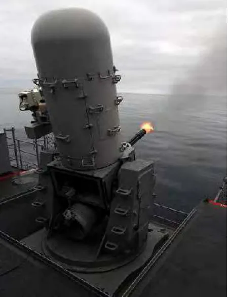
While the idea of an autonomous turret isn't new, nothing has been antecedently developed to be used on this scale. According to (Raytheon, Z.A, 2014),the sole similar system is that the Phalanx Close-In weapon, made by Raytheon. Figure 1.1 show the Phalanx turret mount on the naval ship yard. This method is employed on massive military service vessels as a defense against missile threats. It verify motion and tracks incoming missiles employing a high-powered radio detection and ranging system and so engages these targets with its integral cannon. This method weighs fourteen, 500 lbs, attracts 70kW of power, and price many million ringgit. The Phalanx is incapable of the sort of operation that the system is meant for.
3
1.2Problem statement
In normal practice, human operator are required to stay on full alert during sentry operation. Fatigue and loss of concentration are two main enemy of human operator. Due to that an autonomous system capable of performing the same task is required. Current sentry platform normally too rigid and not flexible to change. This will limit the type of deterrent agent can be mounted on the platform. The software used to control the system also does not provide enough flexibility in the age of internet of things we are living in right now.
1.3 Objective
The purpose of this project is to develop a viable proof-of-concept prototype of the Camera Guided Sentry Turret System
1.4 Scope
The scope of this project had been categorized as listed below I. To develop two axis motion platform
4
CHAPTER 2
LITERATURE REVIEW
This section basically explains about the ideas in designing a turret mechanism based on existence parts and components. This study focused on designing and analyses hardware of camera guided turret system mechanism.
2.1 Overview
5
2.2 The study and research of microcontroller
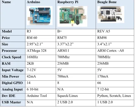
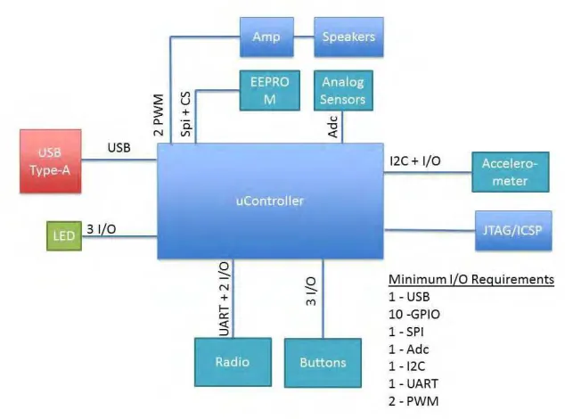
Selecting the proper microcontroller for a product may be according the specify task. Based on Table 2.0 the listed microtroller which is arduino, raspberry pie and beagle being analyze for advantage and disadvantages. The desired microtroller can determine by the look a list of required hardware interfaces (Augarten, Stan, 2012). Using the overall hardware diagram, select an inventory of all the external interfaces that the microcontroller can supportThese two interface sorts can estimate the quantity of pins that may be needed by the microcontroller. Figure 2.1 shows a generic example of a diagram with the I/O and hardware listed.
Table 2.1: List of microcontroller
Name Arduino Raspberry Pi Beagle Bone
Model R3 B+ REV A5
Price RM 60 RM75 RM98 Size 2.95”x2.1” 3.37”x2.2” 3.4”x2.1”
Processor ATMega 328 ARM11 ARM Cortex –A8 Clock Speed 16MHz 700Mhz 700MHz
RAM 2KB 256MB 256MB
Input Voltage 7-12V 5V 5V Min Power 42mA 700mA 170mA Digital GPIO 14 8 66 Analog Input 6 10-bit N/A 7 12-bit
6
Figure 2.1: List of Hardware Features
7
2.3 The study of DC electric motor
DC electric motor capable of generate a mechanical movement. This motor typically converting energy. Based on Figure 2.2 motor were supply with electrical energy and produced mechanical energy (R. Valentine, 2010). Generally DC electric motor used to power variety of devices everyday. It comes in different specification of capability. DC motor operate by direct current.
Figure 2.2: Electric motor power conversion (R.Velentine, 1998)
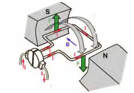
The principle of electric motor movement are coil in the magnetic field as shown in Figure 2.3. The current flows when both end coil connected across DC voltage source when the coil interact it produced the force between interaction of magnetic field and electric current (R. Valentine, 2010).
8
According to Lenz’s law counter-voltage tends to oppose the very cause due to the current. The force created by the magnetic field (F = Bil) equals the load force acting on the shaft. Constant velocity moves the system.
2.3.1: Servo motor
A servo system, or servo, is an automatic device that uses error sensing negative feedback to correct the performance of a mechanism. The term is properly applied solely to systems wherever the feedback or error correction signal helps to regulate a selected parameter of the mechanism. Attributable to their helpful operate, servo mechanisms were used long time ago, the Greek were the one who explore to use of servo. They have used by adjusting the heading of the windmill (Edward L. Owen, 2010). In 1868 Farcot
in his work on hydraulic steam engines for ship steering used the term “Le-Servomoteur” for the primary time. a number of years later H. Calendar developed his initial electro servo mechanism and in 1911 Henry state capital outlined the term “servo-motor” in his technology wordbook (Liu Yu-Cheng, Zhou Yajun. 2011).
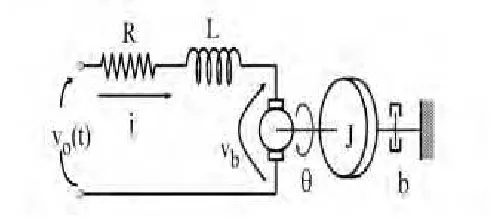
Servo motor are system consists of part categorized into mechanical and electrical, diverse parts are integrated on to perform the utilization of the servomotor. Figure 2.4
bellow shows a typical model of a servomotor system
9
It’s clear that the servomotor has two main parts, the first is that the electrical component; it consists of resistance, inductance, input voltage and so the back electrical phenomenon. The second a part of the servomotor is that the mechanical half, from that it have a tendency to tend to urge the useful mechanical motion movement at the shaft. The mechanical parts are the motor’s shaft, inertia of the motor and inertia and damping. Refers to the position of the output shaft which could be used later to find out the angular speed of the shaft. DC Servomotors have good torsion and speed characteristics; and power is required to be controlled by variability the voltage signal link to the (I/O Liu Yu-Cheng, Zhou Yajun. 2011). These characteristics ready to produce powerful actuators used to move and rotate.
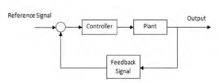
DC Servo motors are DC motors that are changed to figure employing a closed-loop system management system during which the shaft position or angular velocity are the control part. Either digital or analog controller will be accustomed direct the operation of the servo motor by causing position or velocity program signals to the electronic part that drives the motor (Hawkins,Audel. 2012). Figure 2.5 show the structure of servo that
have a feedback function. An integral feedback device (resolver) or devices (encoder or tachometer) are either incorporated within the servo motor or are remotely mounted, usually on the load itself. These devices provide the servo motor’s position and rate feedback to the controller, that successively twenty two use these information to check them with a programmed motion profile and use them to alter the speed signal.
10
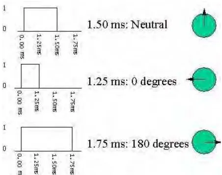
Basically the power apply to the servo motor are proportional to the distance motor travel (Hawkins,Audel. 2012). The larger shaft distance turn, the faster motor run with speed. When the speed turn in small distance, the speed of motor is slower. To communicate servo with turn, wire is used to control the angle. The pulse duration that are applied to the wire will determine the servo angle based on Figure 2.6. Normally the pulse of servo expected in every 20 milliseconds. The motor turn based on how the length on of the pulse applied. 90 degree position or also known as neutral position will turn in 1.5 millisecond. The motor turn back to 0 degree when pulse applied is shorter than 1.5 ms. If more than 1.5ms the motor turn of degree with closer to 180 degree.
Figure 2.6: Pulse dictates the angle of the output shaft (XU Yanping, 2002)
11
2.3.2 Stepper Motor
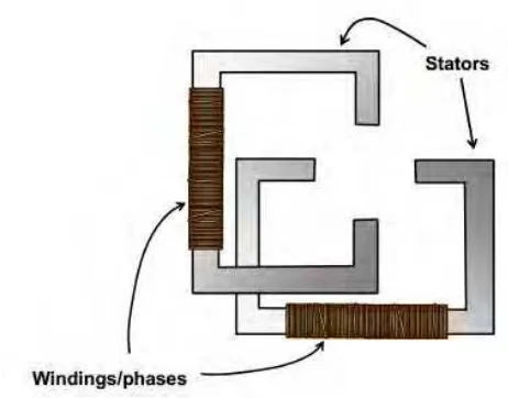
There are a number of components used in order to build this stepper motor. In order to understand the functioning of this equipment different components that are used to build up this equipment. Stepper motors are viewed as the electric motors without commutators. Commutator is a rotary electrical switch in certain types of electric motors or electric generators that periodically reverses the current direction between the rotor and the external circuit. A commutator is a common feature of direct current rotating machines (Harley H.M. 2009). Figure 2.7 show the main component used in the stepper
motor. In a motor all the winding are part of starter. The rotor is a permanent magnet or a tooth block of some magnetically soft material. The motor controller should handle all the commutation extremely. Audio frequencies are used to step most of the stepper motors. In such cases they spin quickly. They can be stopped and started at controlled orientations. Stepper motors are used in simple open loop control systems, suitable for the systems operating allow accelerations with static loads. A stepper over-torqued in an open loop system will result in losing all knowledge of rotor position and a re-initialization of system is required.