UNIVERSITI TEKNIKAL MALAYSIA MELAKA
IMPROVEMENT OF SHIMLESS FOOTING SYSTEM
This report submitted in accordance with requirement of the Universiti Teknikal Malaysia Melaka (UTeM) for the Bachelor Degree of Manufacturing Engineering
(Manufacturing Design) with Honours.
by
NORHIDAYAH BINTI MOHAMED HUSSIN
UNIVERSITI TEKNIKAL MALAYSIA MELAKA
1. Laporan PSM adalah hak milik Universit i Teknikal Malaysia Melaka dan penulis.
2. Perpust akaan Universit i Teknikal Malaysia Melaka dibenarkan membuat salinan unt uk t uj uan pengaj ian sahaj a dengan izin penulis.
3. Perpust akaan dibenarkan membuat salinan laporan PSM ini sebagai bahan pert ukaran ant ara inst it usi pengaj ian t inggi.
**Sila t andakan (√)
** Jika Laporan PSM ini SULIT at au TERHAD, sil a l ampirkan surat daripada
pihak berkuasa/ organisasi berkenaan dengan menyat akan sekal i sebab dan t empoh l aporan
DECLARATION
I hereby, declared this report entitled “Improvement of Shimless Footing System” is the results of my own research except as cited in references.
APPROVAL
This report is submitted to the Faculty of Manufacturing Engineering of UTeM as a partial fulfillment of the requirements for the degree of Bachelor of Manufacturing Engineering (Manufacturing Design) with Honours. The member of the supervisory
committee is as follow:
i
ABSTRACT
ii
ABSTRAK
Projek ini bertujuan untuk mengkaji masalah ‘soft foot’ yang menyebabkan susunan system pam mesin menjadi tidak lurus. Setelah itu, sebuah peningkatan rekaan sistem kaki yang tidak ber’shim’ akan dipertingkatkan untuk mengatasi masalah ‘soft foot’ ini. ‘Soft foot’ ini terjadi apabila ada jarak di antara kaki pam mesin dan tapak asasnya. Pam mesin ini akan bergerak dari kedudukan asalnya walaupun nat telah diketatkan untuk mengelakkannya. ‘Soft foot’ juga menghasilkan garis tekanan pada mesin kerana kaki yang pendek diikat pada tapak asa dengan menggunakan nat. sekiranya ia tidak diperbaiki, hasil yang dihasilkan menjadi tidak berkualiti. Proses rekaan ini akan menggunakan CAD, iaitu Solidwork. Dengan menggunakan perisian ini, sistem tidak ber’shim’ ini dapat dihasilkan dan diperhatikan untuk memastikan ia boleh mengatasi ‘soft foot’. Sistem ini juga perlu mempunyai tapak asas supaya ia tidak lagi bergantung pada ‘shim’ untuk meluruskan system pam mesin. Rekaan ini memudahkan proses pelurusan dan masalah ‘soft foot’ dapat dikurangkan. Kemudian, selepas system ini telah reka, ia akan di analisis untuk mengkaji kesannya ke atas ‘soft foot’ ketika proses meluruskan. Pemerhatian akan dibuat sama ada system ini berkesan ataupun tidak dibandingkan dengan ‘shim’ biasa. Ada dua cara asas untuk mengesan ‘soft foot’ akan digunakan iaitu ‘frame distortion index’ and ‘the laser soft foot locator’. Ia meramalkan yang masalah ‘soft foot’ boleh dihapuskan dimana ‘misalingment’ tidak akan berlaku lagi.
iii
DEDICATION
To my parents, My PSM supervisor, My family and all of my friends
that involve in this study.
iv
ACKNOWLEDGEMENT
vii
5. RESULTS AND DISCUSSION 55
5.1 Analysis result 55
5.2 Result of prototyping process 58
6. CONCLUSION AND RECOMMENDATIONS 62
6.1 Conclusion 62
6.2 Recommendation 63.
REFERENCES 64
APPENDICES 65
APPENDIXS A : GANNT CHART
viii
LIST OF TABLES
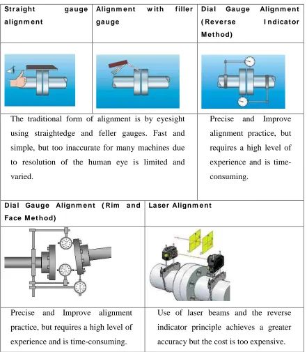
2.1 Comparison correction alignment method 9
4.1 Concept screening 40
4.2 Concept scoring 42
x
4.18 Stratasys FDM 400mc 53
4.19 Inner part with support material 54
5.1 Stress result for main part 56
5.2 Stress result for side part 56
5.3 Stress result for top part 57
5.4 Stress result for inner part 57
5.5 Main part 58
5.6 Screw A 59
5.7 Inner part 59
5.8 Journal bearing 59
5.9 Nut 60
5.10 Side part 60
5.11 Screw B 60
5.12 Assemble parts 61
xi
LIST OF ABBREVIATIONS, SYMBOLS, SPECIALIZED
NOMENCLATURE
CAD - Computer Aided Design USA - United State of America PSM - Projek Sarjana Muda
CNC - Computer Numerical Control
UTeM - Universiti Teknikal Malaysia, Melaka FDM - Fused Deposition Modeling
1
CHAPTER 1
INTRODUCTION
1.1Introduction
Over the past twenty years, the level of awareness concerning the importance of accurate and precise shaft alignment has increased dramatically. In would therefore appear that shaft alignment seems to have taken a more important role when installing and maintaining machinery. Poorly aligned shafts are responsible for many machine problems, studies have shown that incorrect alignment is the cause for around half of machine breakdowns.
2 1.2Overview of the study
In very broad terms, shaft misalignment occurs when the centerlines of rotation of two or more machinery shaft are not in line with each other. So, this study will be discovering the shaft alignment and footing system in industry.
This study is an improvement of shimless footing system. So, in this study supposedly will discover the shaft alignment and soft foot. With Solid Work software and Rapid Prototyping Machine, the new product design will be fine out.
1.3Problem statement
The alignment technician needs to have more general knowledge and skill than simply swinging readings and shimming machine feet, but aligning shaft to be coaxial is a good place to start. (Victor Wowk, 2001).
The other definitely limitation or disadvantages of shim such as material properties that using to construct the shim. Regarding to material properties, influence corrosion factor is very important to keep up the material strength in good condition. Stated that not all type of materials can be used for shimmed the pump.
The bottoms of the machine feet shall rest on the base or foundation with 90 percent contact of the footprint (Victor Wowk , 2000). A 0.003 inch thick shim shall not penetrate under any foot with all hold down bolts loose. This is an unforeseen condition and will require more time to correct (Victor Wowk, 2000). Resonant foundations or bases are dynamic structural defects. This will cause high vibration at specific speeds. Resonances are not detectable during static alignment measurements.
3 1.4Objective of the study
i) To study the shaft alignment and existing shimless footing system. ii) To make an improvement on the current shim footing system design. iii) To propose suitable design and materials.
iv) To give the recommendation and suggestion based on the new product.
1.5Scope of the study
i) To study the current design of shimless footing system ii) To produce conceptual design.
iii) To select the best conceptual design by using appropriate methodology iv) To produce detail design of the selected concept and design specification. v) To test and collect data based on the new design developed.
1.6Significant of the study
The author has found the shaft misalignment occurred when the centerlines of rotation of two or more machinery shaft are not in line with each other. In industry, the shim will be used to perform correction of shaft alignment but in this case, a new design product will be produced to maintain shaft alignment.
1.7Research methodology
4
giving the recommendation. The recommendation based on the result and discussion and it supposedly achieve the objective of this study.
1.8Organizations of reports
5
CHAPTER 2
LITERATURE REVIEW
2.1 Introduction
The purpose of this study is to improve of shimless footing system. In this chapter, reviews and summarization of past studies will be discussed. This literature review shall highlight related arguments, theories, explanations, findings and methodologies from previous research done by researcher worldwide. The sources of this literature review are more come from journal, articles, books, and thesis written by those researchers.
2.2 Shaft alignment
6
The objective in aligning shafts is to get their centerlines coaxial when rotating together under operating conditions. This orientation is presumed to be the one that crates the least amount of distortion in the coupling and the least amount of the undesirable bending in the shafts. This would be a fair assumption if the mechanical components all had perfect geometry.
Advantages of laser alignment
a) The alignment task has become highly automated so that all mechanics can achieve somewhat consistent results. The data from the detectors are streamed directly into a computer, which then proceeds to calculate the movement required. The mechanic does not need to read dial indicators and transfer the values to paper or keyboard. Confusion associated with bar sag, direction conventions, and positive or negative needle swings is eliminated. Less skill is required of the mechanic. The same results could be achieved with electronic gages connected to a computer. b) Bar sag is eliminated. Alignment measurements are possible over longer spans. c) Lasers are the most useful when establishing a line of sight, such as bore alignment,
when the rotors are removed and bearings are to be set collinear. Optical tooling can do the same thing with greater accuracy.
d) Lasers or optics are the most useful in measuring growth changes from cold to hot running. This is done by fixturing a source on one machine housing, and fixturing a detector on the other machine housing or bearing across the coupling. The display is zeroed prior to machine startup. After startup, any immediate changes are mechanical, and slow changes after that are thermally caused.
7
difficulties are encountered, like bolt bound or pipe strain, then the laser provides little or no time advantage.
f) Acceptability criteria. All laser systems have resident in their computers some kind of acceptability criteria that let the mechanic know when the results are good enough and it is time to stop. This also can be done with dial indicators taking the measurements and a computer used for the calculations.
Disadvantages of laser alignment
a) Cost. Laser alignment systems are typically ten times the initial purchase price of dial indicator mechanical systems.
b) Maintainability. The annual calibration fee for laser system is easily $1000. a complete dial indicator alignment system can be purchased for that. Is a laser head is dropped onto a concrete floor and breaks, it could cost approximately $3000 to replace. Forty three dial indicators can be purchased for that cost, at $70 each. Alignment experts agree that it is difficult to recover the initial cost of a laser system, but this maintainability issue makes them reject a laser system even if it is given away for free. Dial indicators can be replaced readily worldwide when in remote locations, and no batteries are required.
c) Safety. Staring directly into the beam can cause permanent eye damage. Also lasers are not intrinsically safe in explosive atmospheres. Since they are an electronic device with an electrical energy source, they could spark an ignition. Dial indicators, however, are intrinsically safe.
d) Both shafts must be rotated together. If one machine cannot be rotated, there are ways of using lasers with sliding brackets, but a dial indicator measurement is superior using the face and rim method.
8