A WIDEBAND OMNIDIRECTIONAL PLANAR MICROSTRIP ANTENNA FOR WLAN APPLICATION USING GRAPHENE
MOHD REDZUAN BIN SHAKIL AHMAD
This Report Is Submitted In Fulfilment of Requirement for the Bachelor Degree of Electronic Engineering (Wireless Communication) With Honors
Faculty of Electronic and Computer Engineering Universiti Teknikal Malaysia Melaka
ii
UNIVERSTI TEKNIKAL MALAYSIA MELAKA
FAKULTI KEJURUTERAAN ELEKTRONIK DAN KEJURUTERAAN KOMPUTER
BORANG PENGESAHAN STATUS LAPORAN
PROJEK SARJANA MUDA II
Tajuk Projek : A Wideband Omnidirectional Planar Microstrip Antenna For WLAN Application Using Graphene
Sesi Pengajian : 1 4 / 1 5
Saya MOHD REDZUAN BIN SHAKIL AHMAD mengaku membenarkan Laporan Projek Sarjana Muda ini disimpan di Perpustakaan dengan syarat-syarat kegunaan seperti berikut:
1. Laporan adalah hakmilik Universiti Teknikal Malaysia Melaka.
2. Perpustakaan dibenarkan membuat salinan untuk tujuan pengajian sahaja.
3. Perpustakaan dibenarkan membuat salinan laporan ini sebagai bahan pertukaran antara institusi pengajian tinggi.
4. Sila tandakan ( √ ) :
SULIT*
*(Mengandungi maklumat yang berdarjah keselamatan atau kepentingan Malaysia seperti yang termaktub di dalam AKTA RAHSIA RASMI 1972)
TERHAD** **(Mengandungi maklumat terhad yang telah ditentukan oleh organisasi/badan di mana penyelidikan dijalankan)
TIDAK TERHAD
Disahkan oleh:
__________________________ ___________________________________
iii
STUDENT DECLARATION
“I hereby declare that this report is the result of my own work except for the quotes as cited in the references”
Signature :………
Author : MOHD REDZUAN BIN SHAKIL AHMAD
iv
SUPERVISOR DECLARATION
“I hereby declare that I have read this report and in my opinion this report is sufficient in terms of the scope and quality for the award Bachelor Degree of Electronic Engineering
(Wireless Communication) With Honors”
Signature :……….
Supervisor Name : Mr. AZMAN BIN AWANG TEH
v
Special dedication to my loving father, Shakil Ahmad Bin Badaruddin and my mother Noor Jahan Binti Izharul Haq, my kind hearted supervisor, Mr Azman Bin Awang Teh, my brother and sister, my dearest friend especially Yully Erwanti Binti Masrukin, Nurul
vi
ACKNOWLEDGMENT
My most sincere thanks go to my supervisor, Mr Azman Bin Awang Teh for his dedication to his student and patience in assisting me with this thesis. I would like to thank to him for his valuable advice and efforts offered during the completion of this thesis.
vii
ABSTRACT
viii
ABSTRAK
ix
TABLE OF CONTENTS
CPAPTER SUBJECT PAGE
PROJECT TITLE i STATUS REPORT DECLARATION FORM ii
STUDENT DECLARATION iii
DECLARATION SUPERVISOR iv
DEDICATION v
ACKNOWLEDGMENT vi
ABSTRACT vii
ABSTRAK viii
CONTENT ix
LIST OF TABLE xi
LIST OF FIGURE xiii
1 PROJECT INTRODUCTION
1.1 Introduction 1
1.2 Problem Statement 6
x
1.4 Scope of Project 7
1.5 Brief Methodology 8
1.6 Thesis Structure 8
2 LITERATURE REVIEW
2.1 Literature Review 9
2.2 Planar Microstrip Patch Antenna 10
2.3 Antenna Characteristic 13
2.3.1 Radiation pattern 13
2.3.2 Antenna Directivity 16
2.3.3 Antenna Gain 17
2.3.4 Return Loss 17
2.4 Operation of Omnidirectional Planar
Microstrip Antenna 18
2.5 Graphene 19
3 METHODOLOGY
3.1 Substrate Material 21
3.2 Parameter Study 22
3.3 Designing Antenna 23
3.4Flow Chart 30
4 RESULT AND DISCUSSION
xi
4.2 Comparing Copper and Graphene As
Patch Material 33
4.2.1 1x4 Copper and Graphene as Patch 33 4.2.1.1 Copper Thickness 0.035mm 36 4.2.1.2 Graphene Thickness 0.355nm 38 4.2.1.3 Graphene Thickness 0.035mm 40
4.3 Optimization of Graphene Design 42
4.3.1 1x4 Patch Graphene 44
4.3.2 1x6 Patch Graphene 47
4.3.3 1x8 Patch Graphene 50
4.3.4 1x10 Patch Graphene 53
5 CONCLUSION AND RECOMMENDATION
5.1 Conclusion 57
5.2 Recommendation 59
xii
LIST OF TABLES
NO TITLE PAGE
2.1 FR4 properties 12
2.2 Comparison between copper and graphene 20
3.1 Design parameter for 1x4 planar microstrip using copper 25 3.2 Design parameter for 1x4 planar microstrip using graphene 26
3.3 Design parameter for 1x4 planar microstrip using 26
thicknesses graphene
3.4 Design parameter for 1x6 planar microstrip using copper 27 3.5 Design parameter for 1x8 planar microstrip using copper 28 3.6 Design parameter for 1x10 planar microstrip using copper 28
4.1 Comparison of thickness 32
4.2 Comparison copper and graphene 35
xiii
LIST OF FIGURES
NO TITLE PAGE
1.1 Type of antenna 4
1.2 Discover graphene 5
2.1 Basic configuration of patch antenna 10
2.2 Side view of patch antenna 11
2.3 Antenna radiation pattern 14
2.4 The radiation pattern for isotropic antenna and
omnidirectional 14
2.5 Radiation pattern for an omnidirectional antenna 15
3.1 Configuration of the proposed antenna 22
3.2 Design of planar microstrip antenna using as patch 25
3.3 Design of 1x4 planar microstrip antenna using graphene 25
3.4 Design of 1x4 planar microstrip antenna using graphene
0.355nm thickness 26
3.5 Design of 1x6 planar microstrip antenna using graphene 27 3.6 Design of 1x8 planar microstrip antenna using graphene
xiv
3.7 Design of 1x10 planar microstrip antenna using graphene
as patch 28
3.8 CST 2011 Studio Suite Software 29
4.1 Return Loss substrate thickness 0.8 mm 32
4.2 Return Loss substrate thickness 1.6 mm 32
4.3 S11 parameter, return loss and bandwidth for copper
material with 0.035mm thickness 36
4.4 Gain for copper 0.035 mm thickness 36
4.5 Realized gain for copper 0.035 mm thickness 37
4.6 Directivity for copper 0.035 mm thickness 37
4.7 S11 parameter, return loss and bandwidth for graphene
material with 0.035mm thickness 38
4.8 Gain for graphene 0.035 mm thickness 38
4.9 Realize gain for graphene 0.035 mm thickness 39
4.10 Directivity for graphene 0.035 nm thickness 39
4.11 S11 parameter, return loss and bandwidth for graphene
material with 0.355nm thickness 40
4.12 Gain for graphene 0.355 nm thickness 40
4.13 Realize gain for graphene 0.355nm thickness 41
4.14 Directivity for graphene 0.355 nm thickness 41
4.15 S11 parameter, return loss and bandwidth for 1x4 patch
graphene Material 44
4.16 Gain for 1x4 patch graphene 45
xv
4.18 Directivity for 1x4 patch graphene 46
4.19 y-z Plane Radiation Pattern for 1x4 Patch Graphene 46
4.20 x-y Plane Radiation Pattern for 1x4 Patch Graphene 47
4.21 S11 parameter, return loss and bandwidth for 1x6 patch
graphene material 47
4.22 Gain for 1x6 patch graphene 48
4.23 Realize gain for 1x6 patch graphene 48
4.24 Directivity for 1x6 patch graphene 49
4.25 y-z plane radiation pattern for 1x6 patch graphene 49 4.26 x-y plane radiation pattern for 1x6 patch graphene 50 4.27 S11 parameter, return loss and bandwidth for 1x8 patch
graphene materials 50
4.28 Gain for 1x8 patch graphene 51
4.29 Realize gain for 1x8 patch graphene 51
4.30 Directivity for 1x8 patch graphene 52
4.31 y-z plane radiation pattern for 1x8 patch graphene 52 4.32 x-y plane radiation pattern for 1x8 patch graphene 53 4.33 S11 parameter, return loss and bandwidth for 1x10 patch
graphene material 53
4.34 Gain for 1x10 patch graphene 54
4.35 Realize gain for 1x10 patch graphene 54
4.36 Directivity for 1x10 patch graphene 55
4.37 y-z plane radiation pattern for 1x10 patch graphene 55
Chapter 1
Introduction
1.1 Introduction
2
broadcast radio or televisions, Bluetooth, satellite communications and many more that have the same properties as those in its operation.
Antennas consist of metallic conductors connected to receiver electrically through transmission line. An oscillating current of electrons forced through the antenna by a transmitter will create an oscillating magnetic field around the antenna elements, while the charge of the electrons also creates an oscillating electric field along the elements. There can be a connection between transmitter and receiver which serve direct radio waves into a beam or any other pattern such as reflective elements. Sometimes antenna that is fully equipped with a device will be hidden such as antennas in cell phones or laptop. [1]
3
(a) Parabolic antenna
(b) Dipole antenna
4
[image:19.612.222.433.69.204.2](d) Whip antenna
Figure 1.1: Type of antennas
Basic antennas such as dipole and vertical design are less used in nowadays as technology rapidly growth. Complex antenna has been developed to increase the directivity and the gain of the antenna. Gain of the antenna can be described as the radiated power in a particular angle of space as in spherical radiation. Power has to be maintaining at the desired direction as there is no increasing power at transmitter. Grounding for antennas is a structure of conductive element. To have proper functions, it need to have natural ground that well functioned. Impedance matching is a between the antenna and transmitter or receiver. To reduce losses in transmission, standard resistive impedance are needed to operate at its optimum operation as to improve the standing wave ratio (SNR) of the antenna [1].
5
and many more required in wireless as in borderless world nowadays. Thus, in this new era, it required an antenna that can perform better and less cost in producing it.
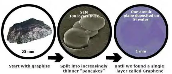
[image:20.612.186.472.268.391.2]Graphene are the substrate that will revolutionized this century as the greatest conductor. Graphene is a 2 dimensional of single layer carbon atoms. It is the thinnest and yet as the strongest material on earth where it about 200 times stronger than steel. It can conduct electric and heat efficiently. Graphene almost transparent and so dense until the smallest atom in periodic table which is helium cannot pass through it.
Figure 1.2: Discovering graphene
6
Other than electronic properties, graphene has extraordinary properties in mechanical strength. Graphene has been known as the strongest material has been discovered nowadays left behind diamond and steel. Approximately about 130,000,000,000 Pascal compared to 400,000,000 for structural steel or 375,700,000 for Aramid substance that been used to build Kevlar. Even though graphene has this strength, it only 0.77 milligrams per square meter and is 1000 times lighter than one square per meter of paper. Graphene also has elastic properties even after being strain. [5]
1.2 Problem Statement
7
1.3 Project Objective
To make sure this project work as planned, a few objectives were determined where these objectives will be followed as a guide through the whole completion process of this project in order to achieve the desired output. These objectives were provided by sequence of project from beginning until the end of project. A detailed explanation for each objective will be discussed. There are several objectives that are to be achieved at the end of the project which includes:
1) To design 1x4, 1x6, 1x8 and 1x10. Omnidirectional Planar Microstrip antenna using Graphene and design it using CST Microwave studio software. 2) To compare the performance of copper and graphene as conductor for A
Wideband Omnidirectional Planar Microstrip Antenna for WLAN Application.
3) To optimize the design the antenna design.
1.4 Scope
As to ensure the completion of project achieves the stated objectives, the project shall be completed within these scopes:
1) Focus on 1x4, 1x6, 1x8 and 1x10. Omnidirectional Planar Microstrip antenna using graphene as material.
2) Simulation using CST Microwave Studio software. 3) Target frequency from 2.4 GHz.
4) To compare performance of 1x4 coppers as patch material versus 1x4 graphene as patch material.
8
1.5 Brief explanations on methodology
To achieve the goal that has been set in the objectives of this project, there are so many works that need to be done. The first stage is learning the concept of microstrip patch antenna and electronics properties of graphene and how the implementations in antenna. The next stage are designing and simulating the antennas model in CST software. Finally, compare and analyze the performance of the antennas. A detail explanation for the parts will be explained in Chapter 3.
1.6 Report organizations
In this report, there are 5 chapters which are introduction, literature review, methodology, result and conclusion and discussion. Not included in chapter is a reference, abstract, table of content, table of picture and appendices.
Chapter one shows the introduction of this project. It contains the background of the project and briefly explanation about the project methodology.
Chapter two consists of literature review of project. It covers the study of the project such as the basic information of antenna, planar microstrip antenna, basic information of graphene, and electronic properties of graphene that used in the project for the future plan.
Chapter 2
Literature Review
2.1 Literature Review