ON FUNDAMENTAL EVALUATION USING UAV IMAGERY AND 3D MODELING
SOFTWARE
K. Nakano a, d *, H. Suzuki b, T. Tamino c, H. Chikatsu d
a
Geospatial laboratory, Product Planning Department, AERO ASAHI CORPORATION, b UAS Promotion Section, Sales Planning Department, AERO ASAHI CORPORATION, c
Research and Development Center, Product Planning Department, AERO ASAHI CORPORATION,
3-1-1, Minamidai, Kawagoe, Saitama, 350-1165, Japan - <kazuya-nakano>< hideo-suzuki>< takaomi-tamino>@aeroasahi.co.jp d
Division of Architectural, Civil and Environmental Engineering, Tokyo Denki University, Ishizaka, Hatoyama, Saitama, 350-0394, Japan - [email protected]
Commission V, WG V/1
KEY WORDS: UAV, Modeling, Photogrammetry, Structure from Motion / Multi-View Stereo, Accuracy evaluation
ABSTRACT:
Unmanned aerial vehicles (UAVs), which have been widely used in recent years, can acquire high-resolution images with resolutions in millimeters; such images cannot be acquired with manned aircrafts. Moreover, it has become possible to obtain a surface reconstruction of a realistic 3D model using high-overlap images and 3D modeling software such as Context capture, Pix4Dmapper, Photoscan based on computer vision technology such as structure from motion and multi-view stereo. 3D modeling software has many applications. However, most of them seem to not have obtained appropriate accuracy control in accordance with the knowledge of photogrammetry and/or computer vision. Therefore, we performed flight tests in a test field using an UAV equipped with a gimbal stabilizer and consumer grade digital camera. Our UAV is a hexacopter and can fly according to the waypoints for autonomous flight and can record flight logs. We acquired images from different altitudes such as 10 m, 20 m, and 30 m. We obtained 3D reconstruction results of orthoimages, point clouds, and textured TIN models for accuracy evaluation in some cases with different image scale conditions using 3D modeling software. Moreover, the accuracy aspect was evaluated for different units of input image—course unit and flight unit. This paper describes the fundamental accuracy evaluation for 3D modeling using UAV imagery and 3D modeling software from the viewpoint of close-range photogrammetry.
* Corresponding author
1. INTRODUCTION
Unmanned aerial vehicles (UAVs) have many applications in various fields such as archaeology (Verhoeven, 2011), agriculture (Honkavaara et al., 2012), and mining (Tscharf, 2015). Moreover, use of 3D modeling commercial software based on structure from motion/multi-view stereo (SfM/MVS) has considerably increased in recent years. Therefore, accuracy evaluation of 3D modeling software in some cases has been performed (Necerino et al., 2013, Strecha et al., 2015). Naturally, previous studies selected the focus of the camera to enable high-accuracy photogrammetry. However, auto-focus is expected to be used in low-altitude flights for obtaining images for practical topographical mapping.
On the other hand, the authors have been focusing on 3D measurement systems using consumer-grade digital cameras for the various application fields (Nakano and Chikatsu, 2010). It was concluded that the evaluation of the interior orientation parameter in the self-calibration process is important for high-accuracy close-range photogrammetry using non-metric digital cameras.
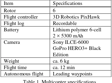
To this end, we performed a fundamental study on practical image acquisition in low-altitude flights and the accuracy evaluation of 3D modeling from the viewpoint of close-range customized model ZION Pro800 of the multirotor manufactured by ENROUTE CO., LTD., JAPAN. Table 1 lists the
The multicopter can autonomously fly according to waypoints of the flight plan in the mission planner of the open source software. The flight speed can be selected at 0.5 m/s intervals, for example, 2.0 m/s, 2.5 m/s.
Figure 1 shows the multicopter on the temporary take-off and landing field. Sony ILCE-6000 with gimbal equipment under the body of the multicopter can be observed.
Figure 1. Muticopter on the take-off and landing field
3. TEST FIELD
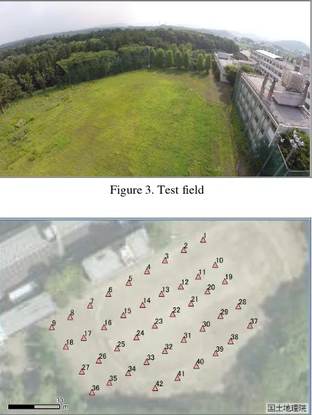
In Japan, the aviation law for UAVs has been partially revised in December 2015. Therefore, free flight of the UAV has become more difficult. We borrowed the Robot Field Experiment Facility from Saitama Prefecture as part of the leading-edge project. The field is a ground which was shut down in March 2013. Therefore, the ground was overgrown with rank weeds. The location and conditions of the fields are shown in Figure 2 and Figure 3, respectively. The weeds can be observed in Figure 3.
Figure 2. Test field location
Figure 3. Test field
Figure 4. Configuration of test target
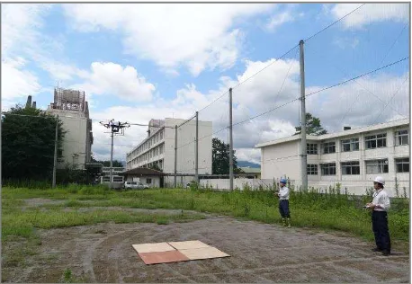
The weeds are approximately 20 cm in height, including the height of about 1 m. A tether for UAV getaway prevention was employed as a safety measure in the field. The flight status using the tether is shown in Figure 5 and Figure 6. The flight operator, tether operator, and UAV connected with a tether can be seen in Figure 5. The temporary take-off and landing field can be seen in the lower center of Figure 5. It was placed as a safety measure to reduce the influence of dust by downwash during take-off and landing. The tether connected to the right skid of the UAV to fly toward the left direction can be confirmed in Figure 6.
The test targets were placed at 42 points in an area of about 90 × 70 m on the ground for accuracy estimation, as shown in Figure 3 and Figure 4. The test target is a black-and-white target of dimensions 8 × 8 cm, and the local coordinates were observed using a total-station (Leica Geosystems, TCR703). The local coordinates were converted to geodetic coordinates using a GNSS (Leica Geosystems, GS10). The total-station has a distance measuring accuracy of 2 mm + 2 ppm and an angle measuring accuracy of 3 s.
Figure 5. Flight conditions
Figure 6. UAV with a tether
4. CONDITIONS OF IMAGE ACQUISITION
A consumer grade mirror-less single-lens reflex camera mounted on the UAV was used in the measurement. The transmitter of the UAV can control the camera shutter, and shooting intervals of 2 s or 5 s can be set manually. A flight speed of 2 m/s and a shooting interval of 2 s were set in the flight plan in consideration of the conditions of the multicopter and digital camera. The overlap rate is affected by the flight altitude because the flight speed and shooting interval are fixed. Table 2 shows the digital camera specifications. For close-range image acquisition, the flight altitude was set at 10 m, 20 m, and 30 m. The flight plan specifications for altitude are shown in Table 3. It can be seen that the high-resolution ground sampling distance was 2.4–7.3 mm.
The baseline length was 4 m, and the flight speed was selected to be 2 m/s for a shooting interval of 2 s; the overlap rate calculated from the footprint is also shown in Table 3.
Although the overlap rate was calculated to be less than 59% at an altitude of 10 m, it was estimated that 3D reconstruction is possible under 18% overlapping in triplet images considering the requirements of the input image of the 3D modeling
Altitude GSD Foot print Overlap 10 m 2.4 mm 14.6 × 9.8 m 59% 20 m 4.9 mm 29.3 × 19.5 m 79% 30 m 7.3 mm 43.9 × 29.3 m 86%
Table 3. Image acquisition specifications
5. MODELING HYPOTHESIS
3D modeling software has been widely used in recent years. It is possible to reconstruct relative models by extracting a large number of multidimensional features from high-overlap images without ground control points.
The exterior orientation parameter in the 3D modeling software is calculated utilizing computer vision techniques based on SfM. SfM can reconstruct 3D space by overlapping the images from different perspectives. The number of courses and exposure stations and placement of ground control points are determined in accordance with the working area for quality control of map plotting or orthoimage creation in photogrammetry. In other words, a 3D model with accuracy is expected to easily combine the modeling process in computer vision and the flight planning in photogrammetry.
On the other hand, considering that images are taken at a fixed interval and multiple images are feature matched in SfM, the image redundancy must be greater than that in the image dataset of traditional photogrammetry in order to acquire a better image dataset.
Therefore, in this study, the accuracy was compared to obtain course units and flight units of the models.
6. IMAGE ACQUISITION
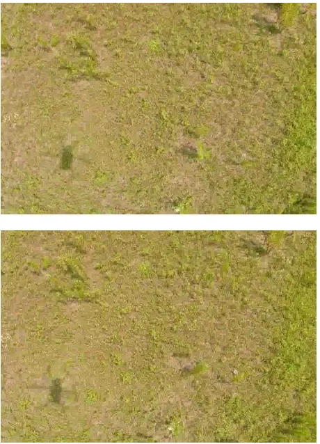
Autonomous flight tests were performed in accordance with the flight plan in the test field. As a result, the dataset for a 10 m flight altitude was judged unsuitable for analysis. The images were not suitable for stable image matching because the surface of the vegetation was moving because of the wind from the
UAV’s downwash. It was considered that reasonable evaluation is difficult because of the motion of the surface of the vegetation and insufficient overlap rate. The strong downwash was caused by the UAV weight of approximately 6 kg. Figure 7 shows the motion of the vegetation because of the downwash at a 10 m flight altitude. We used two image sensors—Sony ILCE-6000 and GoPro HERO3+ Black Edition. The motion of the vegetation is difficult to detect in the interval still images of Sony ILCE-6000 for photogrammetry. The motion of the vegetation became apparent in the moving images of GoPro HERO3+ Black Edition for situation understanding. The motion of the vegetation was not detected in images obtained from flight altitudes of 20 m and 30 m.
Figure 7. Motion of vegetation
7. ACCURACY EVALUATION
We used three 3D modeling softwares—Acute3D Smart3Dcapture, Pix4Dmapper, and Photoscan. Pix4Dmapper was used for accuracy evaluation in this study because it has been empirically understood that the softwares have no significant differences in accuracy, although their price and interfaces are different. A 3D model was constructed by self-calibration using five ground control points (GCPs) (1, 9, 22, 36, 37 in Figure 4), and the nominal values of the camera specifications. The approximate positions of the exposure station are given by the flight log of the UAV using a GNSS. Therefore, accuracy evaluation was performed using the processing combination of course unit/flight unit and GNSS/GNSS + GCPs, as shown in Table 4. however, plannimetric accuracy was observed using orthoimage and height accuracy computed by the inverse distance weighted method using the point cloud. Table 5 and Table 6 show the RMSE for check points.
Altitude Course unit Flight unit
σxy [m] σz [m] σxy [m] σz [m]
20 m 0.899 4.420 0.470 4.479
30 m 1.420 3.769 1.065 3.706
Table 5. Accuracy for a given condition of GNSS
Altitude Course unit Flight unit
σxy [m] σz [m] σxy [m] σz [m]
20 m 0.581 0.682 0.015 0.022
30 m 0.008 0.022 0.009 0.024
Table 6. Accuracy for a given condition of GNSS + GCPs
Table 5 shows that the height accuracy for a given condition of GNSS was about 4 m. It was inferred that influence of the single point positioning error of GNSS. Moreover, the planimetric accuracy shows an RMSE of 0.5–1.4 m.
On the other hand, the results for the given conditions of GNSS and GCPs confirm that the horizontal accuracy and height accuracy are about 2 cm, except for the result for a course unit of 20 m in Table 6. However, planimetric accuracy shows a lower value than one pixel of plan specifications of the ground sampling distance (4.9 mm at a flight altitude of 20 m, 7.3 mm at a ground altitude of 30 m); therefore, the pointing accuracy is regarded as the standard error.
The results for the course unit at a flight altitude of 20 m for given conditions of GNSS and GCPs showed an accuracy remarkably lower than that of the other results. It was surmised that the number of GCPs must be reduced when selecting the strong downwash and vegetation motion. Two image sensors were effective for acquiring images for topographic mapping and situation understanding.
Planimetric accuracy and height accuracy using the auto-focus setting has achieved 2 times from 4 times of ground sampling distance.
As a result, UAVs can acquire high-resolution images at low-altitude flights with auto-focus settings. It was understood that a combination of different conditions must be considered from the viewpoint of accuracy control. The accuracy evaluation results were obtained in centimeters. Further studies are required because this accuracy is insufficient from the viewpoint of photogrammetry.
photographs with photoscan. Archaeological Prospection, 18 (1) , pp. 67-73.
Honkavaara, E., Kaivosoja, J., Makynen, J., Pellikka, I., Pesonen, L., Saari, H., Salo, H., Hakala, T., Markelin, L., Rosnell, T., 2012. Hyperspectral reflectance signatures and point clouds for precision agriculture by light weight UAV imaging system. ISPRS Annals of the Photogrammetry, Remote Sensing and Spatial Information Sciences, I-7, pp.353-358.
Tscharf, A., Rumpler, M., Fraundorfer, F., Mayer, G., Bischof, H., 2015. on the use of uavs in mining and archaeology - geo-accurate 3d reconstructions using various platforms and terrestrial views, ISPRS Annals of the Photogrammetry, Remote Sensing and Spatial Information Sciences, Toronto, Canada , Vol. II-1/W1, pp.15-22.
Nocerino, E. , Mennaa, F. , Remondino, F., Saleri, R., 2013. accuracy and block deformation analysis in automatic uav and terrestrial photogrammetry - lesson learnt -, ISPRS Annals of the Photogrammetry, Remote Sensing and Spatial Information Sciences, Vol. II-5/W1, pp.203-208.
Strecha, C., Zoller, R., Rutishauser, S., Brot, B., Schneider-Zapp, K., Chovancova, V., Krull, M., Glassey, L., 2015. quality assessment of 3d reconstruction using fisheye and perspective sensors, ISPRS Annals of the Photogrammetry, Remote Sensing and Spatial Information Sciences, Munich, Germany, Vol. II-3/W4, pp.215-222.
Nakano, K., Chikatsu, H., 2011. Camera-variant calibration and sensor modeling for practical photogrammetry in archeological sites. Remote Sensing. Vol.3, pp.554–569.