No. 28 Vol.1 Thn. XIV November 2007 ISSN: 0854-8471
TeknikA
75
ESTIMATION OF BEARING CAPACITY
OF FLOATING RAFT-PILE
Abdul Hakam
School of Civil Engineering - UNAND
ABSTRACT
In this paper, the total bearing capacity estimation of floating raft-pile system subjected to axial loading is presented. The proposed analysis is based on the conventional formulas and the foundation prototypes tested in laboratory. The given axial load and vertical displacement of the models are recorded. The net ultimate capacity for every single pile is predicted from load-displacement curves resulting from the tests. The axial load tests of individual raft foundations are also carried out. The group of the piles are then pushed to obtain the load-displacement curve of the foundation. Finally, the raft pile foundation is tested in the same way. In this paper, analytical formulas to estimate the axial pile capacity and the group piles efficiency for piles in clay is reviewed. The calculation using the formulas is compared to the laboratory tests. The axial capacity of the raft-piles foundations floating in clays can be concluded higher than the combination of the piles and the raft capacities. For practical application, the combination formula to estimate the total floating foundation load capacity in soft clay is proposed.
Keywords: Raft-pile system, floating foundation, bearing capacity
INTRODUCTION
In this study, the effects of the individual piles and the cap to the pile group bearing capacity are elaborated. The term of the group efficiency formula is nevertheless used to outline the load capacity of each element composed a raft-pile foundation. The suggestion procedures for estimating load capacity of the raft-pile system floating in soft clays are outlined.
More recently, the analysis of load capacity of the raft piles floating in soft clay has been studied (Hakam et all, 2005). In this study, a number of load test series are conducted to the raft-piles models in laboratory. It is concluded that the efficiency of the pile group in the raft-pile system can reach higher than 100%. Then based on this studied, it is he suggested to use the total capacity of floating raft piles that are including the capacity of the raft and the piles.
When a group of piles is made up of several individual piles, the load capacity of the group cap may not be the same as the sum of the load capacity piles. The effect of grouping the piles arises the different amount of the group capacity and the sum of the individual contributing piles in term of efficiency of the pile group. Based on the studies done in the past, a number of references have suggested the formulas to estimate the pile group efficiency (ex. Das 1990, Bowles 1988). However, the formulas do not include the effect of the cap which plays the important roles to group the piles. Even the pile cap commonly poured directly on the ground, the effect of the cap to transfer the load to
the underneath soil was ignored. Except for piles in rock, Bowles (1988) suggested the use of the virtual block capacity based on the shear around the block plus the block bearing point instead of sum of the capacity of the piles. Then, Das (1990) recommended adopting the lower values between those two amounts as the ultimate load of the group.
The total load of the pile group involving the contribution of the cap using the numerical simulation has been purposed by Valliappan et al (1999). The pile groups including the effect of the cap transfer the load were then defined as the Raft-pile foundations. In this study, the raft-Raft-pile foundations are formed as a solid structure. Then the effects of each element forms the foundation can not be figured. However in the practice, the foundation is made of number of single piles which individually has a load capacity and a cap on the ground.
LOAD CAPACITY OF A SHALLOW RAFT IN CLAY
When the shallow raft foundation is supported by a fairly soft soil, the failure surface in the soil will not extend to the ground surface. Such a failure type can be identified as the punch failure. Terzaghi has presented a comprehensive theory for evaluation the load capacity of shallow foundation. Here, the formula is then employed to estimate the bearing capacity of a raft foundation.
The general expression of the ultimate load capacity is in the form;
No. 28 Vol.1 Thn. XIV November 2007 ISSN: 0854-8471
TeknikA
76
where Cu is undrained cohesion soil strength at the foundation base, Ab is the cross section area of the foundation and Nc
*
is the bearing capacity factor. The value of Nc is vary depending on the internal friction angle of the soil. For undrained shear strength of saturated clays with zero internal friction angle, the factor is 5,14 ( After Das, 1990). Ft is the factor expresses the type of the shear failure type of the soil under the foundation. For the general shear failure of square footing is considered, the Ft is equal to 1,3 and for the local shear failure considered, then it is 0,867. Then, for strip foundation, the value is reduced by the factor of 0,77. If the punched shear failure is considered, the Ft value must be less than those values. In the last section of this paper, the value Ft for punch failure is discussed.
For practical purpose, the net allowable bearing capacity of raft foundations in undrained saturated clay can be expressed in the form;
Qall = Fd Ab Cu
where Fd is a factor depend on the depth-width ratio, it is 1 for foundation on ground surface and equal to 3 for the depth-width ratio of 3,0. The safety factor of about 3 is used to set up the above formula. However, the above formula is not recommended for foundations in soft clay.
ULTIMATE LOAD CAPACITY OF PILE GROUPS
The ultimate axial load capacity of group piles in clay can be estimated using the general procedures as follow:
Firstly, determine the total load of the piles which includes the point capacity on the pile tip and skin friction resistances:
QT1 = Σ (QP + QS)
If the number of the pile in a square group in one direction is n1 and n2 in the other way, the by substituting the end capacity of pile and the skin friction formulas, the total load can be written as:
QT1 = n1n2 [ AP Cu(p) Nc+ Σ ( Cu L)]
where Cu(p) is the undrained cohesion of the clay at the pile tip and Cu is at the skin of the piles.
Secondly, determine the ultimate capacity of the group piles by assuming as solid block foundation. The dimension if the virtual block is Lg and Bg for horizontal direction and L (equal to the pile length average) for vertical one. Then by adopting the equation for individual pile capacity, the total load of the block is in terms of:
QT2 = AB Cu(p) Nc + Σ 2(Lg+Bg) Cu L
Finally, the lower of the two values is referred to the ultimate load of the group QT(g).
EFFICIENCY OF PILE GROUPS
When several piles bonded by a cap in a group, the load capacity may be different from the sum of the several individual pile loads. If the total load at the cap is equal to sum of the individual pile loads, the efficiency of the group, Eg, is equal to 1. Then, the general definition of the pile group efficiency is;
capacity pile individual the
of sum the
capacity group the Eg=
For rectangular group of friction (floating) piles with the number of pile n in row and m in column, the Bridge Specifications of AASHTO suggests to estimate the efficiency of the pile groups as;
mn 90
1)n -(m 1)m -(n θ -1
Eg
+ =
Where
θ
= tan-1 D/s in degrees, D is the diameter of individual pile and s is the centre-to-centre spacing.PROTOTYPE TEST
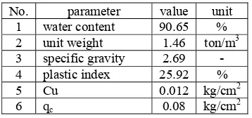
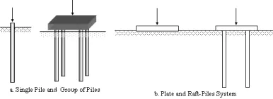
In this study, a number of wood and concrete pile models are tested. There are four models typically tested to obtain the load-displacement curve of the system as shown in the Figure 1. In the laboratory, the soil is put in to the box and merged under the water table. The soil is silty clay soil ( 50 % clay, 49 % silty and 1 % sand) with the parameters as shown in the table 1. In this report, the piles and the plate are made of concrete. Since the clay is soft, the strength and the elasticity of the piles and the plate materials are assumed to be much stiffer than the soil. Then the behaviour of the soil-foundation system depends on the entire system than the material of the structures. The pile is 1.5 cm in the diameter and 30 cm of length. The centre to centre space of piles in group is 7.5 cm which is equal to 5 times the diameter of the piles. The wooden plate is 15 cm x 5 cm, the concrete plate is 15 cm x 15 cm of the area and 2 cm of the thicknesses.
Table 1 The Soil Parameters
No. parameter value unit 1 water content 90.65 % 2 unit weight 1.46 ton/m3 3 specific gravity 2.69 - 4 plastic index 25.92 % 5 Cu 0.012 kg/cm2 6 qc 0.08 kg/cm2
No. 28 Vol.1 Thn. XIV November 2007 ISSN: 0854-8471
TeknikA
77
are drawn subsequently. The ultimate capacity of each single pile can be estimated from load-displacement curves resulting from the tests.
Then, the group of the piles are pushed in the same way in to the clay. The axial load the applied on the centre of the pile group to obtained the displacement curve of the foundation. The load-displacement curves of the pile group are also drawn subsequently. In the same way, the raft pile foundation and the separate plate on the clay are tested.
There are two types of raft-pile system tested in the laboratory, the first is 2x1 wooden raft-pile system sand the other one is 2x2 concrete raft-pile foundation. The procedures used in laboratory for the both foundations are the same.
Figure 1 Laboratory models of the foundation
TEST RESULTS FOR 1X2 WOODEN PILE-RAFT SYSTEM
The results of the tests in the terms of the maximum load and displacement of the models are represented in the Table 2. It shows that the maximum load of the raft is higher than the group of pile. Further more, the maximum value of the raft-pile system is higher that the sum of the piles and the plate. In the other words, the efficiency of the raft-pile system is more than 100 % which is 130 % for these tests (compared to the sum of piles’ capacity). Even the plate only gives small contribution to the total load (max 15 %), the load displacement of the pile is similar to the plate compared to the piles’ one.
Table 2. Resume of the results.
Model : pile (1 + 2) If the efficiency of the raft-pile system is defined as ratio of the system compared to the sum of the individual pile and the raft, the efficiency of the raft-pile system , Erp, is written as:
Using the above equation, the efficiency of the raft-pile system is:
RESULTS FOR 2x2 CONCRETE PILE-RAFT SYSTEM
The results of the tests are presented in the terms of load displacement curves as before. The test results in the terms of load for the raft-pile system are shown in the table 3. The loading test of the plate gives the maximum load of 36.0 and the 135.0 for the raft-pile system. The maximum loads are reached at the displacement of 2.00 mm for the plate. For the raft-pile system, the maximum load is reached at the displacement of 2.10 mm.
The maximum load values of the models are represented in the Table 3. It shows that the
maximum load of the raft is higher than the group of pile and the combinations of the group and the single raft. Further more, the maximum value of the raft-pile system is higher that the sum of the raft-piles and the plate. In the other words, the efficiency of the raft-pile system is more than 100 % which is 167 % for these tests. Even the plate only gives
small contribution to the total load (44 %), the non-dimensional load displacement of the raft-pile system is similar to the plate compared to the piles.
Again, if the efficiency of the raft-pile system is defined as ratio of the system compared to the sum of the individual pile and the raft, the efficiency of the raft-pile system , Erp, is written as:
Using the above equation, the efficiency of the raft-pile system is
LOAD CAPACITY OF A SHALLOW RAFT IN CLAY
For the shallow raft foundation is supported by a soft soil, the failure surface in the soil will not extend to the ground surface and called as the punch failure. Using Terzaghi formula, the ultimate load capacity is in the form;
Qu = Ab Ft Cu Nc*
For this test, the undrained cohesion soil strength Cu is 0,012 kg/cm2 at the foundation base, A
P is the cross section area of the foundation is calculated from the dimension of the plate and the bearing capacity factor Nc
*
No. 28 Vol.1 Thn. XIV November 2007 ISSN: 0854-8471
TeknikA
78
Back prediction of the value is shown in the following Table 4.
Table 4 Ft prediction for punch failure of footing
Type of Plate
P max Cu (kg/cm2
) Nc*
Ab
(cm2
) Ft
(unit) (kg) Strip:15 x 5
cm2
6.90 1.38
0.012 5.14 75 0.39
Square :15 x 15 cm2
36.00 7.20
0.012 5.14 225 0.52
TOTAL LOAD CAPACITY OF FOATING RAFT-PILE IN SOFT CLAY
For practical application of Raft-pile foundation floating in soft clay, the following procedure can be considered. The total load capacity of the system is proposed;
QT = QR + Σ (QP + QS)
Where QR is the load capacity of the Raft (in case of pile group is the cap), QP and QS are the bearing capacity of the pile at the tip and on skin respectively.
The resistance of square raft foundation is predicted using the ultimate load capacity in the form;
Qu = Ab Ft Cu Nc*
Ab is the cross section area of the foundation at the base, the bearing capacity factor Nc* is 5,14 and the value of the type factor Ft is 0.45 which represents the value for the punch failure. However, for strip foundation with length-width ratio equal greater than one and a half, the ultimate luad capacity Qu must reduced by the factor of 0,77.
The ultimate point bearing capacity of pile can be estimated using;
QP = AP Cu(p) Nc
where Cu(p) is undrained cohesion soil strength at the pile tip, AP is the cross section area of the pile tip and Nc is the bearing capacity factor, it is 9 for Meyerhof’s and 5,7 for Janbu’s one. However, since the piles are considered as floating one, the tip resistance is not significant to contribute the pile capacity. Then, for the skin resistance;
QS = Σ (fΘΔL) with
f = λ(σv' + 2Cu) or
f = αCu
CONCLUSIONS
The laboratory tests raft-pile foundations subjected to vertical axial loading presented in this paper give the behaviour of the models in the terms of load-displacement curves. The axial load capacity of the raft-piles foundations floating on clays can be concluded higher than the combination of the piles capacity. The piles give dominantly contribution to the raft-pile system in terms of load capacity compared to the plate. However, the behaviour of the raft-pile system appears to be the similar to the single plate one. The efficiency of the raft-pile system can be estimated as the ratio of the system capacity compared to the sum of the capacity of the contributing elements of the system. Since the efficiency of the raft-pile system is greater than the sum of pile and raft capacities, it is suggested that for practical propose to use the sum value of the piles and the raft.
REFERENCES
1. Valliappan, S., Tandjiria, V. and Khalili, N., 1999, ‘Design of Raft-pile Foundation Using Combined Optimization and Finite Element Approach’, Int. Journal for Numerical and Analytical Methods in Geomechanics, Vol. 23, pp 1043-1065. 2. Das, B. M., 1990, Principles of Foundation
Engineering, PWS-KENT Publishing Company, Boston.
3. Bowles, J. E., 1988, Foundation Analysis and Design, McGraw-Hill Book Company, Singapore.