Vehicle Dynamics:
Vehicle Dynamics:
Dept. of Mechanical Engineering Manhattan College
Riverdale, NY 10471
Library of Congress Control Number: 2007942198
ISBN: 978-0-387-74243-4 e-ISBN: 978-0-387-74244-1
2008 Springer Science+Business Media, LLC
All rights reserved. This work may not be translated or copied in whole or in part without the written permission of the publisher (Springer Science+Business Media, LLC, 233 Spring Street, New York, NY 10013, USA), except for brief excerpts in connection with reviews or scholarly analysis. Use in connection with any form of information storage and retrieval, electronic adaptation, computer software, or by similar or dissimilar methodology now known or hereafter developed is forbidden. The use in this publication of trade names, trademarks, service marks and similar terms, even if they are not identified as such, is not to be taken as an expression of opinion as to whether or not they are subject to proprietary rights.
Printed on acid-free paper.
9 8 7 6 5 4 3 2 1
This text is for engineering students. It introduces the fundamental knowl-edge used invehicle dynamics. This knowledge can be utilized to develop computer programs for analyzing the ride, handling, and optimization of road vehicles.
Vehicle dynamics has been in the engineering curriculum for more than a hundred years. Books on the subject are available, but most of them are written for specialists and are not suitable for a classroom application. A new student, engineer, or researcher would not know where and how to start learning vehicle dynamics. So, there is a need for a textbook for beginners. This textbook presents the fundamentals with a perspective on future trends.
The study of classical vehicle dynamics has its roots in the work of great scientists of the past four centuries and creative engineers in the past century who established the methodology of dynamic systems. The development of vehicle dynamics has moved toward modeling, analysis, and optimization of multi-body dynamics supported by some compliant members. Therefore, merging dynamics with optimization theory was an expected development. The fast-growing capability of accurate positioning, sensing, and calculations, along with intelligent computer programming are the other important developments in vehicle dynamics. So, a textbook help the reader to make a computer model of vehicles, which this book does.
Level of the Book
This book has evolved from nearly a decade of research in nonlinear dynamic systems and teaching courses in vehicle dynamics. It is addressed primarily to the last year of undergraduate study and thefirst year graduate student in engineering. Hence, it is an intermediate textbook. It provides both fundamental and advanced topics. The whole book can be covered in two successive courses, however, it is possible to jump over some sec-tions and cover the book in one course. Students are required to know the fundamentals of kinematics and dynamics, as well as a basic knowledge of numerical methods.
broad range of topics and approaches.
There are four special chapters that are indirectly related to vehicle dy-namics:Applied Kinematics,Applied Mechanisms,Applied Dynamics, and Applied Vibrations. These chapters provide the related background to un-derstand vehicle dynamics and its subsystems.
Organization of the Book
The text is organized so it can be used for teaching or for self-study. Chapter 1“Fundamentals,” contains general preliminaries about tire and rim with a brief review of road vehicle classifications.
Part I “One Dimensional Vehicle Dynamics,” presents forward vehicle dynamics, tire dynamics, and driveline dynamics. Forward dynamics refers to weight transfer, accelerating, braking, engine performance, and gear ratio design.
Part II “Vehicle Kinematics,” presents a detailed discussion of vehicle mechanical subsystems such as steering and suspensions.
Part III “Vehicle Dynamics,” employs Newton and Lagrange methods to develop the maneuvering dynamics of vehicles.
Part IV “Vehicle Vibrations,” presents a detailed discussion of vehi-cle vibrations. An attempt is made to review the basic approaches and demonstrate how a vehicle can be modeled as a vibrating multiple degree-of-freedom system. The concepts of the Newton-Euler dynamics and La-grangian method are used equally for derivation of equations of motion. The RMS optimization technique for suspension design of vehicles is intro-duced and applied to vehicle suspensions. The outcome of the optimization technique is the optimal stiffness and damping for a car or suspended equip-ment.
Method of Presentation
This book uses a "fact-reason-application" structure. The "fact" is the main subject we introduce in each section. Then the reason is given as a "proof." The application of the fact is examined in some "examples." The "examples" are a very important part of the book because they show how to implement the "facts." They also cover some other facts that are needed to expand the subject.
Prerequisites
Unit System
The system of units adopted in this book is, unless otherwise stated, the international system of units (SI). The units of degree (deg) or radian (rad) are utilized for variables representing angular quantities.
Symbols
• Lowercase bold letters indicate a vector. Vectors may be expressed in anndimensional Euclidian space. Example:
r , s , d , a , b , c
p , q , v , w , y , z
ω , α , ² , θ , δ , φ
• Uppercase bold letters indicate a dynamic vector or a dynamic ma-trix, such as force and moment. Example:
F , M
• Lowercase letters with a hat indicate a unit vector. Unit vectors are not bolded. Example:
ˆı , jˆ , ˆk , ˆe , uˆ , nˆ
ˆ
I , Jˆ , Kˆ , eˆθ , ˆeϕ , eˆψ
• Lowercase letters with a tilde indicate a3×3skew symmetric matrix associated to a vector. Example:
˜
a= ⎡
⎣ a03 −0a3 −aa21
−a2 a1 0
⎤
⎦ , a=
⎡ ⎣ aa12
a3
⎤ ⎦
• An arrow above two uppercase letters indicates the start and end points of a position vector. Example:
−−→
ON =a position vector from pointO to pointN
• The length of a vector is indicated by a non-bold lowercase letter. Example:
r=|r| , a=|a| , b=|b| , s=|s|
• Capital letterB is utilized to denote a body coordinate frame. Ex-ample:
• Capital letterGis utilized to denote a global, inertial, orfixed coor-dinate frame. Example:
G , G(XY Z) , G(OXY Z)
• Right subscript on a transformation matrix indicates the departure frames. Example:
RB =transformation matrix from frameB(oxyz)
• Left superscript on a transformation matrix indicates thedestination frame. Example:
GR
B = transformation matrix from frameB(oxyz) to frameG(OXY Z)
• Capital letterR indicates rotation or a transformation matrix, if it shows the beginning and destination coordinate frames. Example:
GR B=
⎡
⎣ cossinαα −cossinαα 00
0 0 1
⎤ ⎦
• Whenever there is no sub or superscript, the matrices are shown in a bracket. Example:
[T] = ⎡
⎣ cossinαα −cossinαα 00
0 0 1
⎤ ⎦
• Left superscript on a vector denotes the frame in which the vector is expressed. That superscript indicates the frame that the vector belongs to; so the vector is expressed using the unit vectors of that frame. Example:
Gr=position vector expressed in frame G(OXY Z)
• Right subscript on a vector denotes the tip point that the vector is referred to. Example:
Gr
P = position vector of pointP
expressed in coordinate frameG(OXY Z)
• Right subscript on an angular velocity vector indicates the frame that the angular vector is referred to. Example:
• Left subscript on an angular velocity vector indicates the frame that the angular vector is measured with respect to. Example:
GωB = angular velocity of the body coordinate frameB(oxyz) with respect to the global coordinate frameG(OXY Z)
• Left superscript on an angular velocity vector denotes the frame in which the angular velocity is expressed. Example:
B2
G ωB1 = angular velocity of the body coordinate frameB1
with respect to the global coordinate frameG,
and expressed in body coordinate frameB2
Whenever the subscript and superscript of an angular velocity are the same, we usually drop the left superscript. Example:
GωB ≡ GGωB
Also for position, velocity, and acceleration vectors, we drop the left subscripts if it is the same as the left superscript. Example:
B
BvP ≡ BvP
• Left superscript on derivative operators indicates the frame in which the derivative of a variable is taken. Example:
Gd
dt x ,
Gd
dt
Br
P ,
Bd
dt
G BrP
If the variable is a vector function, and also the frame in which the vector is defined is the same frame in which a time derivative is taken, we may use the following short notation,
Gd
dt
Gr
P = Gr˙P , Bd
dt
B
orP = Bor˙P and write equations simpler. Example:
Gv=Gd
dt
Gr(t) = Gr˙
• If followed by angles, lowercasecandsdenotecosandsinfunctions in mathematical equations. Example:
• Capital bold letter I indicates a unit matrix, which, depending on the dimension of the matrix equation, could be a 3×3 or a 4×4
unit matrix.I3 or I4 are also being used to clarify the dimension of
I. Example:
I=I3=
⎡
⎣ 1 0 00 1 0 0 0 1
⎤ ⎦
• An asteriskFindicates a more advanced subject or example that is not designed for undergraduate teaching and can be dropped in the
Preface x
1 Tire and Rim Fundamentals 1
1.1 Tires and Sidewall Information . . . 1
1.2 Tire Components . . . 11
1.3 Radial and Non-Radial Tires . . . 14
1.4 Tread . . . 17
1.5 FHydroplaning . . . 18
1.6 Tireprint . . . 20
1.7 Wheel and Rim . . . 21
1.8 Vehicle Classifications . . . 25
1.8.1 ISO and FHWA Classification . . . 25
1.8.2 Passenger Car Classifications . . . 28
1.8.3 Passenger Car Body Styles . . . 30
1.9 Summary . . . 31
1.10 Key Symbols . . . 33
Exercises . . . 34
I
One-Dimensional Vehicle Dynamics
37
2 Forward Vehicle Dynamics 39 2.1 Parked Car on a Level Road . . . 392.2 Parked Car on an Inclined Road . . . 44
2.3 Accelerating Car on a Level Road . . . 50
2.4 Accelerating Car on an Inclined Road . . . 55
2.5 Parked Car on a Banked Road . . . 65
2.6 FOptimal Drive and Brake Force Distribution . . . 68
2.7 FVehicles With More Than Two Axles . . . 74
2.8 FVehicles on a Crest and Dip . . . 78
2.8.1 FVehicles on a Crest . . . 78
2.8.2 FVehicles on a Dip . . . 82
2.9 Summary . . . 87
2.10 Key Symbols . . . 88
Exercises . . . 90
3.2 Tire Stiffness . . . 98
3.3 Tireprint Forces . . . 104
3.3.1 Static Tire, Normal Stress . . . 104
3.3.2 Static Tire, Tangential Stresses . . . 108
3.4 Effective Radius . . . 109
3.5 Rolling Resistance . . . 114
3.5.1 FEffect of Speed on the Rolling Friction Coefficient 119 3.5.2 FEffect of Inflation Pressure and Load on the Rolling Friction Coefficient . . . 122
3.5.3 FEffect of Sideslip Angle on Rolling Resistance . . 125
3.5.4 FEffect of Camber Angle on Rolling Resistance . . 127
3.6 Longitudinal Force . . . 127
3.7 Lateral Force . . . 135
3.8 Camber Force . . . 145
3.9 Tire Force . . . 151
3.10 Summary . . . 157
3.11 Key Symbols . . . 159
Exercises . . . 161
4 Driveline Dynamics 165 4.1 Engine Dynamics . . . 165
4.2 Driveline and Efficiency . . . 173
4.3 Gearbox and Clutch Dynamics . . . 178
4.4 Gearbox Design . . . 187
4.4.1 Geometric Ratio Gearbox Design . . . 188
4.4.2 FProgressive Ratio Gearbox Design . . . 190
4.5 Summary . . . 205
4.6 Key Symbols . . . 207
Exercises . . . 209
II
Vehicle Kinematics
217
5 Applied Kinematics 219 5.1 Rotation About Global Cartesian Axes . . . 2195.2 Successive Rotation About Global Cartesian Axes . . . 223
5.3 Rotation About Local Cartesian Axes . . . 225
5.4 Successive Rotation About Local Cartesian Axes . . . 229
5.5 FEuler Angles . . . 231
5.6 General Transformation . . . 241
5.7 Angular Velocity . . . 248
5.8 FTime Derivative and Coordinate Frames . . . 257
5.9 Rigid Body Velocity . . . 267
5.10 Angular Acceleration . . . 272
5.12 FAxis-angle Rotation . . . 282
5.13 FScrew Motion . . . 288
5.14 Summary . . . 301
5.15 Key Symbols . . . 304
Exercises . . . 305
6 Applied Mechanisms 309 6.1 Four-Bar Linkage . . . 309
6.2 Slider-Crank Mechanism . . . 332
6.3 Inverted Slider-Crank Mechanism . . . 339
6.4 Instant Center of Rotation . . . 346
6.5 Coupler Point Curve . . . 356
6.5.1 Coupler Point Curve for Four-Bar Linkages . . . 356
6.5.2 Coupler Point Curve for a Slider-Crank Mechanism . 360 6.5.3 Coupler Point Curve for Inverted Slider-Crank Mech-anism . . . 362
6.6 FUniversal Joint Dynamics . . . 363
6.7 Summary . . . 372
6.8 Key Symbols . . . 373
Exercises . . . 374
7 Steering Dynamics 379 7.1 Kinematic Steering . . . 379
7.2 Vehicles with More Than Two Axles . . . 395
7.3 FVehicle with Trailer . . . 398
7.4 Steering Mechanisms . . . 403
7.5 FFour wheel steering. . . 409
7.6 FSteering Mechanism Optimization . . . 424
7.7 FTrailer-Truck Kinematics . . . 434
7.8 Summary . . . 447
7.9 Key Symbols . . . 449
Exercises . . . 451
8 Suspension Mechanisms 455 8.1 Solid Axle Suspension . . . 455
8.2 Independent Suspension . . . 465
8.3 Roll Center and Roll Axis . . . 470
8.4 FCar Tire Relative Angles . . . 478
8.4.1 FToe . . . 479
8.4.2 FCaster Angle . . . 482
8.4.3 FCamber . . . 483
8.4.4 FTrust Angle . . . 483
8.5 Suspension Requirements and Coordinate Frames . . . 485
8.5.1 Kinematic Requirements . . . 485
8.5.3 Wheel, wheel-body, and tire Coordinate Frames . . . 487
8.6 FCaster Theory . . . 497
8.7 Summary . . . 508
8.8 Key Symbols . . . 510
Exercises . . . 512
III
Vehicle Dynamics
519
9 Applied Dynamics 521 9.1 Force and Moment . . . 5219.2 Rigid Body Translational Dynamics . . . 528
9.3 Rigid Body Rotational Dynamics . . . 530
9.4 Mass Moment of Inertia Matrix . . . 542
9.5 Lagrange’s Form of Newton’s Equations of Motion . . . 554
9.6 Lagrangian Mechanics . . . 561
9.7 Summary . . . 571
9.8 Key Symbols . . . 574
Exercises . . . 575
10 Vehicle Planar Dynamics 583 10.1 Vehicle Coordinate Frame . . . 583
10.2 Rigid Vehicle Newton-Euler Dynamics . . . 589
10.3 Force System Acting on a Rigid Vehicle . . . 597
10.3.1 Tire Force and Body Force Systems . . . 597
10.3.2 Tire Lateral Force . . . 600
10.3.3 Two-wheel Model and Body Force Components . . . 601
10.4 Two-wheel Rigid Vehicle Dynamics . . . 609
10.5 Steady-State Turning . . . 620
10.6 FLinearized Model for a Two-Wheel Vehicle . . . 631
10.7 FTime Response . . . 635
10.8 Summary . . . 655
10.9 Key Symbols . . . 657
Exercises . . . 659
11F Vehicle Roll Dynamics 665 11.1 FVehicle Coordinate and DOF . . . 665
11.2 FEquations of Motion . . . 666
11.3 FVehicle Force System . . . 671
11.3.1 FTire and Body Force Systems . . . 671
11.3.2 FTire Lateral Force . . . 674
11.3.3 FBody Force Components on a Two-wheel Model . 677 11.4 FTwo-wheel Rigid Vehicle Dynamics . . . 684
11.5 FSteady-State Motion . . . 688
11.7 Summary . . . 710
11.8 Key Symbols . . . 712
Exercises . . . 715
IV
Vehicle Vibration
727
12 Applied Vibrations 729 12.1 Mechanical Vibration Elements . . . 72912.2 Newton’s Method and Vibrations . . . 738
12.3 Frequency Response of Vibrating Systems . . . 744
12.3.1 Forced Excitation . . . 745
12.3.2 Base Excitation . . . 756
12.3.3 Eccentric Excitation . . . 768
12.3.4 FEccentric Base Excitation . . . 775
12.3.5 FClassification for the Frequency Responses of One-DOF Forced Vibration Systems . . . 781
12.4 Time Response of Vibrating Systems . . . 786
12.5 Vibration Application and Measurement . . . 799
12.6 FVibration Optimization Theory . . . 804
12.7 Summary . . . 816
12.8 Key Symbols . . . 818
Exercises . . . 821
13 Vehicle Vibrations 827 13.1 Lagrange Method and Dissipation Function . . . 827
13.2 FQuadratures . . . 838
13.3 Natural Frequencies and Mode Shapes . . . 845
13.4 Bicycle Car and Body Pitch Mode . . . 853
13.5 Half Car and Body Roll Mode . . . 858
13.6 Full Car Vibrating Model . . . 864
13.7 Summary . . . 875
13.8 Key Symbols . . . 876
Exercises . . . 878
14 Suspension Optimization 883 14.1 Mathematical Model . . . 883
14.2 Frequency Response . . . 890
14.3 RMS Optimization . . . 894
14.4 FTime Response Optimization . . . 918
14.5 Summary . . . 924
14.6 Key Symbols . . . 925
Exercises . . . 927
15.1 Mathematical Model . . . 931
15.2 Frequency Response . . . 933
15.3 FNatural and Invariant Frequencies . . . 938
15.4 FRMS Optimization . . . 953
15.5 F Optimization Based on Natural Frequency and Wheel Travel . . . 964
15.6 Summary . . . 970
15.7 Key Symbols . . . 971
Exercises . . . 973
References 977
A Frequency Response Curves 983
B Trigonometric Formulas 989
C Unit Conversions 993
Tire and Rim Fundamentals
We introduce and review some topics about tires, wheels, roads, vehicles, and their interactions. These subjects are needed to understand vehicle dynamics better.
1.1 Tires and Sidewall Information
Pneumatic tires are the only means to transfer forces between the road and the vehicle. Tires are required to produce the forces necessary to control the vehicle, and hence, they are an important component of a vehicle.
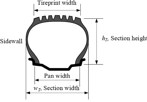
Figure 1.1 illustrates a cross section view of a tire on a rim to show the dimension parameters that are used to standard tires.
Pan width
wT, Section width
hT, Section height
Tireprint width
Sidewall
FIGURE 1.1. Cross section of a tire on a rim to show tire height and width.
The section height, tire height, or simply height, hT, is a number that must be added to the rim radius to make the wheel radius. The section width, ortire width, wT, is the widest dimension of a tire when the tire is not loaded.
1
Tire and Rim Fundamentals
We introduce and review some topics about tires, wheels, roads, vehicles, and their interactions. These subjects are needed to understand vehicle dynamics better.
1.1 Tires and Sidewall Information
Pneumatic tires are the only means to transfer forces between the road and the vehicle. Tires are required to produce the forces necessary to control the vehicle, and hence, they are an important component of a vehicle.
Figure 1.1 illustrates a cross section view of a tire on a rim to show the dimension parameters that are used to standard tires.
Pan width
wT, Section width
hT, Section height
Tireprint width
Sidewall
FIGURE 1.1. Cross section of a tire on a rim to show tire height and width.
The section height, tire height, or simply height, hT, is a number that must be added to the rim radius to make the wheel radius. The section width, ortire width, wT, is the widest dimension of a tire when the tire is not loaded.
R
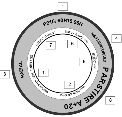
FIGURE 1.2. Side view of a tire and the most important information printed on a tire sidewall.
The codes in Figure 1.2 are:
1 Size number.
2 Maximum allowed inflation pressure.
3 Type of tire construction.
4 M&S denotes a tire for mud and snow.
5 E-Mark is the Europe type approval mark and number.
6 US Department of Transport (DOT) identification numbers.
7 Country of manufacture.
8 Manufacturers, brand name, or commercial name.
The most important information on the sidewall of a tire is the size number, indicated by 1 . To see the format of the size number, an example is shown in Figure 1.3 and their definitions are explained as follows.
P Tire type. Thefirst letter indicates the proper type of car that the tire is made for. P stands for passenger car. Thefirst letter can also be
ST for special trailer, T for temporary, and LT for light truck.
Passenger car
Tire width [mm]
Aspect ratio [%]
Radial
Rim diameter [in]
Load rating
Speed rating
P
215
60
R
15
96
H
P 215 / 60 R 15 96 H
FIGURE 1.3. A sample of a tire size number and its meaning.
60 Aspect ratio. This two-number code is the ratio of the tire section height to tire width, expressed as a percentage. Aspect ratio is shown by
sT.
sT =
hT
wT
×100 (1.1)
Generally speaking, tire aspect ratios range from 35, for race car tires, to
75for tires used on utility vehicles.
R Tire construction type.The letter R indicates that the tire has a radial construction. It may also be B for bias belt or bias ply, and
D for diagonal.
15 Rim diameter. This is a number in [in] to indicate diameter of the rim that the tire is designed tofit on.
96 Load rate or load index. Many tires come with a service description at the end of the tire size. The service description is made of a two-digit number (load index) and a letter (speed rating). The load index is a rep-resentation of the maximum load each tire is designed to support.
Table 1.1shows some of the most common load indices and their load-carrying capacities. The load index is generally valid for speeds under
210 km/h (≈130 mi/h).
H Speed rate. Speed rate indicates the maximum speed that the tire can sustain for a ten minute endurance without breaking down.
Table1.2shows the most common speed rate indices and their meanings.
Example 1 Weight of a car and load index of its tire.
Table1.1- Maximum load-carrying capacity tire index. Index Maximum load Index Maximum load
0 45 kg≈99 lbf
· · · 100 800 kg≈1764 lbf
71 345 kg≈761 lbf 101 825 kg≈1819 lbf
72 355 kg≈783 lbf 102 850 kg≈1874 lbf
73 365 kg≈805 lbf 103 875 kg≈1929 lbf
74 375 kg≈827 lbf 104 900 kg≈1984 lbf
75 387 kg≈853 lbf 105 925 kg≈2039 lbf
76 400 kg≈882 lbf 106 950 kg≈2094 lbf
77 412 kg≈908 lbf 107 975 kg≈2149 lbf
78 425 kg≈937 lbf 108 1000 kg≈2205 lbf
79 437 kg≈963 lbf 109 1030 kg≈2271 lbf
80 450 kg≈992 lbf 110 1060 kg≈2337 lbf
81 462 kg≈1019 lbf 111 1090 kg≈2403 lbf
82 475 kg≈1047 lbf 113 1120 kg≈2469 lbf
83 487 kg≈1074 lbf 113 1150 kg≈2581 lbf
84 500 kg≈1102 lbf 114 1180 kg≈2601 lbf
85 515 kg≈1135 lbf 115 1215 kg≈2679 lbf
86 530 kg≈1163 lbf 116 1250 kg≈2806 lbf
87 545 kg≈1201 lbf 117 1285 kg≈2833 lbf
88 560 kg≈1235 lbf 118 1320 kg≈2910 lbf
89 580 kg≈1279 lbf 119 1360 kg≈3074 lbf
90 600 kg≈1323 lbf 120 1400 kg≈3086 lbf
91 615 kg≈1356 lbf 121 1450 kg≈3197 lbf
92 630 kg≈1389 lbf 122 1500 kg≈3368 lbf
93 650 kg≈1433 lbf 123 1550 kg≈3417 lbf
94 670 kg≈1477 lbf 124 1600 kg≈3527 lbf
95 690 kg≈1521 lbf 125 1650 kg≈3690 lbf
96 710 kg≈1565 lbf 126 1700 kg≈3748 lbf
97 730 kg≈1609 lbf 127 1750 kg≈3858 lbf
98 750 kg≈1653 lbf 128 1800 kg≈3968 lbf
99 775 kg≈1709 lbf · · · ·
199 13600 kg≈30000 lbf
Example 2 Height of a tire based on tire numbers.
A tire has the size numberP215/60R15 96H. The aspect ratio60means the height of the tire is equal to 60%of the tire width. To calculate the tire height in [ mm], we should multiply the first number (215) by the second number(60)and divide by100.
hT = 215× 60
100 = 129 mm (1.2)
Table1.2- Maximum speed tire index.
Index Maximum speed Index Maximum speed
B 50 km/h≈31 mi/h P 150 km/h≈93 mi/h
C 60 km/h≈37 mi/h Q 160 km/h≈100 mi/h
D 65 km/h≈40 mi/h R 170 km/h≈106 mi/h
E 70 km/h≈43 mi/h S 180 km/h≈112 mi/h
F 80 km/h≈50 mi/h T 190 km/h≈118 mi/h
G 90 km/h≈56 mi/h U 200 km/h≈124 mi/h
J 100 km/h≈62 mi/h H 210 km/h≈130 mi/h
K 110 km/h≈68 mi/h V 240 km/h≈150 mi/h
L 120 km/h≈75 mi/h W 270 km/h≈168 mi/h
M 130 km/h≈81 mi/h Y 300 km/h≈188 mi/h
N 140 km/h≈87 mi/h Z +240 km/h≈+149 mi/h
Example 3 Alternative tire size indication.
If the load index is not indicated on the tire, then a tire with a size number such as255/50R17 100V may also be numbered by255/50V R17.
Example 4 Tire and rim widths.
The dimensions of a tire are dependent on the rim on which it is mounted. For tires with an aspect ratio of 50 and above, the rim width is approxi-mately70%of the tire’s width, rounded to the nearest0.5 in. As an example, aP255/50R16tire has a design width of255 mm = 10.04 inhowever,70%
of10.04 inis7.028 in, which rounded to the nearest0.5 in, is7 in. Therefore, aP255/50R16tire should be mounted on a 7×16rim.
For tires with aspect ratio45and below, the rim width is85%of the tire’s section width, rounded to the nearest 0.5 in. For example, a P255/45R17
tire with a section width of255 mm = 10.04 in, needs an 8.5 in rim because
85% of 10.04 in is 8.534 in ≈8.5 in. Therefore, a P255/45R17 tire should be mounted on an 81
2×17rim.
Example 5 Calculating tire diameter and radius.
We are able to calculate the overall diameter of a tire using the tire size numbers. By multiplying the tire width and the aspect ratio, we get the tire height. As an example, we use tire numberP235/75R15.
hT = 235×75%
= 176.25 mm≈6.94 in (1.3)
tire’s unloaded diameterD= 2R and radiusR.
D = 2×6.94 + 15
= 28.88 in≈733.8 mm (1.4)
R = D/2 = 366.9 mm (1.5)
Example 6 Speed rating code.
Two similar tires are coded as P235/70HR15 and P235/70R15 100H. Both tires have code H ≡210 km/h for speed rating. However, the second tire can sustain the coded speed only when it is loaded less than the specified load index, so it states 100H ≡800 kg 210 km/h.
Speed ratings generally depend on the type of tire. Offroad vehicles usu-ally use Q-rated tires, passenger cars usually use R-rated tires for typical street cars or T-rated for performance cars.
Example 7 Tire weight.
The average weight of a tire for passenger cars is10−12 kg. The weight of a tire for light trucks is14−16 kg, and the average weight of commercial truck tires is135−180 kg.
Example 8 Effects of aspect ratio.
A higher aspect ratio provides a softer ride and an increase in deflection under the load of the vehicle. However, lower aspect ratio tires are normally used for higher performance vehicles. They have a wider road contact area and a faster response. This results in less deflection under load, causing a rougher ride to the vehicle.
Changing to a tire with a different aspect ratio will result in a different contact area, therefore changing the load capacity of the tire.
Example 9 F BMW tire size code.
BMW, a European car, uses the metric system for sizing its tires. As an example, T D230/55ZR390 is a metric tire size code.T D indicates the BMW TD model,230is the section width in[ mm],55is the aspect ratio in percent,Z is the speed rating,Rmeans radial, and390 is the rim diameter in[ mm].
Example 10 F"M S," "M+S," "M/S," and "M&S" signs.
The sign "M S,"and "M+S," and "M/S," and "M&S" indicate that the tire has some mud and snow capability. Most radial tires have one of these signs.
Example 11 FU.S. DOT tire identification number.
The US tire identification number is in the format "DOTDN ZE ABCD
The next two characters,ZE, are a letter-number combination that refers to the specific mold used for forming the tire. It is an internal factory code and is not usually a useful code for customers.
The last four numbers, 1309, represents the week and year the tire was built. The other numbers, ABCD, are marketing codes used by the man-ufacturer or at the manman-ufacturer’s instruction. An example is shown in Figure 1.4.
DOT DNZE ABCD 1309
FIGURE 1.4. An example of a US DOT tire identification number.
DN is the plant code for Goodyear-Dunlop Tire located in Wittlich, Ger-many. ZE is the tire’s mold size, ABCD is the compound structure code,
13indicates the13thweek of the year, and09 indicates year2009. So, the tire is manufactured in the 13thweek of 2009at Goodyear-Dunlop Tire in Wittlich, Germany.
Example 12 FCanadian tires identification number.
In Canada, all tires should have an identification number on the sidewall. An example is shown in Figure 1.5.
DOT B3CD E52X 2112
FIGURE 1.5. An example of a Canadian DOT tire identification number.
This identification number provides the manufacturer, time, and place that the tire was made. The first two characters following DOT indicate the manufacturer and plant code. In this case,B3indicates Group Michelin located at Bridgewater, Nova Scotia, Canada. The third and fourth charac-ters,CD, are the tire’s mold size code. The fifth, sixth, seventh, and eighth characters,E52X, are optional and are used by the manufacturer. Thefinal four numbers, 2112, indicates the manufacturing date. For example,2112
indicate the twenty first week of year 2012. Finally, the maple leaf sign or the flag sign following the identification number indicates that the tire is manufactured in Canada. It also certifies that the tire meets Transport Canada requirements.
Example 13 FE-Mark and international codes.
regulation.ECEorU N ECE stands for the united nations economic com-mission for Europe. The number in the circle or rectangle is the country code. Example: 11 is the U K. The first two digits outside the circle or rectangle indicate the regulation series under which the tire was approved. Example: "02" is for ECE regulation 30 governing passenger tires, and "00" is forECEregulation54governing commercial vehicle tires. The re-maining numbers represent the ECE mark type approval numbers. Tires may have also been tested and met the required noise limits. These tires may have a secondECE branding followed by an "−s" for sound.
Table1.3indicates the European country codes for tire manufacturing. Besides theDOT andECE codes for US and Europe, we may also see the other country codes such as:ISO−9001for international standards or-ganization, C.C.C for China compulsory product certification,JIS D4230
for Japanese industrial standard.
Table1.3- European county codes for tire manufacturing. Code Country Code Country
E1 Germany E14 Switzerland
E2 France E15 Norway
E3 Italy E16 Finland
E4 Netherlands E17 Denmark
E5 Sweden E18 Romania
E6 Belgium E19 Poland
E7 Hungary E20 Portugal
E8 Czech Republic E21 Russia
E9 Spain E22 Greece
E10 Yugoslavia E23 Ireland
E11 United Kingdom E24 Croatia
E12 Austria E25 Slovenia
E13 Luxembourg E26 Slovakia
Example 14 FLight truck tires.
The tire sizes for a light truck may be shown in two formats:
LT245/70R16
or
32×11.50R16LT
In the first format, LT ≡light truck, 245 ≡tire width in millimeters,
70≡aspect ratio in percent,R≡radial structure, and 16≡rim diameter in inches.
Example 15 FU T QG ratings.
Tire manufacturers may put some other symbols, numbers, and letters on their tires supposedly rating their products for wear, wet traction, and heat resistance. These characters are referred to as U T QG(Uniform Tire Quality Grading), although there is no uniformity and standard in how they appear. There is an index for wear to show the average wearing life time in mileage. The higher the wear number, the longer the tire lifetime. An index of100is equivalent to approximately20000miles or30000 km. Other numbers are indicated in Table1.4.
Table1.4- Tread wear rating index. Index Life (Approximate)
100 32000 km 20000 mi
150 48000 km 30000 mi
200 64000 km 40000 mi
250 80000 km 50000 mi
300 96000 km 60000 mi
400 129000 km 80000 mi
500 161000 km 100000 mi
The U T QG also rates tires for wet traction and heat resistance. These are rated in letters between "A" to "C," where "A" is the best, "B" is intermediate and "C" is acceptable. An "A" wet traction rating is typically an indication that the tire has a deep open tread pattern with lots of sipping, which are thefine lines in the tread blocks.
An "A" heat resistance rating indicates two things: First, low rolling re-sistance due to stiffer tread belts, stiffer sidewalls, or harder compounds; second, thinner sidewalls, more stable blocks in the tread pattern. Temper-ature rating is also indicated by a letter between "A" to "CM," where "A" is the best, "B" is intermediate, and "C" is acceptable.
There might also be a traction rating to indicate how well a tire grips the road surface. This is an overall rating for both dry and wet conditions. Tires are rated as: "AA" for the best, "A" for better, "B" for good, and "C" for acceptable.
Example 16 FTire sidewall additional marks.
T L≡Tubeless
T T ≡Tube type, tire with an inner-tube
Made in Country≡Name of the manufacturing country
C≡Commercial tires made for commercial trucks; Example:185R14C B≡Bias ply
SF I ≡Side facing inwards
SF O≡Side facing outwards
T W I ≡Tire wear index
205/65 R15
205 mm 225 mm 245 mm
225/55 R16 245/45 R17
15 in 16 in 17 in
FIGURE 1.6. The plus one(+1)concept is a rule tofind the tire to a rim with a1inch increase in diameter.
SL≡Standard load; Tire for normal usage and loads
XL≡Extra load; Tire for heavy loads
rf ≡Reinforced tires
Arrow≡Direction of rotation
Some tread patterns are designed to perform better when driven in a specific direction. Such tires will have an arrow showing which way the tire should rotate when the vehicle is moving forwards.
Example 17 FPlus one (+1)concept.
The plus one(+1)concept describes the sizing up of a rim and matching it to a proper tire. Generally speaking, each time we add 1 in to the rim diameter, we should add 20 mm to the tire width and subtract 10% from the aspect ratio. This compensates the increases in rim width and diameter, and provides the same overall tire radius. Figure 1.6 illustrates the idea.
By using a tire with a shorter sidewall, we get a quicker steering response and better lateral stability. However, we will have a stiffer ride.
Example 18 FUnder- and over-inflated tire.
Overheat caused by improper inflation of tires is a common tire failure. An under-inflated tire will support less of the vehicle weight with the air pressure in the tire; therefore, more of the vehicle weight will be supported by the tire. This tire load increase causes the tire to have a larger tireprint that creates more friction and more heat.
Cap/Base tread
Belt buffer Sidewall
Bead bundle Body plies/Carcass
Inner liner
Inner layer
FIGURE 1.7. Illustration of a sample radial tire interior components and arrange-ment.
the road surface.
In a properly-inflated tire, approximately 95% of the vehicle weight is supported by the air pressure in the tire and 5% is supported by the tire wall.
1.2 Tire Components
A tire is an advanced engineering product made of rubber and a series of synthetic materials cooked together. Fiber, textile, and steel cords are some of the components that go into the tire’s inner liner, body plies, bead bundle, belts, sidewalls, and tread. Figure 1.7 illustrates a sample of tire interior components and their arrangement.
The main components of a tire are explained below.
Bead or bead bundle is a loop of high strength steel cable coated with rubber. It gives the tire the strength it needs to stay seated on the wheel rim and to transfer the tire forces to the rim.
Inner layers are made up of different fabrics, called plies. The most common ply fabric is polyester cord. The top layers are also called cap plies. Cap plies are polyesteric fabric that help hold everything in place. Cap plies are not found on all tires; they are mostly used on tires with higher speed ratings to help all the components stay in place at high speeds.
Belts or belt buffers are one or more rubber-coated layers of steel, poly-ester, nylon, Kevlar or other materials running circumferentially around the tire under the tread. They are designed to reinforce body plies to hold the treadflat on the road and make the best contact with the road. Belts reduce squirm to improve tread wear and resist damage from impacts and penetration.
The carcass or body plies are the main part in supporting the tension forces generated by tire air pressure. The carcass is made of rubber-coated steel or other high strength cords tied to bead bundles. The cords in a radial tire, as shown in Figure 1.7, run perpendicular to the tread. The plies are coated with rubber to help them bond with the other components and to seal in the air.
A tire’s strength is often described by the number of carcass plies. Most car tires have two carcass plies. By comparison, large commercial jetliners often have tires with30or more carcass plies.
The sidewall provides lateral stability for the tire, protects the body plies, and helps to keep the air from escaping from the tire. It may contain additional components to help increase the lateral stability.
Thetread is the portion of the tire that comes in contact with the road. Tread designs vary widely depending on the specific purpose of the tire. The tread is made from a mixture of different kinds of natural and synthetic rubbers. The outer perimeter of a tire is also called thecrown.
Thetread groove is the space or area between two tread rows or blocks. The tread groove gives the tire traction and is especially useful during rain or snow.
Example 19 Tire rubber main material.
There are two major ingredients in a rubber compound: the rubber and the filler. They are combined in such a way to achieve different objectives. The objective may be performance optimization, traction maximization, or better rolling resistance. The most common fillers are different types of carbon black and silica. The other tire ingredients are antioxidants, antiozonant, and anti-aging agents.
Tires are combined with several components and cooked with a heat treat-ment. The components must be formed, combined, assembled, and cured to-gether. Tire quality depends on the ability to blend all of the separate com-ponents into a cohesive product that satisfies the driver’s needs. A modern tire is a mixture of steel, fabric, and rubber. Generally speaking, the weight percentage of the components of a tire are:
1−Reinforcements: steel, rayon, nylon,16% 2−Rubber: natural/synthetic,38%
3−Compounds: carbon, silica, chalk, 30% 4−Softener: oil, resin, 10%
Example 20 Tire cords.
Because tires have to carry heavy loads, steel and fabric cords are used in their construction to reinforce the rubber compound and provide strength. The most common materials suitable for the tire application are cotton, rayon, polyester, steel,fiberglass, and aramid.
Example 21 Bead components and preparation.
The bead component of tires is a non-extensible composite loop that an-chors the carcass and locks the tire into the rim. The tire bead components include the steel wire loop and apex or bead filler. The bead wire loop is made from a steel wire covered by rubber and wound around the tire with several continuous loops. The bead filler is made from a very hard rubber compound, which is extruded to form a wedge.
Example 22 Tire ply construction.
The number of plies and cords indicates the number of layers of rubber-coated fabric or steel cords in the tire. In general, the greater the number of plies, the more weight a tire can support. Tire manufacturers also indicate the number and type of cords used in the tire.
Example 23 FTire tread extrusion.
Tire tread, or the portion of the tire that comes in contact with the road, consists of the tread, tread shoulder, and tread base. Since there are at least three different rubber compounds used in forming the tread profile, three rubber compounds are extruded simultaneously into a shared extruder head.
Example 24 FDifferent rubber types used in tires.
There are five major rubbers used in tire production: natural rubber, styrene-butadiene rubber (SBR), polybutadiene rubber (BR), butyl rubber, and halogenated butyl rubber. The first three are primarily used for tread and sidewall compounds, while butyl rubber and halogenated butyl rubber are primarily used for the inner liner and the inside portion that holds the compressed air inside the tire.
Example 25 FHistory of rubber.
About 2500 years ago, people living in Central and South America used the sap and latex of a local tree to waterproof their shoes, and clothes. This material was introduced to the first pilgrim travelers in the 17th century. The first application of this new material was discovered by the English as an eraser. This application supports the namerubber, because it was used for rubbing out pencil marks. The rubber pneumatic tires were invented in
1845and its production began in 1888.
C H
H H
C C
H C H
H C
H
H
FIGURE 1.8. Illustration of the monomer unit of natural rubber.
C H
H H
C C
H C H
H C
H
H
C
H H H
C C
H C H
H C
H
H S
S
FIGURE 1.9. Illustration of a vulcanized rubber.
Example 26 FA world without rubber.
Rubber is the main material used to make a tire compliant. A compliant tire can stick to the road surface while it goes out of shape and provides distortion to move in another direction. The elastic characteristic of a tire allows the tire to be pointed in a direction different than the direction the car is pointed. There is no way for a vehicle to turn without rubber tires, unless it moves at a very low speed. If vehicles were equipped with only noncompliant wheels then trains moving on railroads would be the main travelling vehicles. People could not live too far from the railways and there would not be much use for bicycles and motorcycles.
1.3 Radial and Non-Radial Tires
Cap/Base tread
Belt buffer Sidewall
Bead bundle Body plies/Carcass
Inner liner
Inner layer
FIGURE 1.10. Examples of a non-radial tire’s interior components and arrange-ment.
construction has its own set of characteristics that are the key to its per-formance.
The radial tire is constructed with reinforcing steel cable belts that are assembled in parallel and run side to side, from one bead to another bead at an angle of90 degto the circumferential centerline of the tire. This makes the tire moreflexible radially, which reduces rolling resistance and improves cornering capability. Figure 1.7 shows the interior structure and the carcass arrangement of a radial tire.
The non-radial tires are also calledbias-ply andcross-ply tires. The plies are layered diagonal from one bead to the other bead at about a 30 deg
angle, although any other angles may also be applied. One ply is set on a bias in one direction as succeeding plies are set alternately in opposing directions as they cross each other. The ends of the plies are wrapped around the bead wires, anchoring them to the rim of the wheel. Figure 1.10 shows the interior structure and the carcass arrangement of a non-radial tire.
The most important difference in the dynamics of radial and non-radial tires is their different ground sticking behavior when a lateral force is ap-plied on the wheel. This behavior is shown in Figure 1.11. The radial tire, shown in Figure 1.11(a), flexes mostly in the sidewall and keeps the tread
flat on the road. The bias-ply tire, shown in Figure 1.11(b) has less contact with the road as both tread and sidewalls distort under a lateral load.
(a) Radial tire (b) Non-Radial tire
FIGURE 1.11. Ground-sticking behavior of radial and non-radial tires in the presence of a lateral force.
of the vehicle. So, more vertical deflection is achieved with radial tires. As the sidewall flexes under the load, the belts hold the tread firmly and evenly on the ground and reduces tread scrub. In a cornering maneuver, the independent action of the tread and sidewalls keeps the tread flat on the road. This allows the tire to hold its path. Radial tires are the preferred tire in most applications today.
The cross arrangement of carcass in bias-ply tires allows it act as a unit. When the sidewalls deflect or bend under load, the tread squeezes in and distorts. This distortion affects the tireprint and decrease traction. Because of the bias-ply inherent construction, sidewall strength is less than that of a radial tire’s construction and cornering is less effective.
Example 27 Increasing the strength of tires.
The strength of bias-ply tires increases by increasing the number of plies and bead wires. However, more plies means more mass, which increases heat and reduces tire life. To increase a radial tire’s strength, larger diameter steel cables are used in the tire’s carcass.
Example 28 Tubeless and tube-type tire construction.
A tubeless tire is similar in construction to a tube-type tire, except that a thin layer of air and moisture-resistant rubber is used on the inside of the tubeless tire from bead to bead to obtain an internal seal of the casing. This eliminates the need for a tube andflap. Both tires, in equivalent sizes, can carry the same load at the same inflation pressure.
Example 29 FNew shallow tires.
Low aspect ratio tires are radial tubeless tires that have a section width wider than their section height. The aspect ratio of these tires is between
Example 30 FTire function.
A tire is a pneumatic system to support a vehicle’s load. Tires support a vehicle’s load by using compressed air to create tension in the carcass plies. Tire carcass are a series of cords that have a high tension strength, and almost no compression strength. So, it is the air pressure that creates tension in the carcass and carries the load. In an inflated and unloaded tire, the cords pull equally on the bead wire all around the tire. When the tire is loaded, the tension in the cords between the rim and the ground is relieved while the tension in other cords is unchanged. Therefore, the cords opposite the ground pull the bead upwards. This is how pressure is transmitted from the ground to the rim.
Besides vertical load carrying, a tire must transmit acceleration, braking, and cornering forces to the road. These forces are transmitted to the rim in a similar manner. Acceleration and braking forces also depend on the friction between the rim and the bead. A tire also acts as a spring between the rim and the road.
1.4 Tread
The tread pattern is made up of treadlugs and treadvoids. The lugs are the sections of rubber that make contact with the road and voids are the spaces that are located between the lugs. Lugs are also calledslotsorblocks, and voids are also called grooves. The tire tread pattern of block-groove configurations affect the tire’s traction and noise level. Wide and straight
grooves running circumferentially have a lower noise level and high lateral friction. More lateral grooves running from side to side increase traction and noise levels. A sample of a tire tread is shown in Figure 1.12.
Tires need both circumferential and lateral grooves. The water on the road is compressed into the grooves by the vehicle’s weight and is evacuated from the tireprint region, providing better traction at the tireprint contact. Without such grooves, the water would not be able to escape out to the sides of the wheel. This would causes a thin layer of water to remain between the road and the tire, which causes a loss of friction with the road surface. Therefore, the grooves in the tread provide an escape path for water.
On a dry road, the tire treads reduce grip because they reduce the contact area between the rubber and the road. This is the reason for using treadless or slick tires at smooth and dry race tracks.
Lugs
Voids
FIGURE 1.12. A sample of tire tread to show lugs and voids.
smaller voids cannot clean themselves easily and if the voids fill up with mud, the tire loses some of it’s traction. The all-terrain tire is good for highway driving.
Example 31 Asymmetrical and directional tread design.
The design of the tread pattern may be asymmetric and change from one side to the other. Asymmetric patterns are designed to have two or more different functions and provide a better overall performance.
A directional tire is designed to rotate in only one direction for maximum performance. Directional tread pattern is especially designed for driving on wet, snowy, or muddy roads. A non-directional tread pattern is designed to rotate in either direction without sacrificing in performance.
Example 32 Self-cleaning.
Self-cleaning is the ability of a tire’s tread pattern to release mud or material from the voids of tread. This ability provides good bite on every rotation of the tire. A better mud tire releases the mud or material easily from the tread voids.
1.5
F
Hydroplaning
ω
Tire
Water film
Ground plane
FIGURE 1.13. Illustration of hydroplaning phnomena.
Deep grooves running from the center front edge of the tireprint to the corners of the back edges, along with a wide central channel help water to escape from under the tire. Figure 1.13 illustrates the hydroplaning phenomena when the tire is riding over a water layer.
There are three types of hydroplaning: dynamic, viscous, and rubber hydroplaning.Dynamic hydroplaning occurs when standing water on a wet road is not displaced from under the tires fast enough to allow the tire to make pavement contact over the total tireprint. The tire rides on a wedge of water and loses its contact with the road. The speed at which hydroplaning happens is calledhydroplaning speed.
Viscous hydroplaning occurs when the wet road is covered with a layer of oil, grease, or dust. Viscous hydroplaning happens with less water depth and at a lower speed than dynamic hydroplaning.
Rubber hydroplaning is generated by superheated steam at high pressure in the tireprint, which is caused by the friction-generated heat in a hard braking.
Example 33 Aeronautic hydroplaning speed.
In aerospace engineering the hydroplaning speed is estimated in [knots]
by
vH = 9√p (1.6)
where,pis tire inflation pressure in[psi].
For main wheels of aB757aircraft, the hydroplaning speed would be
vH = 9 √
144
= 108knots≈55.5 m/s.
Equation (1.6) for a metric system would be
x
y a
b
Tireprint
FIGURE 1.14. A tireprint.
speed of a car using tires with pressure28psi≈193053 Pais
vx = 5.5753×10⁻² √
193053
≈ 24.5 m/s (1.8)
≈ 47.6knots≈88.2 km/h≈54.8 mi/h.
1.6 Tireprint
The contact area between a tire and the road is called thetireprint and is shown byAP. At any point of a tireprint, the normal and friction forces are transmitted between the road and tire. The effect of the contact forces can be described by a resulting force system including force and torque vectors applied at the center of the tireprint.
The tireprint is also calledcontact patch,contact region, ortire footprint. A simplified model of tireprint is shown in Figure 1.14.
The area of the tireprint is inversely proportional to the tire pressure. Lowering the tire pressure is a technique used for off-road vehicles in sandy, muddy, or snowy areas, and for drag racing. Decreasing the tire pressure causes the tire to slump so more of the tire is in contact with the surface, giving better traction in low friction conditions. It also helps the tire grip small obstacles as the tire conforms more to the shape of the obstacle, and makes contact with the object in more places. Low tire pressure increases fuel consumption, tire wear, and tire temperature.
Example 34 Uneven wear in front and rear tires.
Pan width Section height
Center line
Tread width Section width
Offset
Outside Inside
Rim
diam
eter
FIGURE 1.15. Illustration of a wheel and its dimensions.
Front tires, especially on front-wheel drive vehicles, wear out more quickly than rear tires.
1.7 Wheel and Rim
When a tire is installed on a rim and is inflated, it is called a wheel. Awheel is a combined tire andrim. The rim is the metallic cylindrical part where the tire is installed. Most passenger cars are equipped with steel rims. The steel rim is made by welding a disk to a shell. However, light alloy rims made with light metals such as aluminium and magnesium are also popular. Figure 1.15 illustrates a wheel and the most important dimensional names. A rim has two main parts:flangeandspider. Theflange orhubis the ring or shell on which the tire is mounted. The spider or center section is the disc section that is attached to the hub. The rim width is also called pan width and measured from inside to inside of the bead seats of the flange. Flange provides lateral support to the tire. A flange has two bead seats providing radial support to the tire. The well is the middle part between the bead seats with sufficient depth and width to enable the tire beads to be mounted and demounted on the rim. Therim hole orvalve aperture is the hole or slot in the rim that accommodates the valve for tire inflation.
Rim width Rim width
DC rim
WDCH rim
Hump WDC rim Rim diameter
Rim width
Rim diameter
Rim diameter
FIGURE 1.16. Illustration of DC, WDC, and WDCH rims and their geometry.
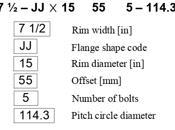
Rim width [in]
Flange shape code
Offset [mm]
Number of bolts
Pitch circle diameter
7 1/2
JJ
15
55
5
114.3
7 ½ – JJ 15 55 5 – 114.3
Rim diameter [in]
FIGURE 1.17. A sample rim number.
drop center rim (W DC). The W DC may also come with a hump. The humpedW DC may be calledW DCH. Their cross sections are illustrated in Figure 1.16.
Drop center (DC) rims usually are symmetric with a well between the bead seats. The well is built to make mounting and demounting the tire easy. The bead seats are around 5 deg tapered. Wide drop center rims (W DC) are wider thanDC rims and are built for low aspect ratio tires. The well of W DC rims are shallower and wider. Today, most passenger cars are equipped withW DCrims. TheW DCrims may be manufactured with a hump behind the bead seat area to prevent the bead from slipping down.
Rim
Spindle
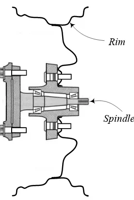
FIGURE 1.18. Illustration of a wheel attched to the spindle axle.
the distance between the inner plane and the center plane of the rim. A rim may be designed with a negative, zero, or positive offset. A rim has a positive offset if the spider is outward from the center plane.
Theflange shape code signifies the tire-side profile of the rim and can be
B,C,D,E,F,G,J,JJ,JK, andK. Usually the profile code follows the nominal rim width but different arrangements are also used. Figure 1.18 illustrates how a wheel is attached to the spindle axle.
Example 35 Wire spoke wheel.
A rim that uses wires to connect the center part to the exterior flange is called a wire spoke wheel, or simply a wire wheel. The wires are called spokes. This type of wheel is usually used on classic vehicles. The high-power cars do not use wire wheels because of safety. Figure 1.19 depicts two examples of wire spoke wheels.
Example 36 Light alloy rim material.
Metal is the main material for manufacturing, rims, however, new com-posite materials are also used for rims occasionally. Comcom-posite material rims are usually thermoplastic resin with glass fiber reinforcement, devel-oped mainly for low weight. Their strength and heat resistance still need improvement before being a proper substitute for metallic rims.
Other than steel and composite materials, light alloys such as aluminum, magnesium, and titanium are used for manufacturing rims.
recy-Center line Center line
FIGURE 1.19. Two samples of wire spoke wheel.
Ground plane Magnesium rim Aluminum rim Steel rim
FIGURE 1.20. The difference between aluminum, magnesium, and steel rims in regaining road contact after a jump.
cling. Magnesium is about30% lighter than aluminum, and is excellent for size stability and impact resistance. However, magnesium is more expensive and it is used mainly for luxury or racing cars. The corrosion resistance of magnesium is not as good as aluminum. Titanium is much stronger than aluminum with excellent corrosion resistance. However, titanium is expen-sive and hard to be machine processed.
The difference between aluminum, magnesium, and steel rims is illus-trated in Figure 1.20. Light weight wheels regain contact with the ground quicker than heavier wheels.
Example 37 Spare tire.
weight, cost, and gas mileage. Doughnut spare tires can not be driven far or fast.
Example 38 Wheel history.
Stone and wooden wheels were invented and used somewhere in the Mid-dle East about5000years ago. Hard wheels have some inefficient character-istics namely poor traction, low friction, harsh ride, and poor load carrying capacity.
Solid rubber tires and air tube tires began to be used in the late nineteen and early twentieth century.
1.8 Vehicle Classi
fi
cations
Road vehicles are usually classified based on their size and number of axles. Although there is no standard or universally accepted classification method, there are a few important and applied vehicle classifications.
1.8.1 ISO and FHWA Classification
ISO3833 classifies ground vehicles in7groups:1−Motorcycles
2−Passenger cars
3−Busses
4−Trucks
5−Agricultural tractors
6−Passenger cars with trailer
7−Truck trailer/semi trailer road trains
The Federal Highway Administration (FHWA) classifies road vehicles based on size and application. All road vehicles are classified in13classes as described below:
1−Motorcycles
2−Passenger cars, including cars with a one-axle or two-axle trailer
3−Other two-axle vehicles, including: pickups, and vans, with a one-axle or two-axle trailer
4−Buses
5−Two axle, six-tire single units
6−Three-axle single units
7−Four or more axle single units
8−Four or fewer axle single trailers
9−Five-axle single trailers
10−Six or more axle single trailers
12−Six-axle multi-trailers
13−Seven or more axle multi-trailers
Figure 1.21 illustrates the FHWA classification. The definition of FHWA classes follow.
Motorcycles: Any motorvehicle having a seat or saddle and no more than three wheels that touch the ground is a motorcycle. Motorcycles, motor scooters, mopeds, motor-powered or motor-assisted bicycles, and three-wheel motorcycles are in this class. Motorcycles are usually, but not necessarily, steered by handlebars. Figure 1.22 depicts a three-wheel mo-torcycle.
Passenger Cars: Street cars, including sedans, coupes, and station wag-ons manufactured primarily for carrying passengers, are in this class. Fig-ure 1.23 illustrates a two-door passenger car. Passenger cars are also called street cars,automobiles, orautos.
Other Two-Axle, Four-Tire Single-Unit Vehicles: All two-axle, four-tire vehicles other than passenger cars make up this class. This class includes pickups, panels, vans, campers, motor homes, ambulances, hearses, car-ryalls, and minibuses. Other two-axle, four-tire single-unit vehicles pulling recreational or light trailers are also included in this class. Distinguishing class 3from class 2 is not clear, so these two classes may sometimes be combined into class2.
Buses: A motor vehicle able to carry more than ten persons is a bus. Buses are manufactured as traditional passenger-carrying vehicles with two axles and six tires. However, buses with three or more axles are also man-ufactured.
Two-Axle, Six-Tire, Single-Unit Trucks: Vehicles on a single frame in-cluding trucks, camping and recreational vehicles, motor homes with two axles, and dual rear wheels are in this class.
Three-Axle Single-Unit Trucks: Vehicles having a single frame including trucks, camping, recreational vehicles, and motor homes with three axles are in this class.
Four-or-More-Axle-Single-Unit Trucks: All trucks on a single frame with four or more axles make up this class.
Four-or-Fewer-Axle Single-Trailer Trucks: Vehicles with four or fewer axles consisting of two units, one of which is a tractor or straight truck power unit, are in this class.
Five-Axle Single-Trailer Trucks: Five-axle vehicles consisting of two units, one of which is a tractor or straight truck power unit, are in this class.
Six-or-More-Axle Single-Trailer Trucks: Vehicles with six or more axles consisting of two units, one of which is a tractor or straight truck power unit, are in this class.
1
2
3
4
5
6
7
8
9
10
11
12
13
FIGURE 1.22. A three-wheel motorcycle.
FIGURE 1.23. A two-door passenger car.
Six-Axle Multi-Trailer Trucks: Six-axle vehicles consisting of three or more units, one of which is a tractor or straight truck power unit, are in this class.
Seven or More Axle Multi-Trailer Trucks: Vehicles with seven or more axles consisting of three or more units, one of which is a tractor or straight truck power unit are in this class.
The classes 6 to 13 are also called truck. A truck is a motor vehicle designed primarily for carrying load and/or property.
1.8.2 Passenger Car Classi
fi
cations
A passenger car or automobile is a motorvehicle designed for carrying ten or fewer persons. Automobiles may be classified based on their size and weight. Size classification is based on wheelbase, the distance between front and rear axles. Weight classification is based on curb weight, the weight of an automobile with standard equipment, and a full complement of fuel and other fluids, but with no load, persons, or property. The wheelbase is rounded to the nearest inch and the curb weight to the nearest 100 lb ≈ 50 kgbefore classification.
For a size classification, passenger car may be classified as asmall, mid-size, andlargecar.Small cars have a wheelbase of less than99 in≈2.5 m, midsize cars have a wheelbase of less than109 in≈2.8 mand greater than
Each class may also be divided further.
For a weight classification, passenger car may be classified aslight, mid-weight, andheavy.Light weight carshave a curb weight of less than2400 lb≈ 1100 kg, midweight cars have a curb weight of less than 3400 lb≈1550 kg
and more than 2500 lb ≈1150 kg, and heavy cars have a curb weight of more than3500 lb≈1600 kg. Each class may also be divided in some sub-divisions.
Dynamically, passenger cars may be classified by their type of suspension, engine, driveline arrangement, weight distribution, or any other parameters that affect the dynamics of a car. However, in the market, passenger cars are usually divided into the following classes according to the number of passengers and load capacity.
1−Economy
2−Compact
3−Intermediate
4−Standard Size
5−Full Size
6−Premium Luxury
7−Convertible Premium
8−Convertible
9−Minivan
10−Midsize
11−SUV
In another classification, cars are divided according to size and shape. However, using size and shape to classify passenger cars is not clear-cut; many vehicles fall in between classes. Also, not all are sold in all countries, and sometimes their names differ between countries. Common entries in the shape classification are thesedan,coupe,convertible,minivan/van,wagon, andSUV.
Asedan is a car with a four-door body configuration and a conventional trunk or a sloping back with a hinged rear cargo hatch that opens upward.
Acoupe is a two-door car.
Aconvertible is a car with a removable or retractable top.
A minivan/van is a vehicle with a box-shaped body enclosing a large cargo or passenger area. The identified gross weight of a van is less than
10 000 lb≈4 500 kg. Vans can be identifiable by their enclosed cargo or pas-senger area, short hood, and box shape. Vans can be divided intomini van, small van, midsize van, full-size van, and large van. The van subdivision has the same specifications as SUV subdivisions.
Awagonis a car with an extended body and a roofline that extends past the rear doors.
ground clearance. The SUV is also known as 4-by-4, 4W D, 4×4or 4x4. SUVs can be divided intomini,small,midsize,full-size, andlarge SUV.
Mini SUVs are those with a wheelbase of less than or equal to88 in ≈ 224 cm. A mini SUV is typically a microcar with a high clearance, and off-road capability. Small SUVs have a wheelbase of greater than 88 in ≈
224 cm with an overall width of less than 66 in ≈ 168 cm. Small SUVs are short and narrow 4×4multi-purpose vehicles. Midsize SUVs have a wheelbase of greater than 88 in ≈ 224 cm with an overall width greater than66 in≈168 cm, but less than75 in≈190 cm. Midsize SUVs are4×4
multi-purpose vehicles designed around a shortened pickup truck chassis. Full-size SUVs are made with a wheelbase greater than88 in≈224 cmand a width between75 in≈190 cmand80 in≈203 cm. Full-size SUVs are4×4
multi-purpose vehicles designed around an enlarged pickup truck chassis. Large SUVs are made with a wheelbase of greater than88 in≈224 cmand a width more than80 in≈203 cm.
Because of better performance, the vehicle manufacturing companies are going to make more cars four-wheel-drive. So, four-wheel-drive does not refer to a specific class of cars anymore.
Atruck is a vehicle with two or four doors and an exposed cargo box. A light truck has a gross weight of less than 10 000 lb≈4 500 kg. A medium truck has a gross weight from10 000 lb≈4 500 kgto26 000 lb≈12 000 kg. A heavy truck is a truck with a gross weight of more than 26 000 lb ≈
12 000 kg.
1.8.3 Passenger Car Body Styles
Passenger cars are manufactured in so many different styles and shapes. Not all of those classes are made today, and some have new shapes and still carry the same old names. Some of them are as follows:
Convertibleorcabrioletcars are automobiles with removable or retractable rooves. There are also the subdivisions cabrio coach or semi-convertible with partially retractable rooves.
Coupé or coupe are two-door automobiles with two or four seats and a
fixed roof. In cases where the rear seats are smaller than regular size, it is called a two-plus-two or2 + 2. Coupé cars may also be convertible.
Crossover SUV or XUV cars are smaller sport utility vehicles based on a car platform rather than truck chassis. Crossover cars are a mix of SUV, minivan, and wagon to encompass some of the advantages of each.
Estate car or just estate is the British/English term for what North Americans call a station wagon.
Hardtopcars are those having a removable solid roof on a convertible car. However, today a fixed-roof car whose doors have no fixed window frame are also called a hardtops.