Copyright © 2018 Authors. This is an open access article distributed under the Creative Commons Attribution License, which permits unrestricted use, distribution, and reproduction in any medium, provided the original work is properly cited.
International Journal of Engineering & Technology
Website: www.sciencepubco.com/index.php/IJET
Research paper
Underground Radio Propagation on Frequency Band 97 Mhz –
130 Mhz
S Suherman*, Ali Hanafiah Rambe, Agustiar Widodo Tanjung
Electrical Engineering Department, Universitas Sumatera Utara, Medan, Indonesia *Corresponding author E-mail: [email protected]
Abstract
Radio communications do not work only in the air and underwater, but also underground. Some applications such as mining and earth-quake detection require underground radio devices. This paper reports an assessment of underground radio characteristics for frequency band 97 MHz to 130 MHz. The assessments were performed through an experimental propagation measurement and a mathematical prediction. Both assessments then are compared by using the normalized graph to predict propagation characteristics so that correct link budget for future application can be assisted. The mathematic analysis and measurement results still produce huge errors; achieving 50.33% for frequency 130.762 MHz, 17.58% for 109.818 MHz and 13.38% for 97.335 MHz. Error can be minimized when the ground permittivity is more precise
Keywords: Underground radio propagation, Friis radio model, Correction factor
1.
Introduction
Underground radio propagation experiences dispersion by multi-layer ground, power absorption, and scattering [1], [2]. Complex structure of the ground exerts problem for radio signal o propagate. Deep attenuation occurs that degrade signal significantly. The working frequency should be examined carefully for particularly type of ground path so that the underground radio can work. A very high frequency is suitable for underground propagation as its signal can penetrate deep underground, and requires low trans-mitting power. This frequency has been used for mining worker [3], [4]. The VHF signal is good deliver electromagnetic power, but is sensitive to the ground characteristics. Therefore, in order to get maximum results, an assessment of the underground radio system should be performed in area where the radio is applied. In order to understand the underground radio characteristics, this paper describes an example of underground propagation meas-urement and mathematical modeling, where impact of ground parameters will be presented.
In order to understand the basic concept, the mathematical analy-sis of the underground signal propagation is outlined in the fol-lowing sub sections.
A. Underground signal propagation
Underground signal propagation experiences attenuation, multi-path spreading as each area passing though by the signal has dif-ferent ground parameters, fading and signal scattering. Beside signal propagates through the ground, some signals may pass through the air, reflect from the air to the ground and pass to the underground. This resuls two paths of radio signal, direct signal and refected signal. Direct signal is the main components, but reflected signal sometimes is significant. In order to avoid reflect-ed signal, transmitter antenna should be penetratreflect-ed in to the ground.
B. Multi-path fading
When direct signal is the only considered one, the complex struc-ture of the ground produce an ideal wave surface that causes verti-cal reflection and refraction. It is even worse if the plantation roots and mud with heterogenic characteristics presents in signal path. Then, multi-path fading occurs. Multi-path fading in the air is caused by random diffraction of the air. Underground fading be-haves similarly where amplitude and phase are time invariant random. The multi-path follows Rayleigh or log-normal distribu-tion probability.
C. Model for predicting underground propagation
Underground signal propagation requires approximation to model. The original losses calculated by using Friis equation. The re-ceived signal is the transmitted signal gained by the transmitter and receiver antennas, but decreases to path loss [5]:
Pr(dBm) = Pt(dBm) + Gr(dB) + Gt(dB) - L0(dB) (1)
This path loss can be formulized to as Equation 2, where losses increase to distance and frequency [5]:
L0(dB) = 32,4 + 20 log(d) + 20 log(f) (2)
Where d is distance between transmitter and receiver in km, f is the operating frequency in MHz. Correction factor should be added to Friis equation by considering the effect of the ground. The received power level is then determined by:
Pr = Pt + Gr + Gt – Lp (3)
The corrected path loss Lp is Lo + Ls, where Ls be the ground
propagation. Ls is calculated by considering propagation
differ-ence between air and ground. Some aspects to be considered:
1. Signal speed and wavelength
2. Amplitude
International Journal of Engineering & Technology 723
The path loss increment caused by ground propagation consists of space loss and attenuation loss caused by wavelength differences between air and ground:
Ls = Lα+Lβ (4)
Lα = 8,69αd (5)
Lβ = 154 – 20 log(f)(Hz) + 20log(β) (6)
The attenuation constant α (1/m) and phase shift β (radian/m) depends on dielectric parameter which is approximated using Pep-linski [5]:
Permeability is the characteristics reflecting how easy a material is affected by a magnetic material. This characteristic influence how signal propagate. Most ground permeability is assumed as free space: μ = µ0 and µ0 = 1 [6].
E. Regression Analysis
Regression analysis is declared as the correlation between two mathematical equations which means each variable relates to other variables. The regressions analysis is used in this paper to describe how close the experimental research and modeling.
2.
Research Method
In order to measure underground radio propagation characteristics on 97 MHz to 130 MHz, some equipment are employed. A bipo-lar junction transistor signal generator is assembled using circuit diagram shown in Figure 1 [7].
The tuned circuit consists of C1 and L1 is determined to generate sinusoidal signal from 97 MHz to 130 MHz. By voltage divider feeding the Q1, collector current flows through LC. The Q1 ampli-fies signal within range of the intended frequencies, so that collec-tor current falls to these frequencies. This signal is feed backed to basis through emitter, and amplified until at a stable level. Finally the desired frequency signal is fed to a wire antenna.
Fig.1: Signal generator
A rectifier with two-diodes supplies the voltage for the transmitter, providing 6 volt; 7.5 volt and 9 volt. The circuit is shown in Fig-ure 2. A spectrum analyzer is employed to receive the transmitted signal as shown in Figure 3.
Fig.2: VHF Signal generator and power supply
Fig.3: Vector network analyzer
Fig. 4: Measurement plan
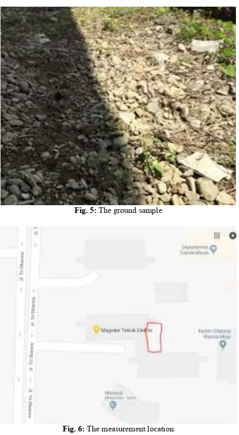
Ground appearance is shown in Figure 5 and location is in Medan city as plotted in the map in Figure 6.
Fig. 5: The ground sample
Fig. 6: The measurement location
Permittivity parameters are taken from [9] as described in Table 1 [9].
Table.1: Dielectric parameters
Type
Ground with mud and stone 6.53 1.88
3.
Measurement and Analysis Results
3.1 Measurement Results
By reading values displayed in receiver, the received signal strength for various distances can be plotted. Figure 7 plotted sig-nal strength received for transmitting frequencies of 130.762 MHz, 109.818 MHz, and 97.335 MHz. These sample frequencies are representing frequencies on band 97 – 130 MHz.
a. Frequency of 130.762 MHz
b. Frequency of 109.818 MHz
c. Frequency of 97.335 MHz
Fig.7: Measurement results
3.2 Modelling Results
International Journal of Engineering & Technology 725
a. Frequency of 130.762 MHz
b. Frequency of 109.818 MHz
c. Frequency of 97.335 MHz
Fig. 8: Modelling results
3.3 Normalized Analysis
In order to get more precise compaison, normalized analysis is performed. Figure 9 shows the normalized comparison. In average, error acheves more than 50% for frequency 130 MHz. Frequency 109.818 MHz gets 17.58% error and 97.335 MHz has 13.38%.
a. Frequency of 130.762 MHz
b. Frequency of 109.818 MHz
c. Frequency of 97.335 MHz
Fig. 9: Modelling results
Fig. 10: Error changes as Ɛ’ changes
4.
Conclusion
This paper has examined underground radio propagation by means of measurement and mathematical analysis. Experiment was con-ducted from frequency 97 MHz to 130 MHz. The results show that ground attenuates radio signal. The mathematical model employed to predict signal level experience high errors. The highest is 50.33% for frequency 130.762 MHz, decreasing as frequency lowers: 17.58% for 109.818 MHz and 13.38% for 97.335 MHz.
High errors may be caused the non-precise equipment or in accu-rate ground parameters. It is shown that by changing one ground parameter, error decreases. Better propagation model may be re-quired to obtain better prediction.
Acknowledgement
This research was funded by DIKTI under schema of Penelitian Dasar Ungglan Perguruan Tinggi 2018.
References
[1] M. C. Akyildiz, I. F., Sun, Z., & Vuran, “Signal propagation techniques for wireless underground communication networks,” Phys. Commun., vol. 2, no. 3, p. 167–183., 2009.
[2] S. Suherman, “WiFi-Friendly Building to Enable WiFi Signal Indoor,” Bull. Electr. Eng. Informatics, vol. 7, no. 2, 2018. [3] I. F. Vuran, M. C., & Akyildiz, “Channel model and analysis for
wireless underground sensor networks in soil medium,” Phys. Commun., vol. 3, no. 4, p. 245–254., 2010.
[4] D. Subramaniam et al., “A Stacked Planar Antenna with Switchable Small Grid Pixel Structure for Directive High Beam Steering Broadside Radiation,” Int. J. Eng. Technol., vol. 7, no. 2.5, pp. 122–127, Mar. 2018.
[5] Z. S. and M. C. V. Ian F.Akyildiz, Signal propagation techniques for wireless underground communication networks. United States: Elsevier., 2009.
[6] S. Takahashi, K., Igel, J., Preetz, H., & Kuroda, “Basics and application of ground-penetrating radar as a tool for monitoring irrigation process,” Probl. Perspect. challenges Agric. water Manag., 2012.
[7] G. Mietzner, J., Nickel, P., Meusling, A., Loos, P., & Bauch, “Responsive communications jamming against radio-controlled improvised explosive devices,” IEEE Commun. Mag., vol. 50, no. 10, p. 38–46., 2012.
[8] A. H. R. and R. F. A IM Dunia, Suherman, “Measuring the power consumption of social media applications on a mobile device,” J. Phys. Conf. Ser., vol. 978, no. 1, p. 012104, 2018.