Prosiding Konferensi Nasional Engineering Hotel III, Universitas Udayana, Bali, 6-7 Juli 2012
233Mechanical design of vertical pressure vessel for air receiver using software
Cokorda Prapti Mahandari and Dani Kurniawan
Mechanical Engineering Department, Faculty of Industrial Technology, Gunadarma University, Jakarta-Indonesia E-mail: [email protected]
Abstract
There are many applications of pressure vessels in industry. A vertical pressure vessel as an air receiver had been designed implementing graphical based software. Input parameters for mechanical design of this vessel were provided by one of pressure vessel manufacturer as the following: volume, diameter, design pressure, material type for each element of pressure vessel and corrosion allowance. Analyses were conducted on the component of pressure vessel mainly: head, shell, nozzle, manhole and leg. The result presents thickness of head, thickness of shell, thickness of nozzle for drain and manhole, and axial compression on the leg. Inspection on extreme fiber elongation on head and shell had been also carried out. In addition determination for the requirement of Post Weld Heating Treatment (PWHT) had been also discussed. The results present partially as they were generated except for PWHT checked that presents on table.
Key words: air receiver, pressure vessel, design, PWHT
1. Background
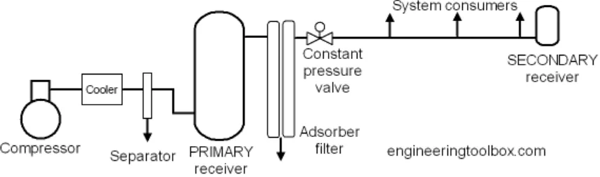
An air receiver is very important for compressed air system to storage the compressed air. The main function of air receiver is to equalize the pressure variation for the start and stop and modulate sequence of the compressor or it can be as a pulsation damper. Compressor should not run continuously and air receiver store and deliver air pressure when the compressor is not running. Moreover by storage the compressed air, it maintains the pressure to be constant from volume variation of the consumption and demand of the system. In addition air receiver can collect condensate and water contained in the air after compressor or can serve as a moisture trap.
Two different kind of air receiver are primary receiver which is located close to the compressor and secondary receiver which is near the system consumers as it is illustrated on Figure 1[1].
Figure 1. Primary and secondary air receiver.
Prosiding KNEP III 2012 – ISBN 978-602-9042-92-4 234
software for designing the structure of vertical pressure vessel for particular air receiver. It is in full compliance with ASME section VIII [3]. Analysis would be run on head, shell, nozzle manhole and leg. Moreover determination of the need for PWHT would also be investigated.Study on this similar topic has been done on pressure vessel for three phase separator [3]. Nevertheless the pressure vessel was horizontal and analysis was done on elements of pressure vessel including the saddle without PWHT checked.
2. Research Method
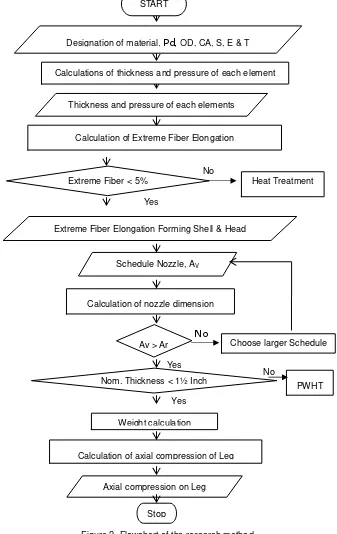
Air receiver specification was obtained from the pressure vessel manufacturer. Design parameter would be the input parameters which were as the following: volume of pressure vessel, shell diameter, design pressure, design temperature and maximum corrosion allowance. Design procedure and equations follows ASME Code Section VIII. Since the equations involved will appear on the result of analysis, they are not presented in this section. Analysis was conducted based on flowchart that is shown on Figure 2.
Figure 2. Flowchart of the research method.
Material type for each elements, design pressure, design temperature, shell diameter, and corrosion Yes
No
No Calculation of Extreme Fiber Elongation
Extreme Fiber < 5%
Calculation of nozzle dimension
Heat Treatment
Yes
Stop Schedule Nozzle, AV
Av > Ar Choose larger Schedule
Weight calculation
Calculation of axial compression of Leg
Axial compression on Leg
Calculations of thickness and pressure of each element
Thickness and pressure of each elements START
Yes
Nom. Thickness < 1½ Inch
PWHT No
Designation of material, Pd, OD, CA, S, E & T
Prosiding Konferensi Nasional Engineering Hotel III, Universitas Udayana, Bali, 6-7 Juli 2012
235 allowance had already determined by the industry that ordered the air receiver. These parameters would be submitted to the input screen that showed in the same screen whenever the drawing element was sketch. Analysis was started on each element then on the pressure vessel. The output of analysis can be presented in many features. It can be in the form of table, or export to word processor in the form of final report. Since this research have not completed yet, the output would be presented as they are generated. Even though the result for complete PWHT checked is presented on a table.3. Result and discussion
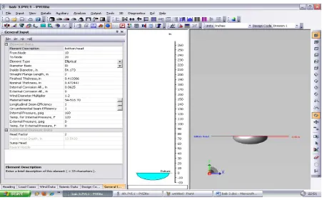
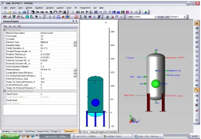
Analysis of the pressure vessel element was started with drawing and setting the input parameter on head as it is shown on Figure 3.
Figure 3. Ellipsoidal bottom head of vessel and input data screen.
The result of analysis is presented partly as they were generated just as the following:
Thickness Due to Internal Pressure [Tr]:
= (P x (D+2 x CA) x K) / (2 x S x E-0.2 x P) Appendix 1-4(c)
= (160.000 x (54.1730 + 2 x 0.0625) x 1.00) /( 2 x 20000.00 x 1.00-0.2 x160.000) = 0.2174 + 0.0625 = 0.2799 in
Max. All. Working Pressure at Given Thickness [MAWP]:
= (2 x S x E x (T-Ca))/(K x(D + 2 x Ca) + 0.2 x (T-Ca)) per Appendix 1-4 (c) = (2x20000.00x1.00x(0.3509))/(1.00x(54.1730+2x0.0625)+0.2x(0.3509)) = 258.155 psig
Maximum Allowable Pressure, New and Cold [MAPNC]:
= (2 x Sa x E x T)/(K x D + 0.2x T ) per Appendix 1-4 (c) = (2 x 20000.00 x 1.00 x 0.4134)/(1.00 x 54.1730 + 0.2 x 0.4134)
= 304.769 psig
Actual stress at given pressure and thickness [Sact]: = (P x (K x (D + 2 x CA) + 0.2 x (T-CA)))/(2 x E x (T-CA))
= (160.000 x (1.00 x (54.1730 + 2 x 0.0625) + 0.2 x (0.3509)))/(2 x 1.00 x (0.3509))
= 12395.634 psi.
Required Thickness of Straight Flange = 0.281 in
Prosiding KNEP III 2012 – ISBN 978-602-9042-92-4 236
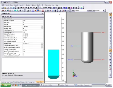
Figure 4. Cylindrical shell of vessel and input data screen.Analysis on shell was also conducted by drawing and inputting parameters just as it is shown on Figure 4. The results are presented partly in the following:
According to the order specification of the air receiver, unit design must be in British System Unit. However changing the unit is very simple because it is provided in the software. Not only the unit system but also the design codes are offered.
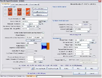
There are 8 nozzles on the air receiver and one of nozzle calculation is presented and the input data screen for nozzle drain is shown on Figure 5.
Thickness Due to Internal Pressure [Tr]:
= (P x (D/2 + Ca))/(S x E-0.6 x P) per UG-27 (c)(1)
= (160.000 x (54.1730/2 + 0.0625))/(20000.00 x 1.00-0.6 x 160.000) = 0.2182 + 0.0625 = 0.2807 in
Max. All. Working Pressure at Given Thickness [MAWP]: = (S x Ex(T-Ca))/((D/2 + Ca) + 0.6 x (T-Ca)) per UG-27 (c)(1) = (20000.00 x 1.00 x (0.3509))/((54.1730/2 + 0.0625)+0.6 x 0.3509) = 256.500 psig
Maximum Allowable Pressure, New and Cold [MAPNC]: = (SA x E x T)/(D/2+0.6 x T) per UG-27 (c)(1)
= (20000.00 x 1.00 x 0.4134)/(54.1730/2 + 0.6 x 0.4134) = 302.464 psig
Actual stress at given pressure and thickness [Sact]: = (P x ((D/2+CA)+0.6 x (T-CA)))/(Ex(T-CA))
= (160.000 x ((54.1730/2 + 0.0625) + 0.6 x (0.3509)))/(1.00 x (0.3509)) = 12475.634 psi
Prosiding Konferensi Nasional Engineering Hotel III, Universitas Udayana, Bali, 6-7 Juli 2012
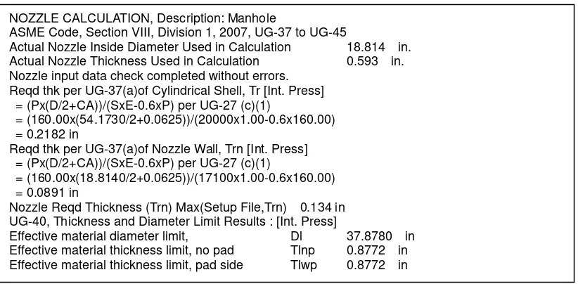
237 Figure 5. Nozzle input and analysisThere is a manhole on the shell of air receiver and it is considered as a nozzle. Manhole is necessary for repair work or inspection and clean out the air receiver. Manhole sizing design includes not only outside diameter or dimension but also thickness of its wall and the distance or leg between pipe openings [4]. Input data for analyzing manhole is almost similar to Figure 5 and then the result partially is presented.
Complete analysis of nozzles and manhole should discuss other parameters such as area, weld leg, weld size calculation, stress reduction factor, reinforcement thickness, reinforcement area, etc [5, 6, and 7]. These parameters appeared on the generated results however in this paper they are presented partially. Leg or support analysis presented also partially results. It presented axial compression on leg only. Others parameter such as bolting size requirement for leg, torsional buckling stress, bolting size requirement for leg base plate, moment at base plate, base plate lifting moment, base plate require thickness, etc.
PWHT checked for the whole elements of pressure vessel are listed on Table 1. It concluded that this pressure vessel did not need PWHT as all element thicknesses are less than the thickness limit for PWHT. Then the result of total weight calculations is demonstrated. The inclusive pressure vessel for air receiver is presented on Figure 7 and leg analyses are exhibited subsequently.
NOZZLE CALCULATION, Description: Drain
ASME Code, Section VIII, Division 1, 2007, UG-37 to UG-45 Actual Nozzle Inside Diameter Used in Calculation 0.815 in. Actual Nozzle Thickness Used in Calculation 0.250 in. Nozzle input data check completed without errors.
Reqd thk per UG-37(a)of Elliptical Head, Tr [Int. Press] = (Px(Kx(D+2xCA)))/(2xSxE-0.2xP) per UG-37(a)(3)
= (160.00x(0.90x(54.1730+2x0.0625)))/(2 x20000x1.00-0.2x160.00) = 0.1956 in
Reqd thk per UG-37(a)of Nozzle Wall, Trn [Int. Press] = (Px(D/2+CA))/(SxE-0.6xP) per UG-27 (c)(1)
= (160.00x(0.8150/2+0.0625))/(17100x1.00-0.6x160.00) = 0.0044 in
Prosiding KNEP III 2012 – ISBN 978-602-9042-92-4 238
ASME Code, Section VIII, Division 1, 2007, UG-37 to UG-45
Actual Nozzle Inside Diameter Used in Calculation 18.814 in.
Nozzle Reqd Thickness (Trn) Max(Setup File,Trn) 0.134 in UG-40, Thickness and Diameter Limit Results : [Int. Press]
Prosiding Konferensi Nasional Engineering Hotel III, Universitas Udayana, Bali, 6-7 Juli 2012
239 Figure 6. Vertical air receiver.RESULTS FOR LEGS : HydroTest Case Description: LEGS Legs attached to: bottom head
Section Properties : Single Angle L6X6X0.6250 USA AISC 1989 Steel Table
Leg Length from Attachment to Base Leglen 58.189 in Distance Leg Up Side of Vessel 8.000 in Number of Legs Nleg 4 Cross Sectional Area for L6X6X0.6250 Aleg 7.110 in² Section Inertia ( strong axis ) 24.200 in4 Section Inertia ( weak axis ) 24.200 in4 Section Modulus ( strong axis ) 5.660 in ³ Section Modulus ( weak axis ) 5.660 in ³ Radius of Gyration ( strong axis ) 1.840 in Radius of Gyration ( weak axis ) 1.840 in Leg Orientation - Strong Axis
Overturning Moment at top of Legs 8529.5 in-lb Total Weight Load at top of Legs W 17228.2 lbf Total Shear force at top of Legs 157.0 lbf Additional force in Leg due to Bracing Fadd 0.0 lbf Occasional Load Factor Occfac 1.333 Effective Leg End Condition Factor k 1.000 Note: The Legs are Not Cross Braced
The Leg Shear Force includes Wind and Seismic Effects Maximum Shear at top of one Leg [Vleg]:
= ( Max(Wind, Seismic) + Fadd ) x ( Imax / Itot ) = ( 157.0 + 0.0 ) x ( 24.1 / 96.29 )
= 39.24 lbf
Axial Compression, Leg futhest from N.A. [Sma] = ((W/Nleg)+(Mleg/(NlegmxRn)))/Aleg)
= ((17228 / 4 ) + (102353 /( 2 x 31.75 )))/ 7.110 ) = 624.66 psi
Axial Compression, Leg closest to N.A. [Sva] = ( W / Nleg ) / Aleg
Prosiding KNEP III 2012 – ISBN 978-602-9042-92-4 240
4. ConclusionMechanical design of a vertical pressure vessel for air receiver has been accomplished incorporating graphical-based software. Analysis has been carried out on the elements of pressure vessel and the result can be presented rapidly.
Further research need to explore environmental parameter such as earthquake, thermal load, fluctuation load and so on. Moreover dynamic processes in design need to employ for optimization instead of fixing the input parameter.
References
[1] Compressed Air Receiver, [http://www.engineeringtoolbox.com/compressed-air-receivers-d_846.html] (Accessed 25 May 2012)
[2] ASME Boiler & Pressure Vessel Code: Rules for Construction of Pressure vessels, (ASME VIII), Division 1, 2007
[3] Cokorda Prapti Mahandari and Miko Sandi, Mechanical Design of Pressure Vessel for Three Phase Separator Using PV Elite Software, Proceeding of Seminar Nasional Energi Terbaharukan dan Produksi Bersih, Bandar Lampung, 2012
[4] Moss, Dennis. Pressure Vessel Design Manual. Third Edition, Gulf Professional Publishing Inc, Burlington, 2004.
[5] Megyesy, Eugene F., Pressure Vessel Handbook. Eleventh Edition, Pressure Vessel Publishing Inc. Tulsa., Oklahoma.2001.
[6] R. Farr, James. And H. Jawad, Maan, Guide Book for the Design of ASME Section VIII Pressure Vessel,
ASME Press, New York, 2001.