SECOND GENERATION MOSAIC:A NOVEL MECHANISM BASED ON REFERENCE
DATABASE FOR MAP UPDATING
HuGaoxiang*a,Frank Bignoneb
a
EADS-CHINA;b Astrium geo-information services
KEYWORDS: Map Updating, Mosaic, Parallel Processing, Orthoimage Mosaic
ABSTRACT:
A totally new automatic workflow mechanism, named Second generation Mosaic module, based on the well-known Pixel Factory
system, will be introduced here, which enables existing digital orthoimages and mosaics to be quickly updated. The process extracts
all required parameters from the reference database to be able to perform automatic bundle adjustment and radiometric adaptation.In
this paper, two examples for both satellite data and aerial data processed based on this mechanism will be presented here and
discussed. Finally, the cost reduction will also be analysed according to the real mapping updating project.In a final statement, this
paper will present an integrated solution named second generation mosaic module based on the well-known Pixel Factory system
which is completely dedicated to fast processing of photogrammetric products Thanks to this integrated hardware and software
solution, it is even possible to manage large data volume quickly in order to have precise map updating information as soon as
possible after acquisition.
1. SECOND GENERATION MOSAIC CONCEPT AND
PRINCIPLE
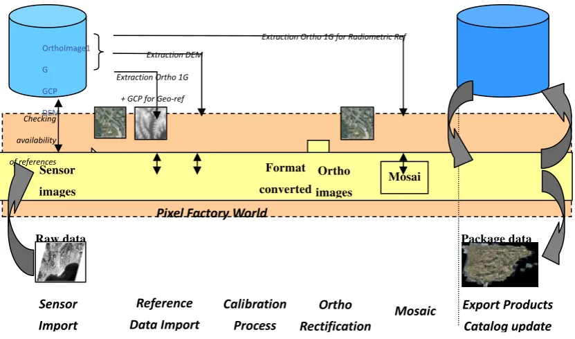
SGM (Second Generation Mosaic) is a global process that
allows generating rectified imagery automatically by using
available referenced imagery as a source for georeferencing,
rectifying and dodging the new imagery. The principle is to use
the referenced imagery to create a pattern of quasi-GCPs that
will be matched between the new imagery and the referenced
imagery. This should allow adjusting the new imagery without
any additional GCPs. It combines three different tools in a
single package:
- A database management tool;
- A workflow management tool;
- Integrated activities that allow the automatic processing
of data: automatic bundle adjustment, Bundle Quality
Check.
The database management tool allows to maintain a repository
The database management tool allows to maintain a repository
of imagery (ground orthos and elevation images), GCPs and to
manage queries. Imagery will be extracted (and filtered)
according to the project area and user specifications. Once the
new imagery is imported, the Automatic Bundle Adjustment
activity will:
- create and match tie points between the new images;
- create and match tie points between the new images and
the georeferenced image (or use existing GCPs); adjust
the block and filter again tie points using user defined
specifications.
The Bu1ndle Quality Check activity is a stop/go point in the workflow. When the residuals exceed a user defined threshold,
the process will halt and the user should take corrective action.
If the residuals are under the threshold, the Validate Bundle
Adjustment activity will be executed and the rectification
sequence will start.[1][2].
Figure 1. Second Mosaic Generation (SGM) principle
2. REFERENCE DATABASE CHARACTERISTICS
There is no need to convert the project data to the geographic
WGS84 coordinates systems, or to actually run a project in that
system either. This footprint is an additional tag that is used to
speed up the identification of relevant data. The reference
database used by SGM is a repository of three types of data:
- ortho images
- GCP
- elevation images (DEM)
There are very few restrictions about the data itself. All
cartographic systems are virtually supported. Elevation data
should be in raster format. The reference database stores the
characteristics of the data and a link to each image. Therefore,
the imagery must be stored on an accessible file system. In
order to extract relevant data, the footprint of each data is also
stored in geographic / WGS84 coordinates.
Extracting data from the database is done by using the Get
Reference from a reference database. This activity will:
- check that there is data available;
- filter the data according to various user defined
criteria (such as the source of data, its accuracy etc.);
• check that the resulting set of data covers the
requested AOI;
- extract the data, resample and convert it into the
project coordinate system.
While it is possible to have different ortho images overlapping
each other and use all of them for the bundle adjustment,
elevation data will be merged and resampled to form a single
elevation image.
3. GENERATING GCPS
Ground control point might be of two types: quasi-GCP and
true GCP. In SGM, a GCP comprises a set of coordinates, an
accuracy value and an image tile. The tile is extracted from the
ortho image used as reference. When measuring or adjusting,
no distinction is made between the points. The only difference
might be the accuracy value attached to the coordinates.
Quasi-GCP are points that are created according to a user
defined pattern. These tie points are matched between the
reference images and the new imagery. The planimetric
coordinates are interpolated in the reference ortho image, and
Sensor
Export
Products
Catalog
update
Pixel
Factory
World
FormatRaw data Package data
Checking availability of references
Extraction Ortho 1G for Radiometric Ref
Extraction DEM
the elevation is interpolated from the DEM. After the matching,
the accuracy attached to the coordinate will be the accuracy of
the reference data.
True GCP are points that have been previously measured in the
field, or have been selected by an operator from a reliable data
source (e.g. high resolution ortho image, map etc.). An image
tile from a reference image must be manually attached to those
points beforehand, so that they can be matched accurately on
the new image.
4. AUTOMATIC WORKFLOW ENGINE
This workflow allows creating the customized workflow, and
all the photogrammetric process activities can be
interconnected using the graphical easy to use workflow editor.
It can help fully automatic photogrammetric process, and even
a push mode embed the whole module will help the satellite
receiving station for automatic product updating.
The workflow comprises three groups of activities:
- Preparation: importing new imagery; extracting data from
the database;
- Bundle adjustment: setting up the project, creating tie
points, optimizing parameters, validating the results
- Rectifying the new imagery: creating a DSM/DTM if
necessary, creating ortho images, mosaicking and
balancing. In most cases, you might use an existing or
predefined workflow and assign new settings. Otherwise
it is suggested that you duplicate and modify an existing
one
A workflow consists in launching automatically pre-defined
tasks. The workflow engine accepts:
- Parameter binding
- Parallels steps processing
- Conditionals branches for correction
5. USE CASE
In this paper, two examples for both satellite data and aerial
data processed based on this mechanism will be presented here
and discussed. Finally, the cost reduction will also be analysed
according to the real mapping updating project.
5.1 Aerial dataset usecase
5.1.1 Dataset: The provided dataset consists of:
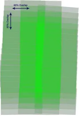
90 Level3 RGB UCD images (around 80% and 80% overlap
between images).
- Exterior orientation data in orima format (from other software).
- Camera Calibration data.
- Reference data from RefereceDB
¾
DEM,DSM¾
TrueOrtho¾
Color Reference ortho images.Figure 2. The outline of the provided data
5.1.2 Automatic workflow settings: Basically, in workflow
definition editor, four steps are needed:
1. Create a new workflow definition or import an
existed one.
2. Select the activities that could be used in your
workflow definition
3. Draw the graphic workflow
4. Make links between related activities, andspecific
necessary constraint.
Hereafter is the complete workflow set in workflow editor for
Figure 3. The footprint of UCD images
5.1.3 Bundle Adjustment based on reference data: For the
bundle adjustment, as the reference ortho images and elevation
data are extracted from database, all tie points are matched
between the reference images and the new imagery. The
planimetric coordinates are interpolated in the reference ortho
image, and the elevation is interpolated from the DSM. After
the matching, the accuracy attached to the coordinate will be
the accuracy of the reference data. The bundle adjustment was
then realized by using those automatic tie-points, and by
optimizing the exterior orientation (X,Y,Z,omega,phi and
kappa) for each image.[3]
Also, an automatic filtering technique was applied in order to
remove blunders gradually until the accuracy can be achieved.
Control points coordinates residuals(unit:meter)
XYZ bias -0.00045 0.00009 -0.001695
XYZ std 0.08331 0.04779 0.091288
XYZ max 0.16227 0.0669 0.150933
Xy residuals unit:pixel
xy bias -0.000011 0.000008
xy std 0.166236 0.179751
Xy max 0.901190 0.944950
Table 1. Accuracy of the UCD project
Figure 4. Tiepoints of UCD project
5.1.4 Digital Surface Model: The Digital Surface Model was
computed by merging all individual Digital Surface Models
computed from all reasonable stereoscopic pairs of input aerial
images. After this fusion task, automatic filtering is applied in
order to remove remaining blunders in the computed DSM.
The next figure displays the filtered DSM (no values are
outlined in red) and the corresponding interpolated DSM
(shaded display).
Figure 5. DSM automatically extracted from initial aerial
The quality of this DSM is correct, nevertheless height
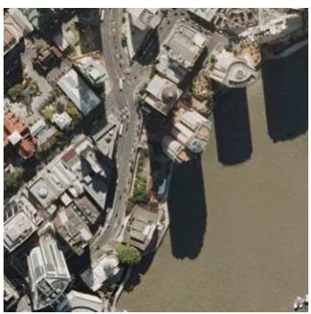
.1.5 GroundOrtho Mosaic: The ground orthoimage mosaic
igital aerial images after bundle
- rectification,
urban areas.
he first step of the processing is to compute individual image
- areas in order to avoid cut-lines crossing
Figure 6. Mosaic with overlaid cut-line (each color is a
fter cut-line computation, the complete mosaic is computed
Mosaic generation,
ualization between images,
ence
- lines.
ll those steps are done in the same time, thus allowing faster
age radiometric difference at the same time globally based
Figure 7. Computed GroundOrthoimage (left: cutline, right:
Figure 8. part of Mosaic
2 Satellite data usecase
SGM also has a potential use for map updating from satellite restitution inside the dense CBD (Center Business Distric) is
impaired with the lack of overlap across track (60% in the
processed dataset instead of 80%). The overlap along track is
too much and 70% will have been enough.
5
was processed by using:
- Initial RGB d
adjustment,
DTM for image
- DSM for cut-line generation in
- Reference ortho for color balance
T
rectification. Then based on those images, the DTM / DSM,
SGM can automatically compute a cut-line that will optimize:
- Radiometric changes between neighbouring images,
- Angle of view in order to privilege most nadir point
of view,
Occlusion
occluded areas in images.
- Local radiometric eq
- Global radiometric equalization based on refer
ortho images,
Fuzzy margin along
cut-A
computation. The radiometric equalization permits to optimize im
on the radiometric information (contrast and luminance) from
reference ortho imagesand locally (dodging of image
difference).
images as similar to the workflow as Aerial dataset. Amosaic
processing based on mixed satellite dataset,4 scenes
SPOT5(XS1 XS2 XS3) and 2 scenes ASTER(vrni1 ) is taken.
Figure 9. Inputdataset (Left:Spot5,Middle:ASTER,Left:Spot+ASTER)
he whole workflow desgined from data input to the final output is drawn below: T
ImportSpot
InitialBundleAdjus tment
GetReferenceFromDB(TrueOrtho,DSM)
AutoBundleAdjustment ManageBundleAdj
ustment
BundleQuaility Check
SubSetAutBundle Adjustment
VisualBundleAdju
stmentResidual OptimizeParameter
ValidateBundle Adjustment
MosaicOrtho (XS2 Virn2) AutoMosaCutline
RectifySensorImage (SPOT5)
Data Input Bundle Adjustment
Preparation
Reference Data Extraction
Automatic Bundle Adjustment
Ground Ortho &Mosaic computing
ImportAster
MosaicOrtho (XS1 virn1)
MosaicOrtho (XS3 virn3b) RectifySensorImage
(ASTER) SPOT5+ASTER SGM Mosaic WorkFlow
Figure 10. Workflow of the SPOT+ASTER SGM Mosaic
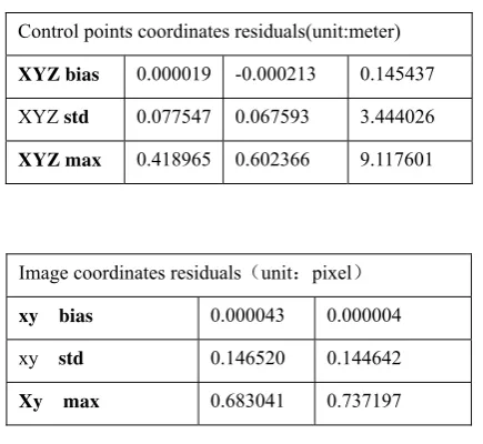
ere is the multi-sensor bundle adjustment result:
Control points coordinates residuals(unit:meter) H
XYZ bias 0.000019 -0.000213 0.145437
XYZ std 0.077547 0.067593 3.444026
XYZ max 0.418965 0.602366 9.117601
Image coordinates residuals unit:pixel
xy bias 0.000043 0.000004
xy std 0.146520 0.144642
Xy max 0.683041 0.737197
Table 2. Adjustment result of the UCD project
hanks to the unique seamless automated image mosaicking
result
ASTER
(Vnir3n vnir2 vnir1)
Aster Image
Spot Image
SPOT5(XS1 XS2 XS3)
Mosaic Cutline Mosaic
Mosaic Result T
techniques, though the color difference between ASTER and
6. CONCLUSION
The proposed methodology provides an efficient way for any
kinds of data/map updating. The Second Generation Mosaic
(SGM) Add-on module is a cost-effective new module for Pixel
Factorywhich enables existing digital orthoimages and mosaics
to be quickly updated. The process extracts all required
parameters from the reference database to be able to perform
automatic bundle adjustment and radiometric adaptation. The
time to produce a new mosaic is spectacularly reduced and a
perfect fit between new and existing data is obtained. The
Add-on can be used for both satellite and aerial imagery for
every kind of production environment (including the Ground
receiving station).And cost reduction in producing SGM
imagery results from eliminating 4 main activities:
- Ground survey with GPS capture,
- Geometric/Aerial Triangulation,
- DEM acquisition and processing,
- Radiometric and atmospheric correction.
Cost reduction by drastically reducing sidelap and overlap of a
flight if stereo pairs are not desired. Finally, it is between 20%
and 80% less expensive than “first generation” mosaics. This
new method of production addresses budget constraints and
you preserve your original investment. Previously-completed
mapping with all its features will be updated by the new
second-generation imagery.
REFERENCES
[1]
Manuel Jauregui, A procedure for map updating using
digital momo-plotting and DTMs,IAPRS,Vol.32,Part
4"GIS-Between Vision and Applications",Stuttgart,1998
[2]
Ma Li,Physical barrier detection for updating of
navigation databases from high resolution satellite
imagery,ISPRS Workshop on Updating Geo-spatial
Databases with Imagery & The 5th ISPRS Workshop on
DMGISs
[3]
Frank Bignone. Processing of stereo-scanner: from stereo
plotter to Pixel Factory. Photogrammetric Week, Stuttgart,
2003