KELOMPOK 2
KELOMPOK 2
Darma
Darma Adhi
Adhi W.
W.
(11210009)
(11210009)
Galuh
Galuh Intan
Intan P.
P.
(11210012)
(11210012)
Bhatara
Bhatara Putra
Putra M.
M.
(11210014)
(11210014)
Mulyani
(11210020)
Mulyani
(11210020)
Muliyani
(11210023)
Muliyani
(11210023)
Ali
Ali Akbar
Akbar
(11210024)
(11210024)
Tia
Tia Utari
Utari
(11210028)
(11210028)
Eko
Bhatara Putra Mediriyanto
Bhatara Putra Mediriyanto
Konsep Dasar
Konsep Dasar
Apa itu Bearing?
Apa itu Bearing?
Tipe beban pada bearing
Tipe beban pada bearing
1. Bantalan radial
1. Bantalan radial (Journal Bearing) (Journal Bearing)
Arah beban yang di tumpu bantalan ini Arah beban yang di tumpu bantalan ini adalah tegak lurus dengan sumbu poros adalah tegak lurus dengan sumbu poros
2. Bantalan aksial
2. Bantalan aksial (Thrust Bearing) (Thrust Bearing)
Arah beban bantalan ini adalah sejajar Arah beban bantalan ini adalah sejajar
dengan sumbu poros dengan sumbu poros
3. Bantalan kombinasi
3. Bantalan kombinasi (combination bearing) (combination bearing)
Bantalan ini menumpu beban yang Bantalan ini menumpu beban yang arahnya sejajar dan tegak lurus dengan arahnya sejajar dan tegak lurus dengan sumbu poros
Introduction
Introduction
•• Journal bearing termasuk salahsatu sliding Journal bearing termasuk salahsatu sliding bearing dan keterbalikkanbearing dan keterbalikkan
dari ball bearing dari ball bearing
•• Journal bearing secara umum digunakan pada mesin Journal bearing secara umum digunakan pada mesin piston kendaraanpiston kendaraan
bermotor berbahan bakar bensin atau diesel bermotor berbahan bakar bensin atau diesel
•• Kelebihan :Kelebihan :
•• Bearing type ini mampu menopang shaft yang berat.Bearing type ini mampu menopang shaft yang berat. •• Awet dan tahan lama Awet dan tahan lama
•• Efek redaman dari film minyak membantu membuat mesinEfek redaman dari film minyak membantu membuat mesin
beroperasi dengan tenang dan halus. beroperasi dengan tenang dan halus.
•• Kekurangan :Kekurangan :
•• Membutuhkan suplai minyak pelumas yang besarMembutuhkan suplai minyak pelumas yang besar
•• Hanya cocok untuk temperatur dan kecepatan rendahHanya cocok untuk temperatur dan kecepatan rendah •• Pembentukan lapisan minyak pelumas lambatPembentukan lapisan minyak pelumas lambat
Bearing Diagram
Bearing Diagram
Journal bearing
Journal bearing – – Berfungsi sebagai bantalan poros engkol yang berputar Berfungsi sebagai bantalan poros engkol yang berputar
Oil inlet
Oil inlet – – T Tempat masuknya minyak empat masuknya minyak pelumaspelumas
Ketika oli pelumas masuk ke dalam bearing, oli akan memenuhi Ketika oli pelumas masuk ke dalam bearing, oli akan memenuhi clearance/ gap antara shaft dan bearing sehinggga mengakibatkan clearance/ gap antara shaft dan bearing sehinggga mengakibatkan tekanan fuida meningkat dan daya angkat hidrodinamis terhadap shaft tekanan fuida meningkat dan daya angkat hidrodinamis terhadap shaft
Type
Type Typical Typical Loading Loading ApplicationApplication
(
(aa)) PPaarrttiiaal al arrcc Unidirectional Unidirectional load load Shaft Shaft guides, guides, dampersdampers
(
(aa)) CCiirrccuum fm feerreennttiiaall
groove, Axial groove
groove, Axial groove
types
types
Variable
Variable load load direction direction Internal Internal combustion combustion enginesengines
(
(aa)) CCyylliinnddrriiccaall Medium to heavyMedium to heavy Unidirectional load Unidirectional load
General machinery General machinery
(
(aa)) PPrreessssuurre e ddaamm Light Light loads, loads, unidirectional unidirectional High High speed speed turbines, turbines, compressorcompressor
(
(aa)) OOvveerrsshhoott Light Light loads, loads, unidirectional unidirectional Steam Steam turbinesturbines
(
(aa)) MMuullttiilloobbee Light Light loads, loads, unidirectional unidirectional Gearing, Gearing, compressorcompressor
(
(aa)) PPrreellooaaddeedd Light Light loads, loads, unidirectional unidirectional Minimize Minimize vibrationvibration
(
Movement of the bearing
Movement of the bearing
Video
Video
Infinitely Long Approximation (ILA)
Infinitely Long Approximation (ILA)
Menentukan jari-jari shaft dan
ILA
ILA
MenentukBoun
8.3 BOUNDARY CONDITIONS
8.3 BOUNDARY CONDITIONS
Assumsi :
Assumsi :
ṔṔ
= 0
= 0
θ θ= 0
= 0
Ṕ Ṕ −
−
Dimana :
Dimana :
Ps = tekanan suplai
Ps = tekanan suplai
C
C =
= radial
radial clearence
clearence
R
R =
= radius
radius bearing
bearing
=
= viskos
viskositas
itas pelumas
pelumas
= kecepatan
= kecepatan
putaran poros
putaran poros
8.4 FULL SOMMERFELD BOUNDARY
8.4 FULL SOMMERFELD BOUNDARY
CONDITIONS
CONDITIONS
Asumsi :
Asumsi :
ṔṔ
= 0
= 0
θθ
= 2
= 2
ππ(360)
(360)
cos
cos +θ
11 ++ ɛ ɛ θθ
+θ
Substitusi Sommerfeld :
Substitusi Sommerfeld :
8.4 FULL SOMMERFELD BOUNDARY
8.4 FULL SOMMERFELD BOUNDARY
CONDITIONS
CONDITIONS
Tekanan puncak terjadi ketika
Tekanan puncak terjadi ketika
cos
cos
−3
(2+
(2+
−3
))
Dimana :
Dimana :
cos
cos
=
= sudut
sudut angular
angular pada
pada
tekanan maksimum
tekanan maksimum
=
= rasio
rasio eksentrisita
eksentrisitass
= =
= eksentrisitas
= eksentrisitas
C
Dari persamaan 8.9 asumsi P = 0 pada
Dari persamaan 8.9 asumsi P = 0 pada
Ɵ π
Ɵ π
,,besarnya tekanan
besarnya tekanan
puncak tak berdimensi adalah :
puncak tak berdimensi adalah :
8.4 FULL SOMMERFELD BOUNDARY
8.4 FULL SOMMERFELD BOUNDARY
CONDITIONS
CONDITIONS
Ṕ Ṕ 3(4−
3(4−
2(1−
2(1−
)(4−5
)(4−5
))
(2+
(2+
++
))
))
.
.
−3
−3
22 ++
Yang terjadi pada :
Yang terjadi pada :
Besarnya tekanan puncak tak berdimensi pada distribusi tekanan
Besarnya tekanan puncak tak berdimensi pada distribusi tekanan
adalah :
adalah :
Load Carrying Based
Load Carrying Based
on Full
Load Carrying Based
Load Carrying Based
on Full
on Full
Sommerfe
Sommerfe
ld Condition
ld Condition
ѾѾ
Arah Radial
Arah Radial
Ѿ
Ѿ
Arah
Arah Tangensia
Tangensiall
(8.10)
(8.10)
(8.11)
(8.11)
Dari
Dari substitusi
substitusi tekanan
tekanan tak
tak berdimensi
berdimensi pada
pada persamaan
persamaan 8.9
8.9 dengan
dengan
persamaan 8.10 dan 8.11 maka
persamaan 8.10 dan 8.11 maka didapatkan :
didapatkan :
0
0
Ѿ
Ѿ
12
12
(1−
Load Carrying Based
Load Carrying Based
on Full
on Full
Sommerfe
Sommerfe
ld Condition
ld Condition
Dimana Beban tak berdimensi:
Dimana Beban tak berdimensi:
(8.13)
(8.13)
Resultan dari
Resultan dari
Ѿ
Ѿ
dan
dan
Ѿ
Ѿ
(8.14)
(8.14)
ѾѾ
Dengan
Dengan
= beban yang diproyeksikan
= beban yang diproyeksikan
Ns = kecepatan poros dalam rev/s
Ns = kecepatan poros dalam rev/s
Ѿ Ѿ
Ѿ Ѿ
++Ѿ
Ѿ
(
Load Carrying Based
Load Carrying Based
on Full
on Full
Sommerfe
Sommerfe
ld Condition
ld Condition
Attitude Angle
Attitude Angle
(8.15)
(8.15)
ɸɸ −Ѿ
−Ѿ
Ѿ
Ѿ ∞∞
ɸɸ
..
Dalam berbagai kasus, jika
Dalam berbagai kasus, jika
Ɛ
Ɛ
= 0
= 0
ѾѾ
0
0
Ɛ8.5
8.5
DEFINITION OF THE
DEFINITION OF THE
SOMMERFELD NUMBER
SOMMERFELD NUMBER
Bilangan Sommerfeld (S) merupakan bilangan tak berdimensi yang
Bilangan Sommerfeld (S) merupakan bilangan tak berdimensi yang
merupakan
merupakan
parameter
parameter karakterisasi
karakterisasi
performansi
performansi
sebuah
sebuah bearing.
bearing.
Bilangan ini menunjukkan karakteristik gesekan total dari bantalan.
Bilangan ini menunjukkan karakteristik gesekan total dari bantalan.
8.5
8.5
DEFINITION OF THE
DEFINITION OF THE
SOMMERFELD NUMBER
SOMMERFELD NUMBER
substitusikan ke dalam persamaan
substitusikan ke dalam persamaan
Sommerfeld Number (8.14) maka :
Sommerfeld Number (8.14) maka :
ѾѾ 11
Dan penyelesaian S menjadi
Dan penyelesaian S menjadi
(1−
(1−
12
12
))
(2+
(2+
))
(8.16)
(8.16)
(8.17)
(8.17)
8.6 HALF SOMMERFELD BOUNDARY
8.6 HALF SOMMERFELD BOUNDARY
CONDITION
CONDITION
Ѿ
Ѿ
6
6
11 −−
))
(2+
(2+
Ѿ
Ѿ
11 −−
12
12
)(2+
)(2+
(8.18)
(8.18)
(8.19)
(8.19)
Total kapasitas beban dukung dan attitude angle adalah:
Total kapasitas beban dukung dan attitude angle adalah:
Ѿ
Ѿ
11 −−
66
)(2+
)(2+
−−
((
−− 44))
.
.
(8.20)
(8.20)
∅∅
Eko Rusdiyanto
Eko Rusdiyanto
Contoh Soal 8.1
Contoh Soal 8.1
Fenomena Kavitasi
Fenomena Kavitasi
Kavitasi
Kavitasi
Gaseous Cavitation Gaseous Cavitation Vapor Cavitation Vapor CavitationGaseous cavitation merupakan kavitasi yang
Gaseous cavitation merupakan kavitasi yang
disebabkan oleh adanya bagian dari minyak
disebabkan oleh adanya bagian dari minyak
pelumas yang terlarut dengan udara pada
pelumas yang terlarut dengan udara pada
kondisi jenuh (sekitar 10%), dan ketika tekanan
kondisi jenuh (sekitar 10%), dan ketika tekanan
sekitar menjadi turun bagian yang terlarut ini
sekitar menjadi turun bagian yang terlarut ini
akan membentuk suatu kavitasi tetapi dibagian
akan membentuk suatu kavitasi tetapi dibagian
yang berbeda dari fluid film, hal ini yang
yang berbeda dari fluid film, hal ini yang
menyebabkan kavitasi jenis gaseous tidak terlalu
menyebabkan kavitasi jenis gaseous tidak terlalu
berbahaya.
berbahaya.
Gaseous
Vapor cavitation disebabkan oleh tingginya
Vapor cavitation disebabkan oleh tingginya
fluktuasi tekanan yang ada diantara film dari
fluktuasi tekanan yang ada diantara film dari
pelumas dan bearingnya itu sendiri, kavitasi
pelumas dan bearingnya itu sendiri, kavitasi
jenis
jenis
ini
ini
cukup
cukup
berbahaya
berbahay
a
karena
karena bisa
bisa
menyebabkan kerusakan pada bearing (fatigue
menyebabkan kerusakan pada bearing (fatigue
damage)
damage)
V
SWIFT-STEIBER (REYNOLD)
SWIFT-STEIBER (REYNOLD) BOUNDAR
BOUNDARY
Y
CONDITION
CONDITION
Perhitung
Perhitungan beban
an beban bearing dengan
bearing dengan
memperhatikan kavit
memperhatikan kavitasi
asi didalam
didalam
perhitungannya
perhitungannya
0
0
Ali Akbar
Ali Akbar
INFINI
INFINITEL
TELY SHORT JOURNAL BEARI
Y SHORT JOURNAL BEARING
NG
APPROXIMATION (ISA)
A. Infinitely Short Journal Bearing
A. Infinitely Short Journal Bearing
Approximation (ISA)
Approximation (ISA)
Integral 2 kali
Integral 2 kali Length-to-Diameter ratios up toLength-to-Diameter ratios up to
L/D = ½ dengan trends rata-rata L/D = ½ dengan trends rata-rata L/D = 1
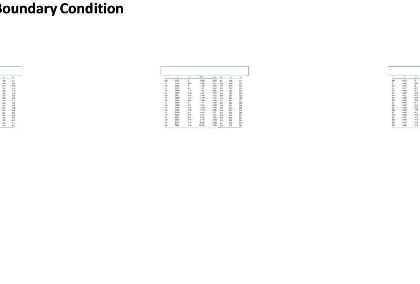
Table Infinitely Long Journal Bearing Solutions with the Reynolds
Table Infinitely Long Journal Bearing Solutions with the Reynolds
Boundary Condition
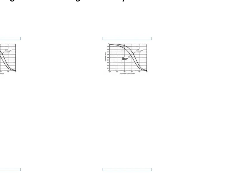
B. Full and Half
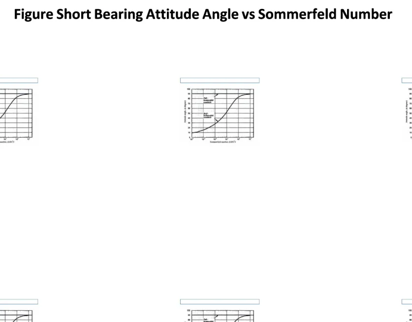
Figure Short Bearing
Figure Short Bearing Attitude Angle vs Sommerfeld Number
Figure Short Bearing Attitude Angle vs Sommerfeld Number
Darma
FINITE BEARING DESIGN &
FINITE BEARING DESIGN &
ANALYSIS
ANALYSIS
This section focused on design and
This section focused on design and
performance analysis based on the full
performance analysis based on the full
solution of Reynold equation.
FINITE BEARING DESIGN & ANALYSIS
FINITE BEARING DESIGN & ANALYSIS
FINITE BEARING DESIGN & ANALYSIS
FINITE BEARING DESIGN & ANALYSIS
•• Minimum filmMinimum film
thickness thickness
h
hminmin = C ( 1 = C ( 1– – Ɛ )Ɛ )
•• Friction forceFriction force
F = f W F = f W
•• Power lossPower loss
E
E p p= F 2π R N= F 2π R Nss
•• Temperature riseTemperature rise
ΔT ΔT==
FINITE BEARING DESIGN & ANALYSIS
FINITE BEARING DESIGN & ANALYSIS
FINITE BEARING DESIGN & ANALYSIS
FINITE BEARING DESIGN & ANALYSIS
••
Example:
Example:
A large pump has a horizontal rotor weighing 3200 lb supported
A large pump has a horizontal rotor weighing 3200 lb supported
on two
on two
plain 360
plain 360
oojournal bearings
journal bearings
, one on either side of the pump impeller. The
, one on either side of the pump impeller. The
specifications of the bearings are as
specifications of the bearings are as follo
follows:
ws:
R
R =
= 2
2 in
in
L
L =
= 4
4 in
in
C
C =
= 0.002
0.002 in
in
N
N =
= 1800
1800 rpm
rpm
the lubricant viscosity
the lubricant viscosity
µ = 1.3 x 10
µ = 1.3 x 10
-6-6reyns (SAE 10 at an inlet temperature
reyns (SAE 10 at an inlet temperature
of 166
of 166
ooF)
F)
Determine:
Determine:
a)
a)
Eq
Equil
uilibr
ibrium p
ium posi
ositio
tion of the s
n of the shaf
haft cen
t cente
ter and l
r and loca
ocatio
tion of fil
n of film rup
m ruptur
ture
e
b)
b)
M
Min
inim
imum
um fi
fillm
m th
thic
ickn
knes
esss
c)
c)
Lo
Loca
cati
tion
on an
and m
d mag
agni
nitu
tude
de of
of ma
maxi
ximu
mum p
m pre
ress
ssur
ure
e
d
d))
P
Po
ow
we
er
r llo
ossss
e
FINITE BEARING DESIGN & ANALYSIS
FINITE BEARING DESIGN & ANALYSIS
FINITE BEARING DESIGN & ANALYSIS
FINITE BEARING DESIGN & ANALYSIS
FINITE BEARING DESIGN & ANALYSIS
FINITE BEARING DESIGN & ANALYSIS
FINITE BEARING DESIGN & ANALYSIS
FINITE BEARING DESIGN & ANALYSIS
Muliyani
Muliyani
ATTITUDE ANGLE FOR OTHER BEARING
ATTITUDE ANGLE FOR OTHER BEARING
CONFIGURATION
CONFIGURATION
Where:
Where:
LUBRICANT SUPPLY ARRANGEMENT
LUBRICANT SUPPLY ARRANGEMENT
Supply Hole
Supply Hole
Axial Groove
Axial Groove
Circumferential Groove
Circumferential Groove
SUPPLY HOLE
SUPPLY HOLE
A common supply methode with small bearing and
A common supply methode with small bearing and bushing is to place bushing is to place an inlet portan inlet port
at the bearing midplane opposite to the load line
AXIAL GROOVE
AXIAL GROOVE
VARIOUS GROOVE POSITIONS AND
VARIOUS GROOVE POSITIONS AND
INLET ARRANGEMENT
INLET ARRANGEMENT
CIRCUMFERENTIALS
CIRCUMFERENTIALS GROO
GROOVE
VE
Alur yang melingkar
FLOW CONSIDERATION
FLOW CONSIDERATION
Where fL is a corretion factor for the film position as given below:
Where fL is a corretion factor for the film position as given below:
1.
1. Oil holOil hole or axiae or axial grol groove poove positiositioned in thned in the unloade unloaded sectied section of thon of the bearie bearing oppong opposite tsite too
the load line:
the load line:
2.
2. Oil hole or axial grOil hole or axial groove positionoove positioned at the maximum ed at the maximum film thicknessfilm thickness
3. For double axial grooves runn
3. For double axial grooves running parallel at ±90º angles to the ing parallel at ±90º angles to the load line:load line:
4. For a full film starting from the maximum film thickness position
FLOW CONSIDERATION
FLOW CONSIDERATION
Pressure Induced
Pressur
e Induced Flow
Flow
Inlet hole of diameter DH:
Inlet hole of diameter DH:
••
Qp : Pressure induced
Qp : Pressure induced
flow
flow
••
Ps : Supply pressure
Ps : Supply pressure
FLOW CONSIDERATION
FLOW CONSIDERATION
1.
1.
The film thickness parameter for an oil hole ar an axial groove
The film thickness parameter for an oil hole ar an axial groove
positioned in the unloaded section of the bearing opposite the load
positioned in the unloaded section of the bearing opposite the load
line is
line is
2. Positioned at the maximum film thickness
2. Positioned at the maximum film thickness
3. For double axial groove
Total leakage flow rate
Total leakage flow rate
1.
1. For For an oil an oil hole hole or or an axan axial grial groovoove posie positiontioned in ed in the unthe unloadeloaded sectd section oion of the f the bearibearingng
opposite to the load line
opposite to the load line
2.
2. For aFor an axian axial grol groove oove of lengf length Lg (Lg/L= 0.th Lg (Lg/L= 0.3 to 0.83 to 0.8) posit) positioned ioned at the mat the maximaximum filum filmm
thickness or two
Mulyani
Example 8.4
Example 8.4
•• Consider a journal bearing with the Consider a journal bearing with the follofollowing specification that correspond towing specification that correspond to
an actual bearing tested by Dowson et al , (1966):
an actual bearing tested by Dowson et al , (1966): L/DL/D = 0.75;= 0.75; R/CR/C = 800; D == 800; D = 0.102 m;
0.102 m; W W = 11000 = 11000 N, and operating speed isN, and operating speed is NNss= 25 rev/s.= 25 rev/s.
•• An axial groove was cut into the bearing surface in the unload portion of theAn axial groove was cut into the bearing surface in the unload portion of the
bearing, opposite the load line. the groove width is
bearing, opposite the load line. the groove width is ωωgg = 4.76 x 10- = 4.76 x 10⁻³³m, and it ism, and it is LLgg = = 0.067 m long. 0.067 m long. LubricanLubricant is t is supplied to the bearing at supplied to the bearing at tempertemperature Tature Tii = 36.8 = 36.8 o
oC at a supply pressure of PC at a supply pressure of P
ss = 0.276x10 = 0.276x1066 Pa (40 Psi) . The lubricant viscosity is a Pa (40 Psi) . The lubricant viscosity is a function of temperature and varies according to µ =
function of temperature and varies according to µ = µie µie--ββ(T-Ti)(T-Ti) with with µi µi = 0.03 Pa.s,= 0.03 Pa.s,
and the temperature viscosity coefficient is estimated to be
and the temperature viscosity coefficient is estimated to be
β
β
= 0.0414. = 0.0414.lubricant thermal cond
lubricant thermal conductivity k = uctivity k = 0.13 W/mK, and 0.13 W/mK, and thermal diffusivitythermal diffusivity ɑɑtt = 0.756 = 0.756 x 10-7 m
x 10-7 m22/s. Determine the flow rates, power loss, attitude angle, and maximum/s. Determine the flow rates, power loss, attitude angle, and maximum pressure.
pressure.
Paramete
Parameter r Nilai Nilai ParametParameter er NilaiNilai
L/D L/D 0.75 0.75 TTii 36.836.8ooCC R/C R/C 800 800 PPss 0.276x100.276x1066 Pa (40 Pa (40 Psi) Psi) D
D 0.102 0.102 m m µi µi 0.03 Pa.s0.03 Pa.s
W W 11000 N11000 N ββ 0.04140.0414 N Nss 25 25 rev/s rev/s k k 0.13 0.13 W/mKW/mK ω ωgg 4.76 x 10-4.76 x 10-33mm ɑɑ tt 0.756 0.756 x x 10-710-7 m m22/s/s L L 0.067 m0.067 m
••
Menggunakan rumus Sommerfeld number :
Menggunakan rumus Sommerfeld number :
<<
<<
0.03 25.0
0.03 25.0 0.0762 0.102
11000
11000
0.0762 0.102
800
800
0.338
0.338
Dari table 8.6 Dari table 8.6 dengan L/D = 0.75 dengan L/D = 0.75 didapat didapatɛ =͠ɛ =͠ 0.450.45••
Maka didapat
Maka didapat
Ǭ
Ǭ
LL
= 0.7821 ; (R/C) f = 7.4017; ɸ =
= 0.7821 ; (R/C) f = 7.4017; ɸ =
59.19
59.19
oo••
Sehingga
Sehingga
Leakage flow rate : Ǫ
Leakage flow rate : Ǫ
LL
=
=
Ǭ
Ǭ
LL
N
N
ssDLC
DLC
Ǫ
Ǫ
LL=
=
0.7821
0.7821
25 x 0.102 x 0.0762 x 6.35.10
25 x 0.102 x 0.0762 x 6.35.10
-5-5= 1,51.10
= 1,51.10
-3-3m
m
33/s = 15.1 c
/s = 15.1 cm
m
33/s
/s
Cara 2 dengan curve fit equation, table 8.8
Cara 2 dengan curve fit equation, table 8.8
= [ 1- 0.22 (0.75)
= [ 1- 0.22 (0.75)
1.91.9(0.45)
(0.45)
0.020.02= 0.875
= 0.875
ƒ
ƒ
LL= ɛ. ƒ
= ɛ. ƒ
11=
= 0.45
0.45 (0.875)
(0.875) =
= 0.394
0.394
=
=
π (0.762) (0.102)(25)(
π (0.762) (0.102)(25)(
6,35.10
6,35.10
-5-5)(0.394)
)(0.394)
= 1,52.10
= 1,52.10
-5-5m
m
33/s
/s
ƒ
ƒ
11= 1- 0.22
= 1- 0.22
1.91.9ɛ
ɛ
0.020.02 Ǫ ǪLL= π= π N N ssDLC DLC ƒ ƒ LL••
Attitude angle
Attitude angle
Asumsi h
Asumsi h
max
max
, δ = 0.18,
, δ = 0.18,
dengan menggunakan
dengan menggunakan
persamaan 8.45 dan 8.46 maka didapat :
persamaan 8.45 dan 8.46 maka didapat :
ɀ = 4
ɀ = 4
11 ++
((11 −− 11..225 5 εεᵟᵟ))
(8.46)
(8.46)
= 4
= 4
11 ++ 00..7755 ((11 −−11..225 5 00..4455
00..18
18
))
= 3.75
= 3.75
ɸ = tan
ɸ = tan
-1
-1
1−<
1−<
(8.45
(8.45 ))
= tan
= tan
-1
-1
1−0.45<
1−0.45<
= 59
= 59
o
o
••
Next, the pressure include flow must be
Next, the pressure include flow must be determined. Fro
determined. From table 8.8 determine the
m table 8.8 determine the
groov
groove function and
e function and the related film thickness :
the related film thickness :
=(1+ɸ)=
=(1+ɸ)=
((11 ++ 00..4455ccoos s 5599))== 11..8877
ƒ
ƒ 1.1.2255 −− 00..2255 0.0.0067
33 ((00..00776622/ / 00..006677))
67/0/0..007762
−− 11 ++
62
33 0.0.0076
762/2/00..110022 ((11 −− 0.0.0067
4.76 x 10ˉ=/0.102
4.76 x 10ˉ=/0.102
67/0/0.0.077662)2)
= 0.838
= 0.838
ƒ
ƒ 11..2255 −− 00..2255 //
33 ((/ / ))
−− 11 ++
33 // ((11 −− //))
ωω
gg//DD
Ǫ
Ǫ
pp=
=
ƒ
ƒ
ggℎ
ℎ
=
=
P
P
ss=
=
ᵢ
ᵢ
=
=
..
.
. ((..
)(.ˉ?)=
)(.ˉ?)=
.
.
=
=
3.69 x 10
3.69 x 10
-6-6m
m
33/s = 3.69 cm
/s = 3.69 cm
33/s
/s
S’ = 0.75 S’ = 0.75
0.70.7 + 0.4 + 0.4 = 0.75 = 0.75.
.
.
.
0.70.7 + 0.4 + 0.4 = 1.085 = 1.085Total leakage is determinated as follows. First, the datum flow rate
Total leakage is determinated as follows. First, the datum flow rate
Ǫ
Ǫ
mmis
is
estabili
estabilished
shed ::
Ǫ
Ǫ
mm=
=
Ǫ
Ǫ
LL+
+
Ǫ
Ǫ
pp–
–
0.3
0.3
ǪǪ
LL . .ǪpǪp
= 15.1 + 3.69
= 15.1 + 3.69
–
–
0.3
0.3
(15.1)(3.69)
(15.1)(3.69)
=
= 16.6
16.6 cm³
cm³/s
/s (16.
(16.6x10
6x10
-6-6m
m
33/s)
/s)
From table 8.8 for an axial groove
From table 8.8 for an axial groove
positioned in the unloaded section of
positioned in the unloaded section of
the bearing opposite to the load line,
the bearing opposite to the load line,
we have :
we have :
Therefore , the total leakage
Therefore , the total leakage
flow rate becomes :
flow rate becomes :
Ǫ
Ǫ
L totalL total=
=
Ǫ
Ǫ
mmSS’’Ǫ
Ǫ
p p 1-S1-S’’= (16.6)
= (16.6)
1.0851.085(3.69)
(3.69)
-0.085-0.085= 18.81 cm
= 18.81 cm
33/s
/s
(18.81 x 10
(18.81 x 10
-6-6m
m
33/s)
/s)
Power loss :
Power loss :
Ep = FU =
Ep = FU =
ƒW
ƒW
(2π R Ns)
(2π R Ns)
= 7.4017 (1/800) (11000) (π x 0.102 x 25)
= 7.4017 (1/800) (11000) (π x 0.102 x 25)
= 812 W (1.09 hp)
= 812 W (1.09 hp)
Dari therma
Dari thermal diffusivity,
l diffusivity,
ρCp
ρCp
= k/α
= k/α
tt= 1.72 x 10
= 1.72 x 10
66W.s/ (m
W.s/ (m
33K)
K)
∆
∆
(Ǫ
(Ǫ
••
Effectiive temperature for evaluating next iteration is
Effectiive temperature for evaluating next iteration is
(section 8.17)
(section 8.17)
T
T
cc= T
= T
ii+ ΔT = 36.8 + 25.1 = 61.9
+ ΔT = 36.8 + 25.1 = 61.9
ooC
C
••
The corresponding viscocity is :
The corresponding viscocity is :
µ =
••
Dengan diketahui viskositasnya, rasio eksentrisitas
Dengan diketahui viskositasnya, rasio eksentrisitas
dapat dihitung dengan
dapat dihitung dengan menggunak
menggunakan data dari tabel
an data dari tabel
8.9 dengan
8.9 dengan prediksi effective temperaturn
prediksi effective temperaturnya 50
ya 50
ooC
C
••
Dengan interpolasi didapat
Dengan interpolasi didapat
..
..
.
••
θmax−;
θmax−;
<
<
=
=
cos
cos
-1-1 .
.
(.)<
(.)<
= 138.13
= 138.13
ooC
C
••
Prediksi
Prediksi
θ
θ
maxmax=
=
138.13
138.13
ooC, which if measured from the load
C, which if measured from the load line
line
would be =
would be =
138.13
138.13
+
+
ɸ
ɸ
=
Dengan menggunakan
Dengan menggunakan tabel 8.6
tabel 8.6 maka
maka maximum pressurenya
maximum pressurenya
:
:
••
..
..
..
..
..
..
Ṕ.
Ṕ.
.
.
.
.
Ṕ.
Ṕ.
.
.
••Ṕmax13.24≅13
Ṕmax13.24≅13
••
<<
ṔṔmax max + P + Pss = (0.016) (25) (800) = (0.016) (25) (800)22 (13) + 2.67.105 (13) + 2.67.105 = 3.60 Mpa (520 Psi) = 3.60 Mpa (520 Psi)Circumferential Groove
Circumferential Groove
Ǫ
Ǫ
cc
′
′
((11 ++ 11..5 5
))
(8.61)
(8.61)
Ǫ
Ǫ
L totalL total= Ǫ
= Ǫ
LL+ 2
+ 2
Ǫ
Ǫ
cc(8.62)
(8.62)
Example 8.5
Example 8.5
Consider a plain
Consider a plain journal bearing with
journal bearing with the following specificati
the following specifications:
ons:
D
D
= 8 in; L = 4.00;
= 8 in; L = 4.00;
C
C
= 6x10
= 6x10
-3-3in; operating speed
in; operating speed
N
N
= 3600rpm. The
= 3600rpm. The
load imposed on the bearing is W= 4800lbf. A narrow
load imposed on the bearing is W= 4800lbf. A narrow
circumferential oil feed groove is cut into the bearing at is
circumferential oil feed groove is cut into the bearing at is
midlength, abd lubricant (
midlength, abd lubricant (
μ
μ
= 10 cp at
= 10 cp at
T
T
= 120
= 120
ooF) is supplied at 10
F) is supplied at 10
psi. determine the temperature rise.
psi. determine the temperature rise.
With the full length
With the full length
LL
= 4 divided in half,
= 4 divided in half,
l’/D
l’/D
= 0.25.
= 0.25.
Load of each two bearing segments is
Load of each two bearing segments is W W l l ’ ’ = =
24
24
00
00
Projected pressure on each bearing
Projected pressure on each bearing PPl’ l’ ==
( )
( )
15
150
0
Operati
Operating viscocity ng viscocity isis
μ
μ
= 10cp ( = 10cp ( 1.45x10⁻⁷) reyns/cp1.45x10-7) reyns/cp= 1.45 x 10⁻⁶ reyns
Sommerfe
Sommerfeld n
ld numbers :
umbers :
(/)<
(/)<
′
′
0.258
0.258
Operating eccentricity Ɛ= 0.8
Operating eccentricity Ɛ= 0.8
Dimensionaless
Dimensionaless
leakage
leakage flow
flow rate
rate Ǭ
Ǭ
LL= 1.5753
= 1.5753
Friction coefficient
••
In dimensional form, the leakage flow rate due to
In dimensional form, the leakage flow rate due to
shaft rotation is :
shaft rotation is :
Ǫ
Ǫ
LL= Ɛ
= Ɛ
NsDl’C
NsDl’C
= 0.8
= 0.8
60. 8. 2.
60. 8. 2.
610⁻
610⁻
= 14.25 in
= 14.25 in
33/s (14.25x60/231 = 3.70 gpm)
/s (14.25x60/231 = 3.70 gpm)
••
Pressur
Pressure-induce fl
e-induce flow is :
ow is :
Ǫ
Ǫ
cc
′
′
((11 ++ 11..5 5
))
=
=
(⁻
(⁻
)
)
..⁻@
..⁻@
((11 ++11..5 5 ((00..88))
))
= 3.06 in
= 3.06 in
33/s
/s (0.79
(0.79 gpm)
gpm)
••
Total leakage flow becomes
Total leakage flow becomes
Ǫ
Ǫ
L totalL total= Ǫ
= Ǫ
LL+ 2
+ 2
Ǫ
Ǫ
cc= 14.25 in
= 14.25 in
33/s + (2 x 3.06 in
/s + (2 x 3.06 in
33/s)
/s) =
= 20.37
20.37 in
in
33/s (5.29
/s
(5.29 gpm)
gpm)
••
Po
Power loss is for each half
wer loss is for each half-length bearing segment is :
-length bearing segment is :
Ep =
Ep = ƒW
ƒW
l l’ ’
π
π
D Ns
D Ns
= 0.01329 x 2400 x
= 0.01329 x 2400 x
π x 8 x 60
π x 8 x 60
= 4.81 x 10
= 4.81 x 10
44in.lbf/s (0.83hp)
in.lbf/s (0.83hp)
••
Prediction
Prediction temperatur
temperature
e rise
rise is :
is :
∆
∆ 2
(Ǫ
(Ǫ
2
,,
))
77778 8 1122 00..4488 00..00331155 ((2200..3377)) 33.4:
2 4.81.10>
2 4.81.10>
33.4:
Mean outlet temperature is
Mean outlet temperature is
T
BEARING STIFFNESS, ROTOR VIBRATION,
BEARING STIFFNESS, ROTOR VIBRATION,
AND O
••
Spring mass syst
Spring ma
ss system
em
Tia Utari
Determine whirl stability for a horizontal
Determine whirl stability for a horizontal
rotor and its bearings with
rotor and its bearings with the following
the following
characteris
characteristics
tics ::
D = 2R = 5 in D = 2R = 5 in L = 2.5 in L = 2.5 in C = 0.005 in C = 0.005 in N = 90 N = 90 rad/rad/s (5400 s (5400 rpm)rpm) Ks = 5 xKs = 5 x 10^6 lb/in rotor stiffness10^6 lb/in rotor stiffness W = 5000 lb rotor weight (m = W/
W = 5000 lb rotor weight (m = W/g = 5000/386 = g = 5000/386 = 13 lb13 lb
/in rotor mass/in rotor massμ
μ = 2 x 1 = 2 x 1
00
lbs/ lbs/
(reyns) viscosity (reyns) viscosityExample Example
8.6 8.6
Example Example 8.6 8.6Con’tCon’t
Analysis Using the
Analysis Using the graphgraph
Unit bearing load Unit bearing load P = P = (DL)(DL)
= = /
/
∗.
∗.
= 200 psi = 200 psi Sommerfeld number Sommerfeld number S = S = μμNN(/)
(/)
= 2*1 = 2*100
/
/
∗90/
∗90/
(. ∶. )
(. ∶. )
= 0.225 = 0.225Characteristic bearing number Characteristic bearing number = S(L/D = S(L/D
))
= 0.225 (2.5 in/ 5 in = 0.225 (2.5 in/ 5 in))
= 0.05625 = 0.05625Stability on rotor stiffness Stability on rotor stiffness (C/W)
(C/W)
= = (0.005 (0.005 in/ in/ 5000 5000 lb)*(5*1lb)*(5*100
lb/in) lb/in) = 10= 10
next next
Example Example 8.6 8.6Con’tCon’t Stability on case Stability on case (C/W)m
(C/W)m
ωω
= (0.005 in/ 5000 lb)*(13 lb
= (0.005 in/ 5000 lb)*(13 lb
/in*(2/in*(2ππ*90*90/)
/)
))
= 8.28= 8.28
Rotor will be free of Rotor will be free of
oil whip
General
General
Design
Design
Guides
Guides
Effective Effective Temperature Temperature Maximum Maximum Bearing Bearing Temperature Temperature Turbulent Turbulent and Parasitic and Parasitic Loss Effect Loss Effect Flooded Flooded versus versus Starved Starved Condition Condition Bearing Load Bearing Load Dimensions Dimensions Eccentricity Eccentricity and and Minimum Minimum Film Film Thickness Thickness Operating Operating Clearance Clearance Misalignment Misalignment and Shaft and Shaft Deflection DeflectionEff
Eff
ective
ective
T
T
emperature
emperature
Temperature rata-rata pada viskositas tertentu
Temperature rata-rata pada viskositas tertentu
Global effective temperature Global effective temperature
Dimana : Dimana :
JJ panas mekanik panas mekanik
ρ
ρ densitas oildensitas oil
leakage leakage flowrateflowrate
temperatur awal temperatur awal
kapasitas panas kapasitas panasΦΦ
conduction & radiation conduction & radiation
power loss power loss For small bearingMaximum Bea
Maximum Bea
ring T
ring T
emperature
emperature
Temperature Temperature Minimum Minimum film thickness film thickness
Turbulent and Parasitic Loss Effect
Turbulent and Parasitic Loss Effect
Turbulent : Turbulent :
•• Bearing diameterBearing diameter
•• Large film thicknesses Large film thicknesses (clearance)(clearance) •• High surface speedHigh surface speed
•• Low fluid viscositiesLow fluid viscosities •• High Reynolds numbersHigh Reynolds numbers
Par
Parasitic loss asitic loss ::
•• PutarPutaran dan an dan turbulensi pada oil turbulensi pada oil grooves dan clearencegrooves dan clearence
•• Losses pada percepatan feed oil terhadap surface speed yang tinggiLosses pada percepatan feed oil terhadap surface speed yang tinggi •• Vortex pada feed dan oil groovesVortex pada feed dan oil grooves
Flooded versus Starved Condotion Flooded versus Starved Condotion
Flooded Flooded Condition Condition
•
•
< 1
< 1
Starved
Starved
Condition
Condition
Leakage flow rate
Leakage flow rate
Kerja bearing jelek
Kerja bearing jelek
Good Cooling
Bearing Load and Dimensions
Bearing Load and Dimensions
Projected Loading Projected Loading
PL= W/(L*D) PL= W/(L*D)
Rentan
Rentan vibrasivibrasi Power loss tinggi Power loss tinggi
High oil flow High oil flow
overheating overheating