AYSIýs
UNIMPSý
I
IIN-SITU DETERMINATION
OF THE RESULTANT LOADING
IN STEEL REINFORCEMENT
USING ULTRASONIC
Chooi Chick Ngee
TA Bachelor of Engineering with Honours
417.2 (Mechanical Engineering and Manufacturing System)
C545 2004
BORANG PENYERAHAN TESIS
Judul: In-Situ Determination Of The Resultant Loadin9 In Steel Reinforcement Using Ultrasonic
SESI PENGAJIAN : 2003/2004
Saya CHOOI CHICK NGEE mengaku membenarkan tesis ini disimpan di Pusat Khidmat Maklumat Akademik, Universiti Malaysia Sarawak dengan syarat-syarat kegunaan seperti berikut:
1. Hakmilik kertas projek adalah di bawah nama penulis melainkan penulisan sebagai projek bersama clan dibiayai oleh Universiti Malaysia Sarawak, hakmiliknya adalah kepunyaan Universiti Malaysia Sarawak. 2. Naskhah salinan di dalam bentuk kertas atau mikro hanya boleh dibuat dengan kebenaran bertulis daripada
Universiti Malaysia Sarawak atau penulis.
3. Pusat Khidmat Maklumat Akademik, Universiti Malaysia Sarawak dibenarkan membuat salinan untuk pengajian mereka.
4. Kertas projek hanya boleh diterbitkan dengan kebenaran penulis atau Universiti Malaysia Sarawak. Bayaran royalti adalah mengikut kadar yang dipersetujui kelak.
5. * Saya membena-kaa/tidak membenarkan Perpustakaan membuat salinan kertas projek ini sebagai bahan pertukaran di antara institusi pengajian tinggi.
6. ** Sila tandakan (/) di mana kotak yang berkenaan SULIT
/
TERHAD
TIDAK TERHAD
(TANDATA GAN PENULIS)
Alamat tetap: No. 44A RAWANG TIN, 48000 RAWANG, SELANGOR. Tarikh: /S 3 . cX04 Catatan * ** Tarikh: I ýlýl(ý . 2da y Potong yang tidak berkenaan.
Jika Kertas Projek ini SULIT atau TERHAD, sila lampirkan surat daripada pihak berkuasa/organisasi berkenaan dengan menyertakan sekali tempoh kertas projek. Ini perlu dikelaskan sebagai SULIT atau TERHAD.
(Mengandungi maklumat yang berdarjah keselamatan atau kepentingan Malaysia seperti yang termaktub di dalam AKTA RAHSIA RASMI 1972).
(Mengandungi maklumat TERHAD yang telah ditentukan oleh organisasi/badan di mana penyelidikan dijalankan).
Disahkan oleh
j
(TTANDATX GANIPENYELIA)
APPROVAL SHEET
This project report, which entitled "In-Situ Determination Of The Resultant Loading In Steel Reinforcement Using Ultrasonic" was prepared by Chooi Chick Ngee as a partial fulfillment for the Bachelor's Degree of Engineering with Honours (Mechanical Engineering and Manufacturing System) is hereby read and approved by:
Dr. Ha How Ung (Project Supervisor)
Pusat Khk1mat lWa Iumat Akadendk uNIVERSITI MALAYSIA SARAWAK
94300 Kota Samarahao
IN-SITU DETERMINATION OF THE RESULTANT LOADING IN STEEL REINFORCEMENT USING ULTRASONIC
P. KNIDMAT MAKLUMATAKADEMK UNIMAS
MIIIIIIIIIIIIIIIIII
1000133637ZII
CHOOI CHICK NGEE
This project is submitted in partial fulfillment of the requirements for the degree of Bachelor of Engineering with Honours (Mechanical Engineering and Manufacturing System)
Faculty of Engineering
UNIVERSITI MALAYSIA SARAWAK 2004
Dedicated to my beloved family
ACKNOWLEDGEMENT
I would like to take this opportunity to give my sincere acknowledgement to
several individuals and parties that giving me a lot of helps and guidance throughout the period towards completing my final year project.
First of all, appreciation to my project supervisor, Dr. Ha How Ung, who had helped me in experiment's hardware preparation and had giving me a lot of guidance and
opinion in conducting the experiment and writing this report. Appreciation also to Dr. Sinin Hamdan, who had given me a lot of opinion and assistance during the report writing. Besides, Universiti Malaysia Sarawak, all lecturers of Engineering Faculty, supporting staffs and friends who had helped me either direct or indirectly in terms of budget allocation and opinion
provision.
Lastly, to Mr. Lim Soo Kiang of Chiat Feng Mechanical Works, who kindly gave
me a lot of cooperation in fabrication of required test rig and those gave me help but did not mentioned by each in this section.
ABSTRACT
In-situ loading determination is an on-site method that determine loading in the
original or natural place or site, which could give information of load within a structure instantly. This method eliminates the complicated and labourous processes involved in conventional loading determination method. It plays an utmost important role in condition monitoring of steel reinforced structural members such as post tensioned and pre-stressed concrete members whenever during fabrication stage or stage it serves the public. In this experimental study on specimen of mild steel, non-destructive testing (NDT) method of ultrasonic will be used based on acoutoelastic principle. Variation in flight time or wave speed variation of ultrasound within the specimen due to changes of resultant loading will be determined. Three samples or specimens of mild steel that assumed to be identical are used in this experiment. The results had shown the effect of stress-induced velocity changes but there were varying across samples and two samples do not exhibit the expected profile of graph due to some unavoidable factors. At the same time of experiment, strain gauge is used to obtain values of strain due to applied torque. In addition to applied torque, resultant loading is derived from values of strain. Confirmation test is performed by strain gauge on the resultant loading due to applied torque and the obtained ultrasound's velocity.
ABSTRAK
Penentuan bebanan in-situ ialah cara menentukan beban di tempat asal yang mana dapat memberikan maklumat tentang beban dalam suatu struktur serta-merta. Cara ini
mengelakkan proses rumit dan memenatkan yang terlibat dalam cara penentuan beban yang biasa. la memainkan peranan yang amat penting dalam pemantauan keadaan bahagian struktur yang diperkuatkan oleh keluli seperti bahagian konkrit pasca-tegang dan pra-tegasan semasa peringkat pembuatan atau memberi perkhidmatan kepada umum. Dalam pembelajaran ujikaji ke atas spesimen keluli ini, cara Ujian Tanpa Musnah ultrasonik akan digunakan berdasarkan prinsip `acoustoelastic'. Perubahan dalam masa terbang atau kelajuan gelombang ultrasonik dalam spesimen yang disebabkan oleh perubahan beban hasilan akan ditentukan. Tiga contoh spesimen keluli yang digunakan dianggap sama dalam ujikaji ini. Keputusan telah menunjukkan kesan perubahan kelajuan hasil daripada tegasan tetapi ia berbeza di kalangan contoh-contoh dan dua contoh tidak mempamerkan bentuk graf yang diharapkan kerana beberapa faktor. Semasa ujikaji, tolok keterikan digunakan untuk memperolehi nilai keterikan yang disebabkan oleh daya kilasan yang dikenakan. Selain daya kilasan, beban hasilan diterbit berasaskan nilai keterikan. Ujian pemastian dibuat dengan tolok keterikan terhadap beban hasilan yang dihasilkan daripada daya kilasan dan kelajuan ultrasonik yang diperolehi.
Pusat Khidmat Makiumat AkademII
UNIVERSITI MALAYSIA SARAWAK
941M Kota Samarahan
TABLE OF CONTENTS
NO. CONTENTS Dedication Acknowledgement Abstract Abstrak Table of Contents List of Tables List of Figures 1.0 Chapter 1: Introduction 1.1 Background 1.2 Ultrasonic 1.3 Project Objectives 2.0 Chapter 2: Literature ReviewPAGE ii iii iv V V1 Vlll ix I 2 4
2.1 Post-tensioning and Loading 6
2.2 Torque and Applied Load 8
2.3 Wave Speed and Material Factors 10
2.4 Ultrasonic and Stress Measuring 13
2.5 Constrains Of Stress Measuring By Using Ultrasonic 22 3.0 Chapter 3: Methodology
3.1 Specimen's Material For This Experimental Study 24 3.2 Types Of Loading And Experimental Test Rig To Imitate 26
The Loading On Specimen
3.3 Types Of Ultrasonic Waves And Ultrasonic Testing 26 Instrument
3.4 Calibration 28
3.5 Instrument Used In Confirming The Obtained Results 31 3.6 Comparison Study Of Ultrasonic Instrument's Readings 32
4.0 Chapter 4: Results and Discussion 35
4.1 Results
4.1.1 Specimen 1 36
4.1.2 Specimen 2 38
4.1.3 Specimen 3 40
4.2 Discussion 42
5.0 Chapter 5: Conclusion and Recommendation
5.1 Conclusion 54
5.2 Recommendation 55
6.0 References 57
7.0 Appendices
Appendix A - Drawing of Specimen (Sample) 60
Appendix B (i) - Drawing of Test Rig 61
Appendix B (ii) - Drawing of Test Rig 62
Appendix C - Acoustic Properties of Solids 63
Appendix D - Results In Form Of A-Scan For Specimen 1, 64 Specimen 2 And Specimen 3
Appendix E - Detail Results Of Specimen 1, Specimen 2 And 73 Specimen 3
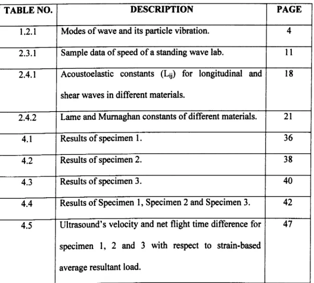
LIST OF TABLES
TABLE NO. DESCRIPTION PAGE
1.2.1 Modes of wave and its particle vibration. 4
2.3.1 Sample data of speed of a standing wave lab. 11 2.4.1 Acoustoelastic constants (Lid) for longitudinal and
shear waves in different materials.
18
2.4.2 Lame and Murnaghan constants of different materials. 21
4.1 Results of specimen 1. 36
4.2 Results of specimen 2. 38
4.3 Results of specimen 3. 40
4.4 Results of Specimen 1, Specimen 2 and Specimen 3. 42
4.5 Ultrasound's velocity and net flight time difference for specimen 1, 2 and 3 with respect to strain-based average resultant load.
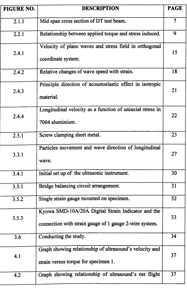
LIST OF FIGURES
FIGURE NO. DESCRIPTION PAGE
2.1.1 Mid span cross section of DT test beam. 7
2.2.1 Relationship between applied torque and stress induced. 9 Velocity of plane waves and stress field in orthogonal
2.4.1 15
coordinate system.
2.4.2 Relative changes of wave speed with strain. 18
Principle direction of acoustoelastic effect in isotropic
2.4.3 21
material.
Longitudinal velocity as a function of uniaxial stress in
2.4.4 22
7064 aluminium.
2.5.1 Screw clamping sheet metal. 23
Particles movement and wave direction of longitudinal
3.3.1 27
wave.
3.4.1 Initial set up of the ultrasonic instrument. 30
3.5.1 Bridge balancing circuit arrangement. 31
3.5.2 Single strain gauge mounted on specimen. 32
Kyowa SMD- I OA/20A Digital Strain Indicator and the
3.5.3 33
connection with strain gauge of 1 gauge 2-wire system.
3.6 Conducting the study. 34
Graph showing relationship of ultrasound's velocity and
4.1 37
strain versus torque for specimen 1.
4.2 Graph showing relationship of ultrasound's net flight 37
difference time and strain versus torque for specimen 1. Graph showing relationship of ultrasound's velocity and
4.3 39
strain versus torque for specimen 2.
Graph showing relationship of ultrasound's net flight
4.4 39
time difference and strain versus torque for specimen 2. Graph showing relationship of ultrasound's velocity and
4.5 41
strain versus torque for specimen 3.
Graph showing relationship of ultrasound's net flight
4.6 41
time difference and strain versus torque for specimen 3. Graph showing relationship of ultrasound's velocity and
4.7 43
strain versus torque for specimen 1, 2 and 3.
Graph showing relationship of ultrasound's net flight
4.8 time difference and strain versus torque for specimen 1, 44 2 and 3.
Graph showing relationship of ultrasound's velocity
4.9 47
versus resultant loading for specimen 1, 2 and 3.
Graph showing relationship of ultrasound's net flight
4.10 time difference versus resultant loading for specimen 1, 48 2 and 3.
Ultrasonic wave displayed on Panametrics Instrument.
4.11 (a) Wave of calibration block (25 mm). (b) Wave of 53
specimen 3 (1500 mm) third reading.
CHAPTER 1
INTRODUCTION
1.1 Background
Steel is categorized as ferrous metal and its application as structural members such
as I-beams in construction, bar products, axles and railroad rails are considered the most important technological development (S. Kalpakjian, 2001). Stress called residual stress are developed in steel during the forming and shaping of reinforcement steel at the stage of
production; however, these stresses are released during the end of production by stress-relief annealing and cause insignificant effect. However, as steel reinforcement functioning as structural members, various kinds of applied loads are experienced causing bending, tensioning or compressing and stresses are then developed within these structural members. Resultant loading during stages of structure fabrication and their service periods, thus, steel
reinforcement experiences stresses within the structural members, in which will give significant and crucial effect to the structure. For instance, brittle fracture will occur when structural members over loaded with substantial tensile stress, which could exists in form of nominal, residual or both (J. M. Barsom et al., 1987). So, by getting to know the resultant loading of structural members, indirectly, level of stresses in steel reinforcement, immediate
action could be taken to avoid fatal accidents and deterioration of structure caused by failure of steel reinforcement when stresses in structural members beyond the acceptable stress level.
As stress and load has an intimate relationship, thus, by determine the resultant loading on the structural members, the stress experienced will be known. In order to
determine and monitor the loading and stress experienced by structural members of steel
reinforcement during the servicing period and fabrication stages, some sort of in-situ determination method must be used. Non-destructive testing (NDT) method is favorable to accomplish in-situ determination of resultant loading, where, after the test the structural members do not require any repair of deterioration and structural members could be used safely without causing harms to users. This is because NDT is one in which there is no impairment of the properties and performance in future use of the object under examination (J. Blitz and G. Simpson, 1996). In this project, ultrasonic that will be described in more details in the following section is identified to determine the resultant loading within the steel, which according to J. Blitz and G. Simpson (1996), ultrasonic method is effectively a mechanical method.
1.2 Ultrasonic
According to J. Blitz and G. Simpson (1996), ultrasonic is the name given to study
and application of ultrasound. In other words, ultrasound is a type of sound, where the sound is produced when a pressure wave that generated by mechanical disturbances propagates through a medium (E. L. Cooper, 1999). The vibratory sound wave could exists in different frequency, the frequency with 16kHZ to 20kHz is at lower frequency, where this is the
audible range of sound for human (D. Ensminger, 1988). The sound above this audible range of human beings is called ultrasound, where the vibration of ultrasound is too fast to be heard by human.
As the findings of ultrasonic mentioned before, ultrasound needs medium to allow the propagation of waves from one point to another such as air, liquid and solid. In contrast,
ultrasound does not travel through the vacuum. The elastic property of medium is responsible for sustaining the vibration for propagation of waves; thus, ultrasonic wave is also termed as
elastic waves. Although the researches and studies of ultrasonic as a form of energy (D. Ensminger, 1988) had been started by human since World War I, nevertheless the utilization capability of such energy is bestowed to the animals such as bats, dolphins, moths etc. for purpose of locating foods, navigation and detecting danger.
Generally, the applications of ultrasonic by introducing ultrasonic waves into
medium are based on the intensity of ultrasonic. Applications of high intensity ultrasonic are intend to cause an effect on medium or its contents i. e. medical therapy or welding of plastics
and metals while application of low intensity ultrasonic are purposely to pass information via medium or learn something about the medium without changing the state of medium i. e. non- destructive testing of materials, medial diagnose and depth sounding. Ultrasonic that used in non-destructive testing (NDT) involves applications such as distance gauging, flaw detection and measuring parameters related to material structure i. e. elastic moduli and grain size (Jack Blitz and Geoff Simpson, 1996). By using low intensity ultrasonic in NDT, object under examination will not ruin or experiences changes in dimension and structure as long as the applied stresses of ultrasound waves not exceeding the elastic limit, thus, object could be used even after the examination.
From another perspective, modes of ultrasonic waves propagate in the medium
such as longitudinal wave, shear wave, Lamb wave, Love waves and Rayleigh waves also serve as basis for different applications of ultrasonic waves. Longitudinal and shear waves are useful in ultrasonic inspection while Rayleigh waves are useful because of its sensitivity
detecting surface defects. Modes of wave traveling within medium are influenced by types of
medium, medium of gases only capable of transmitting longitudinal waves, longitudinal and shear waves in liquids and large variety of waves in solids (D. Ensminger, 1988). The particle vibration in the wave differentiates each wave modes (Table 1.2.1).
Modes Of Wave Particle Vibration
Longitudinal Parallel to wave direction
Shear Perpendicular to wave direction
Plate wave - Lamb Component perpendicular to surface (extensional wave)
Plate wave - Love Parallel to plane layer, perpendicular to wave direction
Rayleigh Elliptical orbit - symmetrical mode
Table 1.2.1: Modes of wave and its particle vibration [ 18].
1.3 Project Objectives
By doing this project, there are several objectives that hope to be achieve, which listed as follow:
" Devise a method to determine resultant loading by using Non-Destructive Method (NDT) technique.
" Correlate the speed of ultrasound with resultant loading experienced by steel reinforcement.
" Correlate the results of NDT method to that obtained by direct strain gauge measurements. 4
Finally, it is hope that ultrasonic will be value-added for successful correlation of
resultant load and ultrasonic wave speed through the project and the application of ultrasonic could be broader as an inspection tool.
CHAPTER 2
LITERATURE REVIEW
References had been done to get information regarding the subject of study as
much as possible by mainly browsing the websites in the Internet. Besides that, books, journals, engineering magazines and thesis are also sources of information. The information that obtained is based on several topics that related to the interests of subject of this study.
2.1 Post-tensioning and Loading
An article entitled "Full-Scale Test of Prestressed Double-Tee Beam" in magazine
of Concrete International had shown how the prestressed and post-tensioned Double-Tee (DT) concrete beam (Figure 2.1.1) was fabricated by using prestressed tendons of carbon fibre- reinforced polymer (CFRP) and post-tensioned carbon fibre composite cable (CFCC). The investigation had been carried out by N. F. Grace et al. and observation on the condition of both types of tendons when applied with load during test also was done.
The test was carried out to examine the DT structure, prestressed and post- tensioned tendons. One of the results, which is of our interest is the test had showed the changes of force experienced by the post-tensioned tendon when the structure was loaded with external loading. During the stage of fabrication, the loading applied to the CFCC strands (post-tensioned tendon) was identified. Prior the test of DT beam with loading, the average force measured in CFCC tendons was 443 kN. When test was carried out with hydraulic jacks by applying load to the DT beam that consists of prestressed and
NEFMAC sheet Non-prestressing 10 mm (300 mm x 100 mm) Leadliae rods 2120mm -4 75mmý -Rz- #
1
0 r- 00 ýn M 0 -A, M M 298 mm 3 w --v 195mm t80-ýrý ý----R s v 210 mnd 210 -17 e- 215 mm 60 *: -7-:
... .. ýo AL 0 0 0 F " "Two-legged stainless steel Concrete topping stirrups 916 mm 2ý K 304 mm ý298 mm Iv- _-0 c. g. c of composite section s 6- -j ... of precast section ... C. &Y. 70 n= (TYP. ) Post-tensioning 40 mm CFCC strand PretensionMg 10 mm Leadline tendon, 1 0th row "0 9 0 --. I "" d T'f 'I w 00 n 1035 mm Wl vn IV i
H
I
Non prestressing 12.5 mm CFCC strand, 5th rowtensioned tendons until flexural failure reached and the collapsed of DT beam, all 60
prestressed CFPR tendons (prestressed tendons) within the structure were ruptured while neither one of the CFCC tendons (post-tensioned tendons) nor their built-in anchorages failed. However, when ultimate load was reached during the test, the force in the four post-tensioned strands were nearly doubled to 807 kN, which is 75% of the tensile capacity of the strands.
Thus, from this article, without considering material of the post tensioning
element, it shows that during the fabrication of post-tensioned concrete structure, when load is applied to the anchored post-tensioning element with whatever methods such as torque or hydraulic ram to tense the post tensioning element in order to introduce the compressive strain
within concrete structure, the post tensioning element will experience a measurable tensile loading. Furthermore, during the servicing period of the structure, external loading applied to the structure cause the post tensioning element to experience a more significant tensile loading.
2.2 Torque And Applied Load
In the thesis of L. P. Wong, which titled "Relationship Between Torque And Applied Load In A Bolt For Different Coefficient Of Frictions", the study of relationship between torque and applied load had been carried out by using bolt and nut assembly with variation of coefficient of frictions between the thread of bolt and nut.
The relationship of torque and applied load had been stated in two conditions, where with lubricant applied to the thread of bolt and nut that yields to a lower coefficient of friction and without lubricant that yields to a higher coefficient of friction. The test had been
carried out with applying a measurable value of torque by using torque wrench to the nut for tightening of bolt and nut assembly that was fitted in test rig and introducing loading in form of uniaxial stress to the bolt. Strain gauge is used simultaneously to measure the strain experienced by the bolt when the load was applied. Thus, by assuming that the elasticity modulus, E of steel is 200 GPa, the stress experienced by bolt was determined.
The results of study had shown that the stresses or applied load in the bolt (derived from bolt's strain) was proportional to the torque applied to it when the nut was tightened by a measurable torque (Figure 2.2.1). This relationship is valid for both conditions i. e. with and without lubricant. For the condition with lubrication that causes lower
coefficient of friction, the stresses that recorded are higher compare to the other for the same value of applied torque. The bolt may confront with problem of over loading, which could lead to damage of components and decrease of fatigue life. In contrast, the higher coefficient
of friction that caused by rusty thread recorded a lower stress and bolt is under tightening, which it may cause the problems like leakage and premature looseness of assembly.
f WMrou1 Moriow
4w
Mýfcýnc-
-
-ý
Mf ý - 7fV\ .... _, j a. rwwrý w s ý: M/ iýýýJ200
. _ have ý ... r! 1 at tit 1w I---äric. dm tbu 0 E-""-'1 The acxmul40 80 80 1 without Terqoe, s (Nm) lWbcicmt bott:.
Figure 2.2.1: Relationship between applied torque and stress induced [7].
2.3 Wave Speed And Material Factors
In a website, which titled "Properties Of Waves", according to T. Henderson, two investigations on relationship of wave speed and property of material that had been conducted
and mentioned, which were "Exploring Waves Simulation" and "Speed of Standing Wave Lab".
In the "Exploring Waves Simulation", it was aimed to study the effect of wave
properties and properties of medium on wave speed. In this simulation, the properties of a wave such as frequency, wavelength, and amplitude were altered systematically followed by properties of medium such as mass density, spring constant, and damping coefficient to observe their effects to wave speed. The result from the simulation showed that wave speed was independent of wave properties. The wave speed, in contrast, was dependant on the properties of medium or material.
In another investigation called "Speed of Standing Wave Lab" that studies the
relationship between characteristics of waves speed and the medium or material factor i. e. tensile stress of medium. In the investigation, several waves were generated within a rope of a measurable tension with a generator. The characteristics of waves such as wavelength, frequency and speed were determined. Mathematically, as equation (2A), speed of sound
Wave speed = wavelength x frequency (2A)
wave is equivalent of multiplication of wavelength and frequency. Thus, frequency of generator vibration was then altered systematically to observe the changes of wave speed. After that, the characteristic of medium i. e. tensioning of rope was increased to study the
effect of tensile stress within the rope to wave speed. From the investigation the result that obtained was as shown in Table 2.3.1.
Trial Tension (N) Frequency (Hz) Wavelength (m) Speed (m/s)
1 2.0 4.05 4.00 16.2 2 2.0 8.03 2.00 16.1 3 2.0 12.30 1.33 16.4 4 2.0 16.25 1.00 16.3 5 2.0 20.25 0.800 16.2 6 5.0 12.8 2.00 25.6 7 5.0 19.3 1.33 25.7 8 5.0 25.45 1.33 25.5
Table 2.3.1: Sample data of speed of a standing wave lab [ 16].
As a result, it could be concluded that the changes of vibration frequency did not change the value of wave speed instead the wavelength, where the small variation of wave speed might be caused by experimental errors. On the other hand, by altering the tensioning of rope from 2N to 5N, obviously, the value of wave speed was changed. The wave speed is significantly faster in a material that has higher tensile stress.
In an article, which titled Bolt Stress Measurement Using Ultrasonic, it had mentioned that the travel speed of longitudinal wave of ultrasonic is determined by properties of materials or material factors such as density, temperature and stress. As a fastener is tightened and stretched, it experiences tensile stress and velocity of ultrasound travel through the fastener will decrease. In order to make changes on sound velocity, the applied stress
must be in same direction as the travelling direction of ultrasound. Thus, stress due to shear
![Table 1.2.1: Modes of wave and its particle vibration [ 18].](https://thumb-ap.123doks.com/thumbv2/123dok/4618737.3374706/17.849.82.729.315.670/table-modes-wave-particle-vibration.webp)
![Figure 2.1.1: Mid span cross section of DT test beam [8].](https://thumb-ap.123doks.com/thumbv2/123dok/4618737.3374706/20.1258.132.1117.59.640/figure-mid-span-cross-section-dt-test-beam.webp)
![Figure 2.2.1: Relationship between applied torque and stress induced [7].](https://thumb-ap.123doks.com/thumbv2/123dok/4618737.3374706/22.838.141.606.756.1029/figure-relationship-applied-torque-stress-induced.webp)
![Table 2.3.1: Sample data of speed of a standing wave lab [ 16].](https://thumb-ap.123doks.com/thumbv2/123dok/4618737.3374706/24.838.61.746.209.477/table-sample-data-speed-standing-wave-lab.webp)
