THE DEVELOPMENT OF ANTENNA FOR INDOOR WIRELESS LOCAL AREA NETWORK APPLICATION
By
WAN SALWANI BT WAN ROSLI
FINAL PROJECT REPORT
Submitted to the Department of Electrical & Electronics Engineering in Partial Fulfilment of the Requirement
for the Degree
Bachelor of Engineering (Hons) (Electrical & Electronics Engineering)
Universiti Teknologi PETRONAS Bandar Seri Iskandar
31750 Tronoh Perak Darul Ridzuan
Copyright 2013 by
Wan Salwani Bt Wan Rosli, 2013
CERTIFICATION OF APPROVAL
THE DEVELOPMENT OF ANTENNA FOR INDOOR WIRELESS LOCAL AREA NETWORK APPLICATION
by
Wan Salwani Bt Wan Rosli
A project dissertation submitted to the
Department of Electrical & Electronic Engineering Universiti Teknologi PETRONAS
in partial fulfilment of the requirement for the Bachelor of Engineering (Hons)
(Electrical & Electronic Engineering)
Approved:
__________________________
Dr Zuhairi bin Hj. Baharudin Project Supervisor
UNIVERSITI TEKNOLOGI PETRONAS TRONOH, PERAK
SEPTEMBER 2013
CERTIFICATION OF ORIGINALITY
This is to certify that I am responsible for the work submitted in this project, that the original work is my own except as specified in the references and acknowledgements, and that the original work contained herein have not been undertaken or done by unspecified sources or persons.
Wan Salwani Bt Wan Rosli
i
ABSTRACT
In wireless technology, one of the recently technologies used to have a good performance of antenna is Dielectric Resonator Antenna (DRA). The dielectric resonator antenna (DRA) consists of superior performance features such as it can be fabricated using a high dielectric constant material, covers wide range of frequency band: f = 0.7-35 GHz, exhibits high radiation efficiency (95%), excitable through different transmission lines and it can be fabricated in different shapes such as rectangular, cylindrical and hemispherical. The small size of the DRA makes it suitable element for antenna arrays. One of the DRA shapes that have been considered is cylindrical shape. The two elements of CDRA array design which feeding by rectangular aperture coupled slots is computed and analysed by using CST Microwave studio and Agilent network analyser.
i
ACKNOWLEDGEMENT
First of all, I would like to thank ALLAH the Almighty who has given me strength and blessings to complete my final year project I and II. I have taken efforts in this project. However, it would not have been possible without the kind support and help of many individuals and organizations. I would like to extend my sincere thanks to all of them.
I am highly indebted to my supervisor, Dr. Zuhairi bin Hj Baharudin for his guidance and constant supervision as well as for providing necessary information regarding the project and also for their support in completing the project. I would like to express my gratitude towards Mr. Affan Aziz Baba as a Graduate Assistance (GA) for his kind co-operation and encouragement which help me in completion of this project.
My whole thanks and appreciation to my fellow friends and family for their support which made me successfully completed my final year project and people. Besides that, my deepest gratitude goes to the people surrounding who have willingly helped me out with their abilities. Lastly, I would like to thank Universiti Teknologi PETRONAS (UTP), especially the Electrical and Electronics Engineering Department whereby students are given the opportunity to be trained with essential skills to excel in theoretical and practical work.
ii
TABLE OF CONTENT
1. Introduction... 1
1.1 Background of study ... 1
1.2 Problem Statement ... 2
1.3 Significance of the Project... 2
1.4 Objective ... 3
1.5 Scope of Study ... 3
1.6 The relevancy of the Project ... 3
1.7 Feasibility of the Project ... 4
2. Literature Review ... 5
2.1 Dielectric Resonator Antenna ... 5
2.2 Geometry of DRA ... 5
2.3 CDRAs Linear Array ... 6
2.4 Feeding Mechanism for DRA Excitation ... 7
3. Methodology ... 8
3.1 Study the CDRAs array in WLAN applications ... 8
3.2 Design Development of Block Diagram ... 8
3.2.1 CST Microwave Studio Design ... 9
3.2.2 Fabrication process... 12
3.2.3 Testing and Measurement process ... 13
3.3 Tools and Equipment ... 15
3.3.1 Designing the Antenna ... 15
3.3.2 Fabrication of Antenna ... 15
3.3.3 Testing and Measurement of Antenna ... 16
3.3.4 Final Year Project schedule and Submission dateline ... 17
3.3.5 Project Activities and Milestone ... 17
4. Result and Discussion ... 18
4.1 Design CDRAs Linear Array in Fabrication on PCB ... 18
4.2 CST Simulation and Measured result ... 19
4.2.1 Return Loss ... 20
4.3.2 Far field radiation pattern in CST simulation and S-21 Parameters Network Analyzer test ... 21
5. Conclusion and Recommendation ... 24
iii
5.1 Conclusion ... 24
5.2 Recommendation ... 24
6. References... 25
7. APPENDICES ... 28
iv
LIST OF FIGURES
Figure 1 : Types of DRA that normally being used in antenna design ... 6
Figure 2 : CST Microwave Studio software ... 9
Figure 3 : Substrate plane with FR-4 for CDRA array design ... 9
Figure 4 : parameters of substrate, ground plane and micro strip line ... 10
Figure 5 : Stub length of microstrip transmission line ... 10
Figure 6 : Two element of CDRA array at the (a) front view and (b) back view ... 11
Figure 7 : PCB board at front view of CDRA array design ... 12
Figure 8 : PCB board at back view of CDRA array design ... 12
Figure 9 : CDRAs array was connected to Agilent network analyser cable port ... 13
Figure 10 : Setup for measure the two-dimensional far field patterns ... 14
Figure 11 : CST Microwave Studio software logo ... 15
Figure 12 : Comparison between CDRAs and 50 cent sizes ... 16
Figure 13 : Agilent Network Analyser for S21 parameter ... 17
Figure 14 : Front view of antenna array planar in Gerber and PCB board ... 18
Figure 15 : Back view of antenna array planar in gerber and PCB... 19
Figure 16 : Comparison of the size between CDRA and 50 cent ... 19
Figure 17 : Return loss (dB) in S11 parameter simulated ... 20
Figure 18 : S11 Return loss (dB) in S11 parameter measured ... 20
Figure 19 : Far field radiation pattern in simulated result ... 21
Figure 20 : Far field radiation pattern in measured result ... 22
v
LIST OF TABLES
Table 1 : Dimension of Cylindrical Dielectric Resonator Antenna array design ... 11
vi
LIST OF ABBREVIATIONS
WLAN Wireless Local Area Network
DRA Dielectric Resonator Antenna
CDRA Cylindrical Dielectric Resonator Antenna CST Computer Simulation Technology
dBi Decibel of an Isotropic
PCB Printed Circuit Board
1 CHAPTER 1 INTRODUCTION 1. Introduction
1.1 Background of study
Currently, most of the WLAN technologies operating at frequency 2.4 GHz are widely used in industrial as well as in corporate, public and home environments following IEEE 802.11 b/g/n standards. However, the growing demands from the internet users have changed the world to develop to a better performance in wireless network and standardized around the world such as IEEE 802.11a which operating at 5.6 GHz. Wireless LANs are fast, flexible, cheap and can provide wideband wireless connectivity to multiple electronic user devices which suitable for local area network such as in corporate buildings, public and residential areas. One of the greatest technologies that have been proposed for WLAN application is Dielectric Resonator Antenna (DRA) technology. The conventional of Dielectric Resonator (DR) technologies has been applied as a filter and oscillator applications in early 1960’s.
Since then, the Dielectric Resonator (DR) continues growing and increasing demands on dielectric resonator technology until it achieved a great technology in communication system.
DRA has various geometries such as cylindrical, spherical, rectangular, disk and hemispherical [6]. In order to have good performances of antenna, the size and the type of DRA geometry that is used in designing antenna must be considered. Most modern world has implemented DRA which can operate at higher frequency bands of the system which 802.11b/g Wireless Local Area Network (WLAN). Many advantages of DRA such as low cost in fabrication, smaller in size, wider in bandwidth [1], high dielectric constant, high quality factor, high radiation efficiency and can radiate at wide range of frequencies [4,6,8]. DRA is suitable used in many communication systems such as tunnels and underground mines application because of its zero conductor losses and suitable for microwave band scale.
To achieve a better performance of DRA, some of the method has been introduced such as linear array antenna. Array antenna is the combination of two or more DRA that involved on the linear planar which gives a smaller and compact in size of
2
antenna. The antenna gain could be increased because of its small size and lightweight [3,7]. Instead of that, the antenna designers found out several techniques of feeding mechanisms and coupling to DRA that can be applied on Dielectric Resonator Antenna (DRA) designs thus enhance the better performance of antenna in wireless application.
1.2 Problem Statement
Recently, the continuing growth in demand for wireless LANs communications requires a good system for the devices in transferring or sharing the data or information. This kind of higher demands has pushed the industry to develop and improve more with a better technology and system. For conventional patch antenna technology possesses conductor and surface wave losses at millimetre wave frequencies which degrade the antenna performance which is low in bandwidth and the low gain of antenna.
Several factor which can affect the performance of bandwidth in antenna applications. Some of the previous design had been implemented in low dielectric constant. In this case, the effect of low dielectric constant of antenna give a very low radiation in Q-factor and the resonant frequency will be higher. Thus the antenna will be obtained a lower bandwidth and low in gain. Because of that, the efficiency of radiation will become lower and the return loss of antenna design will be more than - 10 dB, which indicate that the antenna absorbs less of fed power. Various techniques have been used to enhance the operational bandwidth in order to achieve the target or desired result.
1.3 Significance of the Project
Today, internet is one of the greatest networks in communication system and it becomes very important for people’s needs. The significance of this project is wireless network can be connected to multiple users for local area network such as in the building, for residential areas and etc. By doing this project, it can fulfil the user’s demands and gives a better performances in WLAN application.
3 1.4 Objective
In overall, the project focused more on the process of designing and fabricating a prototype of antenna which considerable in high gain (>5dBi) and bandwidth of the antenna (5.35 GHz to 5.85 GHz) by applying its operating frequency band is 5.6 GHz. Based on the design, the project has been fabricated, tested and measured to obtain for a better performance of DRA in indoor wireless application. The objectives of the project are as the following:
To study the principle of indoor antenna for WLAN application.
To design and fabricate a prototype of antenna with highly efficient at 5.6 GHz of operating frequency for IEEE 802.11a WLAN application.
To test and measure the performance of antenna in wireless application.
1.5 Scope of Study
This project focuses on the designing and fabricating of two elements CDRAs linear array. The operating frequency value that has been applied for CDRAs array is 5.6 GHz as per standard IEEE 802.11a WLAN application. Basically 5.6 GHz of operating frequency produce wideband and more channels which in range of 5.35 GHz to 5.85 GHz and high gain which is about 5 dBi and more. The designing and simulation process was done by using Computer Simulation Technology (CST) Microwave design software and the CDRAs array was being tested and measured by using Agilent network analyzer.
1.6 The relevancy of the Project
Since the WLAN application is one of the important needs to the people in their daily life, so by developing the antenna for indoor in WLAN application is very relevant and important to fulfil the demands of the internet users. On the same time, this project can enhance a better performance of WLAN application and thus it can be commercialized.
4 1.7 Feasibility of the Project
This project involved in software and hardware design. The methods used to complete the project were designing and simulating the antenna arrays, thus continued with the fabrication of the antenna design. This whole project was completed within the time period given as scheduled in the project Gantt chart as shown in Appendix III.
5
CHAPTER 2 LITERATURE REVIEW
2. Literature Review
2.1 Dielectric Resonator Antenna
Dielectric Resonator Antenna is the most suitable design that can be able to obtain a great performance in improving wider bandwidth, high gain and also highly efficient when it is being applied at millimetre wave frequency [1-2]. The bandwidth and resonant frequency of Dielectric Resonator Antenna (DRA) depends on the shape, dielectric constant material, radiation mode, dimension of DRA parameter and also excitation method such as aperture-coupling feed, direct-micro strip line feed, coplanar wave guide feed and etc. Some of the advantages of Dielectric Resonator Antenna (DRA) are low cost, small in size, ease of fabrication, high dielectric constant as , high gain and high radiation efficiency due to zero metallic and surface-wave losses [11] that contributes on a great performance of antenna especially in Wireless Local Area Network (WLAN) applications [3].
2.2 Geometry of DRA
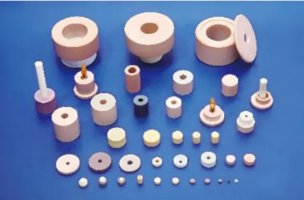
These are several of Dielectric Resonator Antenna (DRA) shapes or geometries such as cylindrical, rectangular, hemispherical, disk, spherical and half-split cylindrical [4,6]. Among of those shapes, cylindrical Dielectric Resonator Antenna (CDRA) is most widely used in recently wireless technology because of its more compact size and it is more directional which radiate greater power in one or more directions and thus can improve in wireless application with high gain and great bandwidth [5].
6
Figure 1 : Types of DRA that normally being used in antenna design
2.3 CDRAs Linear Array
Some applications in communication technology, several DRAs are combined together to form an array since it can improve the gain of antenna design [9]. The combination of antenna will reduce the gap between each of antenna model and thus produce a compact size [14] of prototype antenna. This compact size of antenna can enhance the great efficiency of antenna design. For Cylinder Dielectric Resonance Antenna arrays have three types of array such as two-element broadside array, four- element linear array and four-element planar array. According to the experiment [13], the two-element broadside array can enhance the performance of bandwidth in single DRA compared to other types. However, for the combination of antenna configuration, four-element linear array shows the best element to improve the wideband of bandwidth and gain.
The concept of array antenna, analysis of data and computer simulation of the cylindrical array antenna will be presented according to Ultra wide band impulse (UWBI) signals. Cylindrical array antenna allows for wide angular coverage in azimuth and elevation plane [17]. Several parameters are used to control the antenna design such as the array dimension, the distance between discrete array elements, the side lobe levels, the directivity, the first null beam with and half power beam with [16].
7 2.4 Feeding Mechanism for DRA Excitation
Many types of feeding mechanisms that can be used in DRA design such as the coaxial probe, a micro strip line coupled to a narrow slot which placed directly on the conducting plane and the feeding mechanism is isolated from the radiating region of signal [19]. Several types of excitation design of DRA which consists of three main shapes: hemispherical, cylindrical and rectangular. Some examples for cylindrical shape are split-cylinder DRA, cylindrical-ring DRA, electric monopole DRA, disk- loaded cylindrical DRA and etc. Each of the excitation shapes of DRA depend on the application that have been used [8]. The type of excitation will eliminate the conduction losses due to the feeding structure. The combination of two coupled resonators can be designed properly to increase the bandwidth and instantaneously to enhance the frequency scanning range [19].
According to the experiment [20] that has been carried out, the bandwidth of the resonant modes can be enhanced by using hybrid structure comparing to the conventional DRA. Most of the DRA design is depending on the value of dielectric constant that is being used to obtain the desired result. By adjusting the effective dielectric, the value of radiation Q-factor can be controlled. Due to the reason of air gap, the effective dielectric constant of the DRA becomes lower in Q-factor but increase in resonant frequency. The bandwidth can be expanded due to the reducing Q-factor and therefore increase in gain.
8
CHAPTER 3 METHODOLOGY
3. Methodology
This section will discuss the detail explanation of methodology that is used upon completing the project. In this project, there are several steps while completing the project which consists of the study about two elements of CDRAs planar array in WLAN applications, designing and simulating the CDRAs array, fabrication, and lastly testing and measuring the CDRAs array design as referred to the flow chart of the project in Appendix I.
3.1 Study the CDRAs array in WLAN applications
This project work started on preliminary research of the antenna for indoor wireless LAN application. Based on the study part, the author reviewed and studied some of the previous research papers on the technology of CDRA in WLAN applications before proceeding to designing part.
3.2 Design Development of Block Diagram
Several of procedures were considered in order to complete this project work in successfully. From the study, this project focused more on understanding of project background which is about CDRA technologies and how CDRAs planar array was applied in WLAN applications. The collection of data should be based on the type of DRA shape, parameter of antenna design, desired bandwidth and gain that could be achieved, operating frequency of DRA and the feeding mechanisms used in exciting the antenna. By considering these criteria, the next stage has been proceeding with the designing of antenna.
9 3.2.1 CST Microwave Studio Design
This part describes the design of CDRAs array in CST Microwave Studio (in Fig 2) for 802.11a WLAN applications at 5.6 GHz operating frequency. This software was used to optimize the design parameters of CDRAs array and simulate the design to get the desired results.
Figure 2 : CST Microwave Studio software
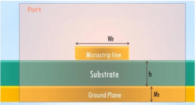
By using this CST software, the parameters and the dimension was set up according to the type of antenna shape and the operation type of radiating mode. Designing part in CST Microwave consists of designing ground planar, substrate and also CDRAs array on microstrip line as illustrated in Fig.4.
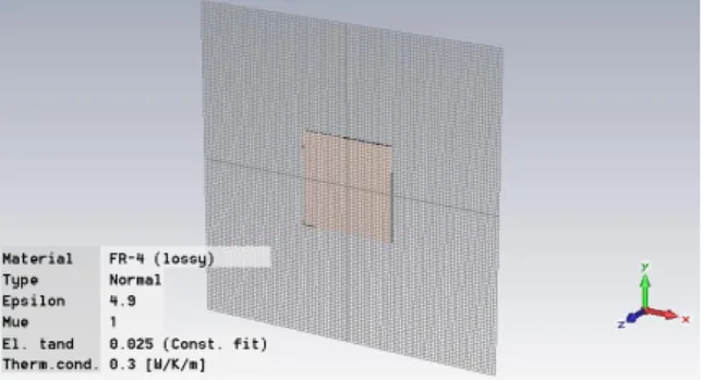
The first step of designing antenna arrays was designing the substrate planar by using FR-4 material and the epsilon, that is used 4.9 as shown in Figure 3.
Figure 3 : Substrate plane with FR-4 for CDRA array design
The substrate was designed on the FR-4 planar with 36 x 30 (mm) as same as the parameters for ground plane with copper material.
10
Figure 4 : parameters of substrate, ground plane and micro strip line
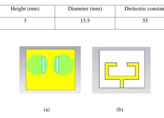
Referring to the Fig 6(a), the two element CDRAs planar array were feed by two rectangular aperture coupled slots technique was designed on the ground plane of 1.565 mm FR-4 substrate with 4.9 permittivity at front view of planar. These slots were used to excite the radiating elements of two elements of CDRA array. While at the back view of antenna substrate Fig 5(b), the series stub matching of microstrip transmission line was designed so that the power in and power out could be transferred through resonant frequency connector.
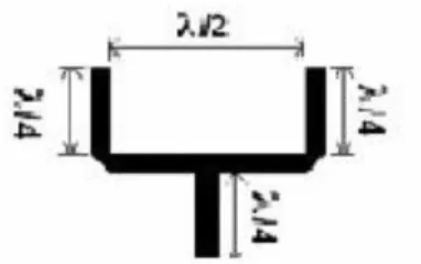
The 50Ω of microstrip feed line was used to excite the two mutual rectangle slots on the ground plane. The stub length, L of microstrip line as illustrated in Fig 5 can be calculated by using equation 1 and 2.
(1)
(2)
where wavelength, can be calculated by using equation (3).
Figure 5 : Stub length of microstrip transmission line
11
The value of wavelength, is given as
(3)
Where :
c : speed of light (3 X 10^8 m/s) f : resonance frequency
: permittivity of the dielectric material
The dimension of two elements CDRA in table 1 and the operating frequency was set up to 5.7 GHz for this design and the expected result would be shown.
Table 1 : Dimension of Cylindrical Dielectric Resonator Antenna array design
Height (mm) Diameter (mm) Dielectric constant
3 15.5 55
(a) (b)
Figure 6 : Two element of CDRA array at the (a) front view and (b) back view
12 3.2.2 Fabrication process
In fabrication part, the antenna array planar design from the simulation design in CST Microwave Studio software was converted into Printed Circuit Board (PCB) which is FR-4 board by using CST Gerber view. After designing part of array antenna has completed, the CDRA array were fabricated in PCB laboratory based on the design conversion in Gerber. Figure 7 and 8 show the PCB board on the antenna planar design which is in Gerber view. The fabrication of PCB took about two weeks to be completed.
Figure 7 : PCB board at front view of CDRA array design
Figure 8 : PCB board at back view of CDRA array design
13
3.2.3 Testing and Measurement process
The last stage of this project, the design tested and measured by using Agilent Network Analyzer to obtain the desired result. The Agilent Network Analyser used to analyse and determine the range of bandwidth value and the gain that could be achieved by two elements CDRA planar arrays to improve the efficiency of antenna in WLAN application. This process focused more on wider bandwidth range and high gain of far field radiation pattern or Fraunhofer Region of CDRAs array.
The bandwidth range was tested by using Agilent network analyser referring to S11 parameter. The network analyser port was connected to RF connector at CDRAs array as shown in Fig.9 and the result of S11 parameter was being analysed in result and discussion part.
Figure 9 : CDRAs array was connected to Agilent network analyser cable port
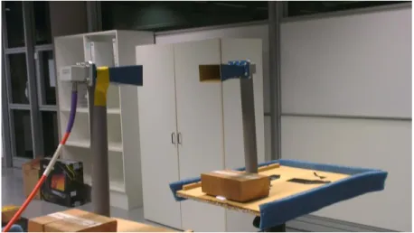
To measure the two-dimensional far field patterns, a setup similar to the one shown in Fig 10 is typically used. Firstly, CDRAs planar array or antenna under test (AUT) was mounted at the stable tripod or holder opposite to the reference antenna as illustrated in Fig.10. The reference antenna (transmitter) was connected to port 1 of the network analyser while CDRAs array (receiver) connected to port 2. The separation R between transmit and receive towers has to be great enough for the two antennas to appear in each other’s far field. The
14
distance between two antennas, transmitter and receiver was calculated by using the formula in equation 4.
(4) Where D represents the largest antenna dimension, and is the wavelength of operation. The frequency range of interest was set up on the network analyser.
Figure 10 : Setup for measure the two-dimensional far field patterns
15 3.3 Tools and Equipment
To conduct the project work, which the antenna needed to be fabricated, thus the test and measurement of the antenna performance can be conducted. The consumable tools and equipment that involved in this project are categorized by these three components which involved in designing, fabrication, and testing and measurement process.
3.3.1 Designing the Antenna
To design the antenna, first step is to determine the antenna geometry.
Based on preliminary research, the geometry of the antenna has been selected and the parameters of the design can be set up by using Computer Simulation Technology (CST) microwave software.
CST Microwave Design – CST Microwave Design is being used to carry on the simulation of Dielectric Resonator Antenna (DRA) design. This software also enables to simulate and analyse the result of antenna design accurately which is for high frequency devices.
Figure 11 : CST Microwave Studio software logo
3.3.2 Fabrication of Antenna
After the antenna has been designed with appropriate parameters, the antenna will be fabricated at Fabrication Laboratory. To conduct this fabrication process, all the antenna tools and equipment would be prepared in Fabrication Lab.
Cylindrical Dielectric Resonance Antenna (CDRA) – This is the main components of the antenna which function as to radiate the signal of communication. The parameters and dimension of this
16
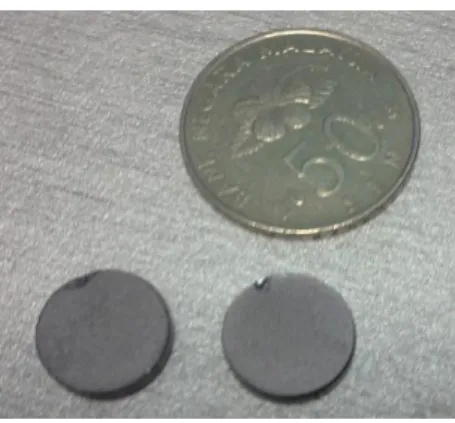
CDRA will be set up to simulate in the software design. Figure 12 shows the CDRA size is very small compared to 50 cent size.
Figure 12 : Comparison between CDRAs and 50 cent sizes
FR-4 board – The prototype of antenna design that is CDRA was implemented to this type of board which function as a planar substrate.
3.3.3 Testing and Measurement of Antenna
This is the last process of the project that is very important to indicate that the antenna is in good performance in terms of bandwidth, gain, and efficiency of the system. The data was collected and analysed based on the results of testing and measuring of antenna design. To apply this process, the CDRAs array was tested and measured by using Agilent network analyzer.
Agilent Network Analyzer – This equipment used to measure the S11 and S21 parameters of bandwidth range and also the gain far field radiation pattern of antenna.
17
Figure 13 : Agilent Network Analyser for S21 parameter
3.3.4 Final Year Project schedule and Submission dateline
The Final Year Project I and II flow chart schedules and submission date are depicted in Appendix II and Appendix III respectively.
3.3.5 Project Activities and Milestone
The project activities and milestone during Final Year Project I and II are depicted in Appendix IV and Appendix VI respectively.
18 4. Result and Discussion
4.1 Design CDRAs Linear Array in Fabrication on PCB
Based on the Figure 14, it shows the design at front view on (a) gerber view which converted from the design in CST Microwave Studio and also on PCB board view after the antenna planar fabricated completely. These two rectangle aperture coupled slots technique were excited through 50 Ω microstrip feed line which made up of copper materials. The two same sizes of CDRA arrays were feed on these two slots.
(a) Gerber view (b) PCB board view
Figure 14 : Front view of antenna array planar in Gerber and PCB board
As in Figure 15 illustrated, it shows the antenna planar design at back side view on (a) gerber view and (b) PCB board view. The series stub match of microstrip line as explained in the CST Microwave studio designing part which from copper material functions as a transmission of power from the RF connector to the CDRAs array. The power transferred from the microstrip line to the CDRA arrays by electromagnetic coupling.
19
(a) Gerber view (b) PCB board view
Figure 15 : Back view of antenna array planar in gerber and PCB
Figure 16 shows the design of CDRAs array were fabricated completely and it could be seen by comparing with the 50 cent shape, the CDRAs array is smaller and more compact in size which compatible for being commercialized to the communication industries.
Figure 16 : Comparison of the size between CDRA and 50 cent
4.2 CST Simulation and Measured result
Scattering parameters or S-parameters describe the electrical behaviour of linear electrical networks when undergoing various steady state stimuli by electrical signals. S11 parameter graph and radiation pattern were very important to determine and analyze the range of bandwidth value and the gain value for CDRAs array. The parameters of dual-elements CDRAs array with two rectangle aperture coupled slots was set up according the size of antenna that available in the market.
These parameters value of CDRAs array design could be referred in Table 1.
20 4.2.1 Return Loss
According to the S11 parameters simulated in CST Microwave studio and measured result, it shows that the range of bandwidth that could be achieved for CDRAs array design at 5.7 GHz operating frequency are 5.2 GHz to 5.8 GHz and 5.56 GHz to 5.93 GHz. The return loss of simulated and fabricated for both resonance frequencies are below the -10 dB as stated in Fig 17 and Fig 18.
Figure 17 : Return loss (dB) in S11 parameter simulated
Figure 18 : S11 Return loss (dB) in S11 parameter measured
21
The return loss in S11 parameter would be determined the loss of signal power resulting from the reflection caused at a discontinuity in a transmission line. The range of bandwidth CDRAs array in the simulated was enhanced from 5.2 GHz to 5.85 GHz because of the series stub matching of microstrip feed network has been applied in the CDRAs planar array design. This microstrip feed transmission line is one of the mechanism that can excite the antenna and enhance the range of bandwidth for wireless application.
4.3.2 Far field radiation pattern in CST simulation and S-21 Parameters Network Analyzer test
Based on the simulated and measured result as illustrated in Fig 19 and Fig 20, the far-field radiation pattern of two elements CDRAs array determine the value of antenna gain about 9.5 dBi and 5.171 dBi at 5.7 GHz operating frequency. The direction of radiation signal focused more to the main lobe compared other lobes.
Figure 19 : Far field radiation pattern in simulated result
22
Figure 20 : Far field radiation pattern in measured result
A radiation pattern is the combination of the electric and magnetic field strengths of an electromagnetic wave vary inversely as the distance from the antenna or source and other contributions to the field strength. The far field region is the most important, as this determines the antenna's radiation pattern. Also, antennas are used to communicate wirelessly from long distances, so this is the region of operation for most antennas.
Basically, the radiation pattern of two elements CDRA arrays is near omni- directional, thus it is extremely suitable for applications in Wireless Local Area Network communication. Because of the WLAN Access Points (APs) are normally placed at higher building thus they need for a more directional of radiation pattern.
23
The differences in the simulated and measured results are due to the fabrication of DRA element, presence of air gaps, different placement of elements and cable transmission loss factors. The machining of DRA elements are very small sizes since the ceramics of DRA have a tendency to chip and fracture easily. Thus, it could be quite challenging to get the exactly in simulated results. The presence of unwanted air gaps between the CDRAs and the two mutual rectangle aperture slots feed is not perfectly flat so that it could lead to significant changes in input impedance or resonant frequency. Besides that, the different placement of two elements of CDRA linear array in simulation and fabrication design and also the transmission loss in microstrip line could lead to the changes of the results.
24 5. Conclusion and Recommendation 5.1 Conclusion
In overall, the project was successful until the process of designing and fabricating a prototype of antenna which considerable in bandwidth of the antenna (5.56 GHz to 5.93 GHz) with the gain is 5.17 dBi by applying its operating frequency band is 5.6 GHz. Based on the design, the project has been fabricated, tested and measured to obtain for a better performance of DRA in indoor WLAN application. The desired frequency of interest at 5.6 GHz can be enhance the efficiency of antenna and suitable for indoor 802.11 a WLAN application.
5.2 Recommendation
In this project, the testing and measurement has been done by radiating the signal of reference antenna (transmitter) to the CDRA array as a receiver without using any type of reflector. This project can be enhanced the performance of antenna by using reflector such as parabolic reflector antenna. Since the main advantage of a parabolic antenna is that it has high directivity so it could increase the gain of antenna and thus improve the CDRAs array performance.
25 6. References
[1] A. Agouzoul, M. Nedil, Y. Coulibaly, T. A. Denidni, I. Ben Mabrouk, and L.
Talbi, "Design of a high gain hybrid dielectric resonator antenna for millimeter-waves underground applications," in Antennas and Propagation (APSURSI), 2011 IEEE International Symposium on, 2011, pp. 1688-1691.
[2] T. Abeesh and M. Jayakumar, "Design and studies on dielectric resonator on- chip antennas for millimeter wave wireless applications," in Signal Processing, Communication, Computing and Networking Technologies (ICSCCN), 2011 International Conference on, 2011, pp. 322-325.
[3] A. A. H. Azremi, N. A. Saidatul, P. J. Soh, M. A. Idris, and N. Mahmed, "A cylindrical barium strontium titanate (BST) dielectric resonator antenna for 5.0 GHz wireless LAN application," in Electromagnetic Compatibility and 19th International Zurich Symposium on Electromagnetic Compatibility, 2008. APEMC 2008. Asia-Pacific Symposium on, 2008, pp. 327-330.
[4] M. S. M. Aras, M. K. A. Rahim, Z. Rasin, and M. Z. A. A. Aziz, "An array of dielectric resonator antenna for wireless application," in RF and Microwave Conference, 2008. RFM 2008. IEEE International, 2008, pp. 459-463.
[5] A. A. Baba, M. A. B. Zakariya, Z. Baharudin, M. H. M. Khir, Z. A. Ahmad, and Y. M. A. Qasaymeh, "Aperture and Mutual Coupled Cylindrical Dielectric Resonator Antenna Array," Progress In Electromagnetics Research C, vol. 37, pp. 223-233, 2013.
[6] A. SHARMA and S. Shrivastava, "Bandwidth Enhancement Techniques of Dielectric Resonator Antenna," International Journal of Engineering Science, vol. 3, 2011.
[7] K. W. Leung, H. Y. Lo, K. M. Luk, and E. K. N. Yung, "Two-dimensional cylindrical dielectric resonator antenna array," Electronics Letters, vol. 34, pp. 1283-1285, 1998.
26
[8] A. Petosa, Dielectric resonator antenna handbook: Artech House London, 2007
[9] K. Y. Chow, K. W. Leung, K. M. Luk, and E. K. N. Yung, "Cylindrical dielectric resonator antenna array," Electronics Letters, vol. 31, pp. 1536- 1537, 1995.
[10] L. K. Hady, A. A. Kishk, and D. Kajfez, "Dual band dielectric resonator antenna for GPS and WLAN applications," in Microwave Conference, 2008.
APMC 2008. Asia-Pacific, 2008, pp. 1-4.
[11] F. Elmegri, C. H. See, R. A. Abd-Alhameed, and I. T. E. Elfergani,
"Broadband dielectric resonator antenna (DRA) design for mobile wireless applications," in Antennas and Propagation Conference (LAPC), 2011 Loughborough, 2011, pp. 1-3.
[12] N. K. Mishra, D. K. Vishwakarma, and A. Kumar, "Performance analysis of micro-strip patch antenna and Dielectric Resonator Antenna array," in Emerging Trends in Computing, Communication and Nanotechnology (ICE- CCN), 2013 International Conference on, 2013, pp. 721-726.
[13] Z. Wu, L. E. Davis, and G. Drossos, "Cylindrical dielectric resonator antenna arrays," in Antennas and Propagation, 2001. Eleventh International Conference on (IEE Conf. Publ. No. 480), 2001, pp. 668-671 vol.2.
[14] A. A. Kishk, "Dielectric resonator antenna elements for array applications,"
in Phased Array Systems and Technology, 2003. IEEE International Symposium on, 2003, pp. 300-305.
[15] A. Araghi and G. Dadashzadeh, "On the use of characteristic modes theory to optimize the radiation of a slotted waveguide array antenna," in Communication Systems (ICCS), 2012 IEEE International Conference on, 2012, pp. 144-146.
27
[16] A. M. E. S. Casimiro and J. A. R. Azevedo, "Computing of antenna arrays with an unified theory," in Antennas, Propagation and EM Theory, 2003.
Proceedings. 2003 6th International SYmposium on, 2003, pp. 194-197.
[17] M. G. M. Hussain, "Theory and analysis of adaptive cylindrical array antenna for ultrawideband wireless communications," Wireless Communications, IEEE Transactions on, vol. 4, pp. 3075-3083, 2005.
[18] R. Kohno, "Spatial and temporal communication theory using adaptive antenna array," Personal Communications, IEEE, vol. 5, pp. 28-35, 1998.
[19] I. A. Eshrah, A. A. Kishk, A. B. Yakovlev, and A. W. Glisson, "Theory and implementation of dielectric resonator antenna excited by a waveguide slot,"
Antennas and Propagation, IEEE Transactions on, vol. 53, pp. 483-494, 2005.
[20] W. Xiao-Ming, J. Yong-Chang, W. Zi-Bin, and Z. Fu-Shun, "Slot-fed cylindrical dielectric resonator antenna (DRA) for wideband application," in Antennas Propagation and EM Theory (ISAPE), 2010 9th International Symposium on, 2010, pp. 263-266.
28 7. APPENDICES
APPENDIX I
NO
YES END
Geometry Design
Parameter Setting A
Testing YES NO
Fabrication
Testing &
Measurement START
Literature Review/Data
Collection
CST Design
A
29 APPENDIX II
Final Year Project 1
Final Year Project 2 Start
FYP title selection
Preliminary Research
Extended Proposal &
Viva
Interim Report
Progress Report
Pre-EDX
Final Report and Viva
End Draft Report
30 Appendix III
Project Activities
Week
FYP 1 FYP 2
W1 W2 W3 W4 W5 W6 W7 W8 W9 W10 W11 W12 W13 W14 W15 W16 W17 W18 W19 W20 W21 W22 W23 W24 W25 W26 W27 W28
Submission of FYP title selection Submission of Extended Proposal
Proposal Defence Submission of Interim
Report Submission of Progress Report
Pre-EDX Submission of Draft
Report Submission of Final
Report and Viva
31 Appendix IV
Project Activities
Week
FYP 1 FYP 2
W1 W2 W3 W4 W5 W6 W7 W8 W9 W10 W11 W12 W13 W14 W15 W16 W17 W18 W19 W20 W21 W22 W23 W24 W25 W26 W27 W28
Preliminary research Design antenna by using CST software Fabrication of antenna
by using FR-4 board Testing and measure the antenna by using
Agilent network analyser Analyse data
Documentation
32 Appendix VI
Project Activities
Week
FYP 1 FYP 2
W1 W2 W3 W4 W5 W6 W7 W8 W9 W10 W11 W12 W13 W14 W15 W16 W17 W18 W19 W20 W21 W22 W23 W24 W25 W26 W27 W28
Completion of preliminary research
Completion of designing antenna by
using CST software Completion of fabricating antenna Completion of testing
and measure the antenna by using Agilent network
analyser Completion of analysing data Documentation
33