Dual Downlink Signals Level Balancing Methodology Before Reception of Dual Receiver Antennas for
LTE UE Test Conformance
by
Lau Gim Seng (1130810682)
A thesis submitted in fulfillment of the requirements for the degree of Master of Science
School of Computer and Communication Engineering UNIVERSITI MALAYSIA PERLIS
2016
© Thi
s i tem
is pr ot ec ted by
or igi nal
c opy
right
i
THESIS DECLARATION FORM UNIVERSITI MALAYSIA PERLIS
DECLARATION OF THESIS
Author’s full name : …LAU GIM SENG………...
Date of birth : …18-07-1980………
Title : ………...
.………...
………...
Academic Session : ………
I hereby declare that this thesis becomes the property of Universiti Malaysia Perlis (UniMAP) and to be placed at the library of UniMAP. This thesis is classified as :
CONFIDENTIAL (Contains confidential information under the Official Secret Act 1972)
RESTICTED (Contains restricted information as specified by the organization where research was done)
OPEN ACCESS I agree that my thesis is to be made immediately available as hard
copy or on-line open access (full text)
I, the author, give permission to the UniMAP to reproduce this thesis in whole or in part for the purpose of research or academic exchange only (except during a period of 2016 years, if so
requested above).
Certified by:
_____________________ ________________________
SIGNATURE SUPERVISOR SIGNATURE
800718-07-5251________ Prof. Badlishah Ahmad_______
(NEW IC NO.) NAME OF SUPERVISOR
Date:________________ Date:________________
© Thi
s i tem
is pr ot ec ted by
or igi nal
c opy
right
ii
ACKNOWLEDGEMENTS
I would like to thank my supervisor Prof. R. Badlishah Ahmad, his guidance and encouragement throughout my work of thesis. I also want to thank to the staff of the engineering faculty of UniMAP for their support.
© Thi
s i tem
is pr ot ec ted by
or igi nal
c opy
right
iii
TABLE OF CONTENTS
PAGE
THESIS DECLARATION i
ACKNOWLEDGEMENT ii
TABLE OF CONTENTS iii
LIST OF TABLES vi
LIST OF FIGURES vii
ABSTRAK x
ABSTRACT xi
CHAPTER 1 INTRODUCTION
1.1 Introduction 1
1.2 LTE Performance Tests 2
1.3 Problem Statement 2
1.4 Objectives 5
1.5 Organization of thesis 6
CHAPTER 2 LITERATURE REVIEW
2.1 Overview of LTE 7
2.2 Overview of WiMAX 9
2.3 Technical Overview of LTE vs WiMAX 9
2.4 LTE UE Conformance Testing 13
2.4.1 LTE UE RF Conformance Test System Configuration 14
2.4.2 UE RF Transmitter Tests 16
© Thi
s i tem
is pr ot ec ted by
or igi nal
c opy
right
iv
2.4.3 UE RF Receiver Tests 21
2.4.4 UE Rx (Throughput) Performance Tests 23
2.4.5 UE Channel State Information (CSI) Reporting Tests 25
2.5 Current Available Solutions 27
2.5.1 Leveraging Diversity Function of Channel Emulator 28 2.5.2 Path Loss Compensation using Low Noise Amplifier 30 2.5.3 Implementing Automatic Level Control into BSE 31
2.6 Summary 33
CHAPTER 3 RESEARCH METHODOLOGY
3.1 Solution from Research Outcome 35
3.1.1 Solution with AAA Set 36
3.1.2 Proposed Solution without 0.5dB Attenuator as Fine Adjustment
Component 39
3.2 Components 40
3.2.1 Step Attenuator 41
3.2.2 Fix Attenuator of 0.5dB and 0dB 44
3.2.3 SPDT Switch 45
3.2.4 Switch Controller 46
3.3 Software Logic 47
3.4 Calibration of Step Attenuator for Solution Computation Purpose 52
3.5 RF Interface Box 54
3.6 Summary 56
CHAPTER 4 RESULTS AND DISCUSSION
4.1 Result of the Solution without Fine Adjustment Components 58
© Thi
s i tem
is pr ot ec ted by
or igi nal
c opy
right
v
4.2 Result of the Solution with the Individual Calibration Approach 59 4.3 Result of the Deployed Solution with Fine Adjustment Attenuator
and Combined Attenuator Cal Approach 61
4.4 Result of the Sensitivity Tests 68
4.5 Summary 69
CHAPTER 5 CONCLUSION AND FUTURE IMPROVEMENT
5.1 Summary of Achievement 70
5.2 Future Implementation 71
5.2.1 Digital Step Attenuator Approach 71
5.2.2 USB Type Attenuator / Switch Controller 72
REFERENCES 74
LIST OF PUBLICATIONS 77
© Thi
s i tem
is pr ot ec ted by
or igi nal
c opy
right
vi
LIST OF TABLES
NO. PAGE
2.1 UE RF conformance test specifications 13
2.2 UE RF transmitter test cases 16
2.3 UE RF receiver test cases 21
2.4 UE RF performance test cases 23
2.5 UE CSI reporting test 25
3.1 Simulation table with different scenarios of extra attenuation
required in secondary path 37
3.2 Difference between primary and secondary path without the
add-on of 0.5dB attenuator as fine adjustment component. 39
3.3 Agilent 8494G step attenuator switching order 42
3.4 Specification of Agilent 8494G step attenuator 43 3.5 Specification of Aeroflex Weinschel 3T series attenuator 45 3.6 Specification of Agilent 8762A SPDT coaxial switch 46 3.7 Example of AttenLostList array to store the measured
attenuation value of each combination of attenuators 50
© Thi
s i tem
is pr ot ec ted by
or igi nal
c opy
right
vii
LIST OF FIGURES
NO. PAGE
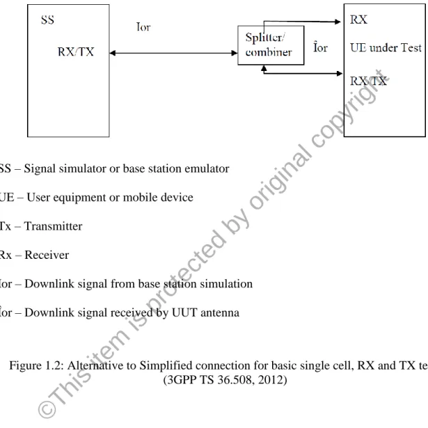
1.1 Simplified connection for basic single cell, RX and TX tests 3 1.2 Alternative to Simplified connection for basic single cell, RX and TX
tests 4
2.1 Subcarriers orthogonality of OFDM 10
2.2 Difference between OFDM and OFDMA 10
2.3 OFDMA vs SC-FDMA 11
2.4 Radio channel access mode 12
2.5 Test setup of typical LTE RF conformance cester 15 2.6 Output channel power measurement result in 5MHz from screenshot
of Agilent N9020A signal analyzer 18
2.7 Time mask measurement result from screenshot of Agilent N9020A
signal analyzer 19
2.8 Error vector magnitude test 20
2.9 Instruments required for LTE UE Tx conformance tests 21 2.10 Instruments required for LTE UE Rx conformance tests 23 2.11 Instruments required for LTE UE throughput performance
conformance tests 25
2.12 Simplified connection for basic single cell, RX and TX tests 27
2.13 Spirent SR5500 wireless channel emulator 28
2.14 Deployment of channel emulator 29
2.15 Deployment of variable gain amplifier 31
© Thi
s i tem
is pr ot ec ted by
or igi nal
c opy
right
viii
2.16 Deployment of individual ALC into the BSE 32
3.1 The flow of this research work 35
3.2 Solution with discrete components 36
3.3 Solution with details of selected components 40
3.4 GPIB connector with cable 44
3.5 Aeroflex Weinschel 3T series attenuator 44
3.6 Agilent 8762A SPDT coaxial switch 45
3.7 Agilent 84940A switch controller board 47
3.8 Main flow chart of software logic 48
3.9 Sub flow chart of software logic 49
3.10 Calibration setup to calibrate the step attenuator 52
3.11 Agilent N1914A dual channel power meter 53
3.12 Agilent E9304A power sensor 53
3.13 RF interface box 55
3.14 RF interface box in Agilent GS8800 LTE RF conformance test 56
3.15 Agilent 8494G step attenuator 41
4.1 Primary & secondary path loss differences (in low band)
without 0.5dB attenuator 59
4.2 Primary & secondary path loss differences (in low band)
with individual attenuator calibration approach 60 4.3 Primary & secondary path loss differences (in low band) 61 4.4 Primary & secondary path loss differences (in mid band) 62 4.5 Primary & secondary path loss differences (in high band) 62
© Thi
s i tem
is pr ot ec ted by
or igi nal
c opy
right
ix
4.6 Repeatability of primary & secondary path loss differences
(in low band) 63
4.7 Repeatability of primary & secondary path loss differences
(in mid band) 64
4.8 Repeatability of primary & secondary path loss differences
(in high band) 64
4.9 Reproducibility of primary & secondary path loss
differences (in low band) 65
4.10 Reproducibility of primary & secondary path loss
differences (in mid band) 66
4.11 Reproducibility of primary & secondary path loss
differences (in high band) 66
4.12 Sensitivity test results 68
© Thi
s i tem
is pr ot ec ted by
or igi nal
c opy
right
x
Metodologi Pengimbangan Tahap Antara Dua Isyarat Pautan Turun Sebelum Penerimaan Dua Antena Penerima untuk Pematuhan Ujian UE LTE
ABSTRAK
Tesis ini membentangkan metodologi alternatif sambil penjimatan kos untuk menyelesaikan isu kepada pengimbangan tahap antara dua isyarat pautan turun sebelum penerimaan dua antena penerima untuk pematuhan ujian peralatan pengguna (UE) LTE.
LTE, Long Term Evolution diiktiraf sebagai 4G kepada piawai wayarles dalam komersial.
Tetapi dalam perspektif industri, LTE dipanggil sebagai 3.9G kerana LTE tidak mengandungi keperluan 4G sepenuhnya. LTE juga bersaing dengan Worldwide Interoperability for Microwave Access (WiMAX). Oleh kerana LTE diperkenalkan 1-2 tahun kemudian, ia mempunyai kelebihan berbanding dengan WiMAX. LTE juga bertujuan untuk selular termasuk suara dan data. Jadi, penggunaan LTE adalah lebih popular. Dalam spesifikasi ujian RF kepada UE LTE, iaitu 3GPP TS 36,521-1, ia terutamanya terdiri daripada dua bahagian iaitu ujian prestasi (termasuk persediaan, gambar rajah sambungan ujian dan prosedur) bagi pemancar (Tx) dan penerima (Rx).
Penerima LTE memerlukan 2 antena penerima. Cabaran untuk pematuhan spesifikasi iaitu isyarat pautan turun selepas perpecahan perlu dijadikan tahap yang sama sebelum diterima oleh kedua-dua antena penerima UE. Ini adalah penting kepada ujian penerima UUT. Selepas perpecahan isyarat pautan turun, tahap isyarat yang melalui laluan utama (ke arah antena Rx / Tx) dan laluan kedua (ke arah antenna Rx kedua) tidak akan sama kerana lebih banyak komponen disambungkan di sepanjang laluan utama untuk menyokong ujian pemancar dan penerima, jadi ia perlu diselesaikan untuk menjadikan tahap yang sama bagi kedua-dua laluan itu. Alat emulasi saluran RF boleh digunakan untuk menyelesaikan cabaran ini kerana keupayaannya. Pengguna boleh menggunakan fungsi alat ini untuk menentukan tahap diingini untuk mengimbangi kedua-dua keluaran pautan turun dari alat emulasi. Tetapi cara ini terlalu mahal dan juga kurang digunakan jika ujian penerima biasa hanya diperlukan. Jadi, penyelesaian yang dicadangkan untuk mengimbangi laluan kedua sebagai laluan utama dengan komponen tambahan di laluan kedua yang dihubungkan dengan RX antena UE yang kedua. Tujuan ini adalah untuk mengimbangi kehilangan di antara kedua-dua laluan selepas perpecahan. Dengan itu, tahap kedua-dua isyarat pautan turun sepanjang kedua-dua laluan akan dijadi sama.
Pelemah yang boleh atur cara dijadikan komponen penting digunakan dalam cara ini kerana keupayaan diprogramkan untuk menyesuaikan pengecilan yang diperlukan.
Keseluruhan operasi ini adalah automatik dengan algoritma perisian untuk menetapkan pelemahan tambahan yang betul di sepanjang laluan kedua supaya tahapnya akan diimbangi sebagai tahap pengecilan laluan utama. Perbezaan terburuk antara laluan utama dan kedua dengan metodologi ini adalah 0.2dB. Cara ini bukan cara yang sempurna dengan perbezaan ini. Jadi, penyelesaian ini tidak setepat metodologi yang memakai alat emulasi saluran RF. 0.2dB ini akan dijadikan sebagai ketidakpastian untuk pengukuran keseluruhan. Dengan pertimbangan di antara kos dan prestasi, metodologi ini masih boleh memenuhi piawai 3GPP 36.521-1, iaitu tidak melebihi 0.7dB untuk pengukuran ketidakpastian.
© Thi
s i tem
is pr ot ec ted by
or igi nal
c opy
right
xi
Dual Downlink Signals Level Balancing Methodology Before reception of Dual Receiver Antennas for LTE UE Test Conformance
ABSTRACT
This thesis presents alternative and more significant cost save approach to resolve the dual downlink signal level balancing issue before reception of dual receiver antennas for LTE user equipment (UE) test conformance. LTE, the Long Term Evolution became common acronyms. LTE is recognized in commercial as 4G wireless cellular technology standard.
But in industry perspective, LTE is called as 3.9G because LTE is not fully up to the requirement of 4G. LTE competes with another wireless technology which is Worldwide Interoperability for Microwave Access (WiMAX). Due to LTE was introduced 1-2 years later, it has slight more significant advance compare to WiMAX. LTE is also meant for cellular which includes voice and data rather than only data. So, deployment of LTE is more popular. In the LTE UE RF test specification, 3GPP TS 36.521-1, it mainly consists two sections which are performance tests (includes setups, test connection diagrams and procedures) of transmitter (Tx) and receiver (Rx). Receiver of LTE compulsory requires 2 receiver antennas for diversity. The challenge for the specification conformance would be downlink signals after the split must need to be equal level before they are received by dual receiver antennas port of UE. This is particular on the UUT receiver tests. After the split of downlink signal path, the primary path (towards the Rx/ Tx antenna) and secondary path (towards the second Rx antenna) will not be equal path loss due to more components are connected along the primary path to support the transmitter and receiver tests, so it need to be resolved. RF channel emulator can be used to resolve this challenge due to its diversity capability as essential to channel emulation. User can utilize the close loop function of emulator to set desired level of the diversity dual outputs to balance both downlink outputs from the emulator. But this approach is too costly and also under utilized if the UE just want to have normal receiver tests under static propagation. So, the proposed solution would be dual path balancing with add-on attenuation along secondary path which connected to second Rx antenna of UE. The intention is to balance the loss between primary and secondary path after the split. Indirectly, the downlink signal level along each path would be equal. Programmable step attenuator is deployed for the extra attenuation due to its programmable capability for adjusting the required attenuation. The whole operation of this approach is automated with software algorithm in order to set the right extra attenuation along the secondary path to balance with primary path loss. The worst case difference between the primary and secondary antenna path with this approval would be 0.2dB instead of perfect with no difference. So, this solution is not as accurate as the approach using the channel emulator. This 0.2dB will become measurement uncertainty of the entire measurement setup. It is trade off between the cost and performance. This approach can still fulfill the standard of 3GPP 36.521-1, not to exceed 0.7dB as measurement uncertainty.
© Thi
s i tem
is pr ot ec ted by
or igi nal
c opy
right
1 CHAPTER 1
INTRODUCTION
1.1 Introduction
Long Term Evolution (LTE) is a wireless technology standard for cellular which was deployed since last couple of years. It is another generation of cellular wireless technology after 3G’s WCDMA and HSDPA. Typically, the improvement of generation to generation of this technology is more to the data rate capacity and latency. Commercially, LTE is called as 4G wireless technology. But for industry perspective, LTE is called as 3.9G because LTE is not fully up to the requirement of 4G. LTE-Advanced is supposed to be called as 4G which is evolved version of LTE, but it is not the focus in this thesis (Wikipedia, LTE Telecommunication, 2006).
The LTE standard was developed under 3rd Generation Partnership Project (3GPP) including the user equipment (UE) conformance test standard as well. LTE competes with another wireless technology which is Worldwide Interoperability for Microwave Access (WiMAX). WiMAX was started to be deployed 1-2 years earlier than LTE. WiMAX is intentionally for data rather than cellular. WiMAX standard was developed by members of WiMAX Forum which is different standard organization than 3GPP. Due to LTE was introduced 1-2 years later, and it has slight more significant advance compare to WiMAX (Wikipedia, LTE Telecommunication, 2006). And LTE is also meant for cellular which includes voice and data rather than only data, deployment of LTE is more popular.
© Thi
s i tem
is pr ot ec ted by
or igi nal
c opy
right
2 1.2 LTE Performance Tests
There are two standards or specifications for the LTE test solution vendors, i.e. 3GPP TS 36.521-1 for UE RF Test specification and 3GPP TS 36.523-1 UE Protocol Test specification. Some test vendors like Keysight (known as Agilent previously) only provides test solutions for RF rather than protocol due to the business nature and expertise. Protocol conformance is more to the software implementation within the phone chipset according to the standard.
In LTE UE RF test specification, 3GPP TS 36.521-1, it mainly consists two sections which are performance tests of transmitter (Tx) and receiver (Rx). Transmitter tests consist the performance tests of transmission power, time mask, modulation quality, spurious and so on. Receiver tests consist the performance tests of sensitivity, selectivity, blocking and so on (3GPP TS 36.521-1, 2012). In the chapter of literature review, these will be elaborated more in details.
1.3 Problem Statement
The thesis here will discuss about one of the compliance challenge in 3GPP TS 36.521- 1 UE RF Test specification. From 3GPP TS 36.101 UE specification, it is mentioned that receiver design of LTE UE or mobile device requires 2 receiver antennas (3GPP TS 36.101, 2016). For the standard RF test procedures of LTE UE, they are published in the 3GPP TS 36.521-1. The basic test setup to test the UE is shown in connection diagram as Figure 1.1.
All the diagrams are published in the 3GPP TS 36.508. The test procedures of UE transmitter and receiver are linked to the connection diagram in 3GPP TS 36.508.
© Thi
s i tem
is pr ot ec ted by
or igi nal
c opy
right
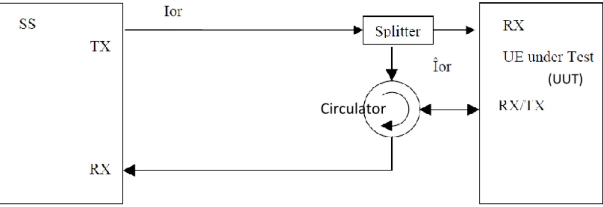
3 SS – Signal simulator or base station emulator UE – User equipment or mobile device
Tx – Transmitter Rx – Receiver
Ior – Downlink signal from base station emulator I^or – Downlink signal received by UUT antenna
Figure 1.1: Simplified connection for basic single cell, RX and TX tests (3GPP TS 36.508, 2012)
Diagram above shows the simplified test setup for fundamental test of the LTE UE transmitter and receiver. Base station emulator emulates the LTE base station with separate transmitter and receiver port. Base station will transmit the downlink signal from transmitter port towards the splitter. The splitter will split the downlink signal into two towards each receiver antenna port of UUT. The circulator is to separate the downlink and uplink signal.
The uplink signal which is transmitted from UUT will be circulated to base station receiver port. The circulator will block the uplink signal to flow towards the direction to base station transmitter port or else the uplink signal will cause signal cancellation together with the downlink. The figure 1.1 only shows the simplified test setup for the basic transmitter and receiver test.
Circulator
(UUT)
© Thi
s i tem
is pr ot ec ted by
or igi nal
c opy
right
4
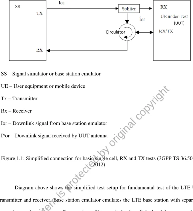
Alternatively, the test setup above can be alternatively connected as Figure 1.2. It is subjected to the design of base station emulator which must have common antenna port for transmitter and receiver.
SS – Signal simulator or base station emulator UE – User equipment or mobile device
Tx – Transmitter Rx – Receiver
Ior – Downlink signal from base station simulation Îor – Downlink signal received by UUT antenna
Figure 1.2: Alternative to Simplified connection for basic single cell, RX and TX tests (3GPP TS 36.508, 2012)
According to the LTE device test standard, 3GPP TS 36.521-1, downlink signals after the split must need to be equal in terms of amplitude or level before they are received by dual receiver antennas port of UUT. This is particular for UUT receiver tests. The downlink signal level for device receiver sensitivity test is extremely low until -100 dBm (3GPP TS 36.521- 1, 2012). The downlink source is from base station emulator (BSE). Such low level of downlink signal is to simulate the worst case scenario for sensitivity test of each receiver antenna of device. Since it is worst case scenario, the downlink signal level cannot go lower than that. So, it is important to have equal path loss between each path of the splitter output
© Thi
s i tem
is pr ot ec ted by
or igi nal
c opy
right
5
and UUT antenna. Otherwise, with offsetting the downlink output level from the BSE which consists only single downlink source, it can only compensate the loss of either one of these antenna paths rather than two paths correctly.
For the case according to the connection diagram in Figure 1.1, after the split of downlink signal path, the primary path (towards the Rx/ Tx antenna) and secondary path (towards the second Rx antenna) will not be equal path loss due to more components are connected along the primary path to support the transmitter and receiver tests. If primary and secondary path loss are different, the downlink signal level of each of these paths after split will be different as well, and then these will not be compliant according to the conformance requirement.
1.4 Objectives
The objectives of this research are:
a) To design the cost effective solution to resolve the problem on how to make both downlink signal levels be equal after the split in order to comply the standard of 3GPP TS 36.521-1.
b) To evaluate the solution with theoretical calculation and measurement data.
The motivation of this work is to come out an alternative method with significant cost effective to resolve the challenge of making both downlink signal levels be equal after the split in order for conformance purpose. The contribution is significant to the LTE test conformance industry. If no such idea of alternative approach, the existing one would be multiple time more expensive and cause higher test cost on LTE device. As a result, this will either cause less profit margin to the manufacturer, or cause the selling price of LTE device become more expensive.
© Thi
s i tem
is pr ot ec ted by
or igi nal
c opy
right
6 1.5 Organization of Thesis
This thesis contains 5 chapters.
Chapter 1 will provide a brief introduction to LTE and its 3GPP standard specification.
It will also discuss about the problem or challenged for complying the specification, which will become the problem statement of this thesis for resolution.
Chapter 2 will discuss about the existing available solution. And it will also discuss about the deployment challenge of each of the solution.
Chapter 3 will discuss about the proposed solution. From the proposed solution, it will be extracted until component level and discuss about the details of each deployed component.
Besides, this chapter will also discuss about the software logic.
Chapter 4 will analyze the collected data or results from the proposed solution. And it also discuss about the experimental data to compare couple of different flow of the software logic for decision which to deploy.
Chapter 5 will conclude the thesis according to the result analysis of previous chapter.
And it will also suggest certain area for future improvement purpose.
© Thi
s i tem
is pr ot ec ted by
or igi nal
c opy
right
7 CHAPTER 2
LITERATURE REVIEW
According to the problem statement which was discussed in previous chapter, the research topic is to resolve the problem of making both downlink signal levels be equal after the split. The equal signal levels are the requirement for LTE RF conformance tester to fully comply to the standard of 3GPP TS 36.521-1 (3GPP TS 36.521-1, 2012). The first sub chapter as below will discuss about LTE and then WiMAX. Then, the subsequent sub chapter will discuss about the conformance test of LTE user equipment (UE) and the important to resolve this problem statement. And the following sub chapter will discuss about the existing test method to handle the dual downlink antenna of UE.
2.1 Overview of LTE
LTE, the Long Term Evolution is one of the latest wireless technology standard for cellular deployment since last couple years. It is another generation of wireless technology comparing with 3G of WCDMA and HSDPA. Typically, the technical performance improvement of the following generation is more to the data rate capacity and latency. The enhancement from LTE is as below (Rumney, 2013) (Sesia, 2013).
• reduced delays, in terms of both connection establishment (<100ms) and transmission latency (<10ms);
• increased user data rates with peak data rates up to >100Mbps for downlink and
>50Mbps for uplink ;
• increased cell-edge bit-rate, for uniformity of service provision;
© Thi
s i tem
is pr ot ec ted by
or igi nal
c opy
right
8
• reduced cost per bit, implying improved spectral efficiency over 3G HSPA with 3 to 4 times in downlink and 2 to 3 times in uplink;
• greater flexibility of spectrum usage, in both new and pre-existing bands with scalable channel bandwidths of 1.4MHz, 3MHz, 5MHz, 10MHz, 15MHz and 20MHz in both downlink and uplink;
• simplified network architecture;
• seamless mobility, including between different radio-access technologies;
• reasonable power consumption for the mobile terminal.
Commercially, LTE is called as 4G wireless technology for cellular in terms of voice and data. 2G cellular technology would be GSM (Global System for Mobile communication) for voice and GPRS (General Packet Radio Service)/ EDGE (Enhanced Data rates for GSM Evolution) for data. Then 3G would be WCDMA (Wideband Code Division Multiple Access) for voice and HSPA (High Speed Packet Access)/ HSPA+ for data. For those in industry, they call LTE as 3.9G because LTE is not up to the requirement of 4G. Only LTE-Advanced is called as 4G which is evolved version of LTE (Abdullah et al., 2011). The requirements of LTE-Advanced are defined as below (Rumney, 2013).
• Peak data rate: 1Gbps for downlink, 500Mbps for uplink;
• Latency: idle to be connected <50ms;
• Spectral efficiency: 2 times for downlink, 3 to 4 times for uplink
• Mobility: support up to 350 km/h and some frequency bands 500 km/h
LTE-Advanced is still in the stage of pre-deployment, and it is not the focus in this thesis.
© Thi
s i tem
is pr ot ec ted by
or igi nal
c opy
right
9 2.2 Overview of WiMAX
WiMAX (Worldwide Interoperability for Microwave Access) is also another wireless technology to address higher data rates which is close similar to LTE. WiMAX was actually introduced and deployed couple years earlier than LTE. It is kind of “competitor” relationship to describe LTE vs WiMAX. LTE standard was defined by 3GPP (3rd Generation Partnership Project) and WiMAX standard was defined by WiMAX Forum group under IEEE (Institute of Electrical & Electronics Engineers) from North America (Korowajczuk, 2011).
WiMAX is not meant for cellular deployment. This is due to IEEE is not standardization body to address the cellular issue. So, WiMAX would not exist in any cellular device which need to deploy the cellular network. WiMAX, which IEEE 802.16e as the standard is kind of next generation of WLAN (Wireless LAN) or WiFi which IEEE 802.11a/b/g as standard. So, WiMAX is another choice for wireless online user which can have better experience in terms of handling higher data rates during that time before the exist of LTE .
2.3 Technical Overview of LTE vs WiMAX
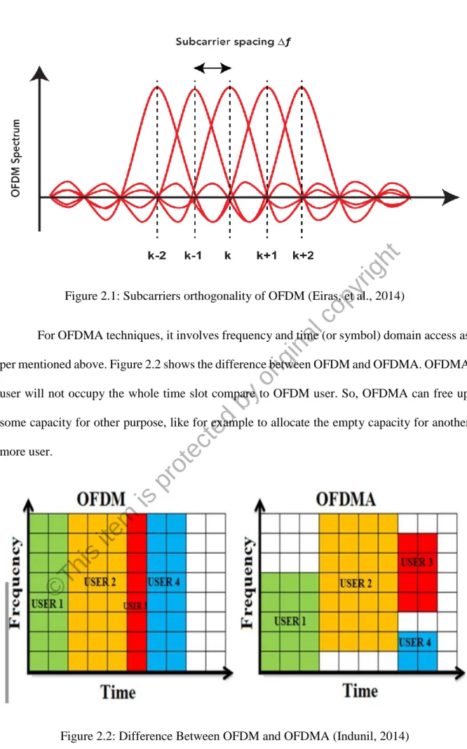
Some similar techniques are deployed between LTE and WiMAX. Such as modulation scheme, WiMAX and LTE downlink deploy the same which is OFDMA (Orthogonal Frequency Division Multiple Access). OFDMA is the multiple access version of OFDM (Orthogonal Frequency Division Multiplexing) which involves frequency domain and time domain for multiple access purpose to carry the data. OFDM only involve frequency domain.
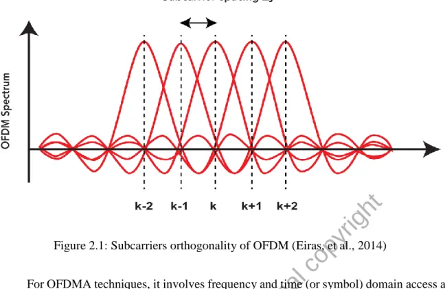
Data is transmitted on multiple subcarriers for each symbol as Fig 2.1. Subcarriers are spaced so that all other subcarriers have nulls at each subcarrier peak. This create orthogonal of the subcarriers, so each subcarrier will not interfere each other. OFDM creates less susceptible to narrowband interference and multipath. (Cho, Kim, Yang, Kang, 2010)
© Thi
s i tem
is pr ot ec ted by
or igi nal
c opy
right
10
Figure 2.1: Subcarriers orthogonality of OFDM (Eiras, et al., 2014)
For OFDMA techniques, it involves frequency and time (or symbol) domain access as per mentioned above. Figure 2.2 shows the difference between OFDM and OFDMA. OFDMA user will not occupy the whole time slot compare to OFDM user. So, OFDMA can free up some capacity for other purpose, like for example to allocate the empty capacity for another more user.
Figure 2.2: Difference Between OFDM and OFDMA (Indunil, 2014)
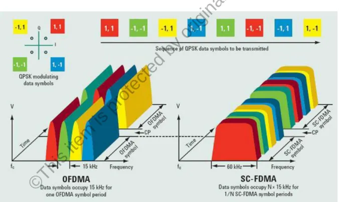
For LTE uplink, it deploys SC-FDMA (Single Carrier Frequency Division Multiple Access) rather than OFDMA. It is unlike WiMAX which both downlink and uplink also
© Thi
s i tem
is pr ot ec ted by
or igi nal
c opy
right
11
deploys OFDMA. The high peak-to-average power ratio (PAPR) associated with OFDM led 3GPP to look for an alternative modulation scheme for LTE uplink (Rumney, 2013). Uplink definitely has concern on the high PAPR due to uplink carries the high amplitude signal. SC- FDMA was chosen due to its low PAPR techniques of single carrier transmission system (Cho, Kim, Yang, Kang, 2010). It also has flexible frequency of OFDMA.
From the Fig 2.3, the most obvious difference between OFDMA vs SC-FDMA is that OFDMA transmits four QPSK data symbols in parallel, while SC-FDMA transmits the four QPSK data symbols in series at 4 times the rate, with each symbol occupied a wider bandwidth. So, with this way, SC-FDMA turns around the undesirable high PAPR caused by OFDMA to avoid parallel transmission of multi symbols that creates the high PAPR concern.
Figure 2.3: OFDMA vs SC-FDMA (Rumney, 2013)
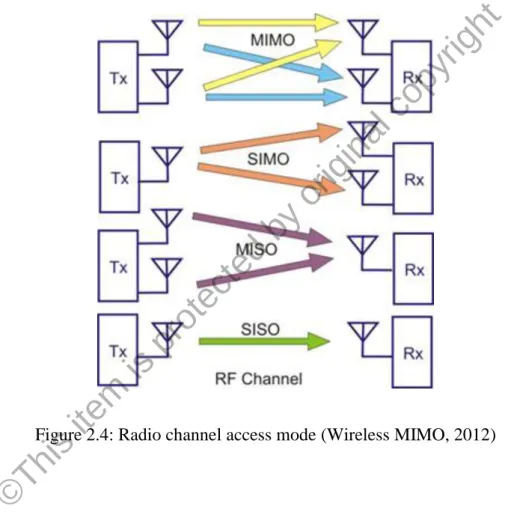
For the antenna, LTE and WiMAX deploy similar technique which is MIMO (multiple input multiple output). MIMO capability provides flexible radio channel access mode according to the Fig 2.4. The change of each mode depends on the required situation. For normal transmission and reception between Tx (normally it is base station) and Rx (normally it is cellular device), SISO (single input and single output) is more than enough to handle it.
© Thi
s i tem
is pr ot ec ted by
or igi nal
c opy
right
12
For SIMO (single input multiple output) or also known as receive diversity, its diversity reception capability is suited and robust to low signal-to-noise ratio (SNR) conditions, such as fading during receiving. Then for MISO (multiple input single output) or known as transmit diversity, it is the other way round compare to SIMO, which is suited and robust during transmitting in fading condition. For MIMO, it is not only robust for low SNR condition, it can also increase the data rates due to multiple data streams rather than single data stream can be transmitted simultaneously (Huang, Papadias, 2012).
Figure 2.4: Radio channel access mode (Wireless MIMO, 2012)
Although WiMAX was introduced slight earlier than LTE, WiMAX deployment is not as common as LTE. LTE can perform better in term of requirement definitions or specifications as mentioned in the sub chapter above. Further more, LTE can be deployed thru the upgrade of the 3G UMTS (Universal Mobile Telecommunication System) network system.
With the possibility to leverage from 3G system for upgrade to LTE , rather than to install with another fully new network system, LTE definitely is in more advantage situation compare to WiMAX.
© Thi
s i tem
is pr ot ec ted by
or igi nal
c opy
right