Moreover, the ONU deployment can be made closer to the users in the FTTB solution. It should be noted that there are several RoF options that can be employed in the network.
Introduction
Fog computing provides the basic platform for deploying cyber-physical system (CPS) applications that require ultra-low latency. Therefore, an Optical-Fog layer is introduced to provide a new, secure, highly distributed and ultra-dense fog computing infrastructure. Therefore, an EEG-based VR framework is also introduced that uses the resources of the optical network in the cloud/fog computing environment.
Fog computing is a new distributed architecture that brings computing, storage and network services closer to the end user [3]. The integration of fog computing and PON is a cheap, scalable and simple technology that provides a very promising solution for building e-learning based smart educational applications [5]. Utilization of optical resources in cloud/fog computing environment In order to handle real-time and bandwidth-intensive applications, the fog utilizes.
Utilization of optical resources in cloud/fog computing environment In order to handle real-time and bandwidth-intensive applications, fog leverages
SDN-based optical network
As shown in Figure 2, it provides a more programmatic and abstract view of the underlying optical network through the northbound interface [10]. To handle real-time, bandwidth-intensive applications, fog uses the computing resources of the SDN-based optical network. In PON network, OLT uses time division multiplexing access (TDMA) which provides the share of the upstream channel between.
Here, the OLT and all connected ONUs are well synchronized, resulting in collision-free transmission of the traffic or data frames. If a malicious ONU intends to send data frames outside its pre-allocated time slot, the collision may encounter data frames from other ONUs, degrading the quality of service (QoS) of the optical channel. It provides ultra-low latency and less energy consumption for IoT devices and uses the majority of the optical layer computing resources rather than the cloud layer.
OpticalFogNode for implementing CPS system
To handle real-time processing, this layer uses the optical network resources by creating OpticalFogNode. All free available resources (FARs) of the optical elements are grouped together to form an OpticalFogNode with the computing capabilities such as processor, memory and bandwidth. ONV converts the free available physical resources of the optical network elements into the virtual resources as infrastructure-as-a-service (IaaS) model.
In an optical network in a 5G environment, the OpticalFogNode has a flow table that is used to match the routing information of the received packet along the way. Thus, a new entry is added (when a path is selected) in the OpticalFogNode flow table for incoming future packets. For the design of virtual infrastructure, a concept of freely available resources is proposed, which uses freely available resources of optical network elements lying on the Optical-Fog layer.
EEG-based VR gaming applications
It helps to find the shortest path with least congestion by using the historical knowledge of the connection to node c and the waiting time of packets to c in node n's queue. To find the shortest path with least congestion, the node with minimum delivery cost is selected as shown in Figure 7. 1 − Θ nc (t)] + C nc (t − 1) (3) The shortest path with least congestion is identified by pulling packets against the neighbors who have the smallest queue.
An algorithm using Edge-Fog layer and Optical-Fog layer in Optical-Fog network is proposed to introduce game modules. The deployable modules for each fog device in the ε d Edge ∪ d Optical path are identified by calculating the processing requirement against the available capacity of the fog devices. The M module is installed on a dEdge or dOptical fog machine only if all other modules are already installed in the bottom-up path.
Performance analysis
Latency measure
Energy consumption analysis
Bandwidth measure
Conclusion
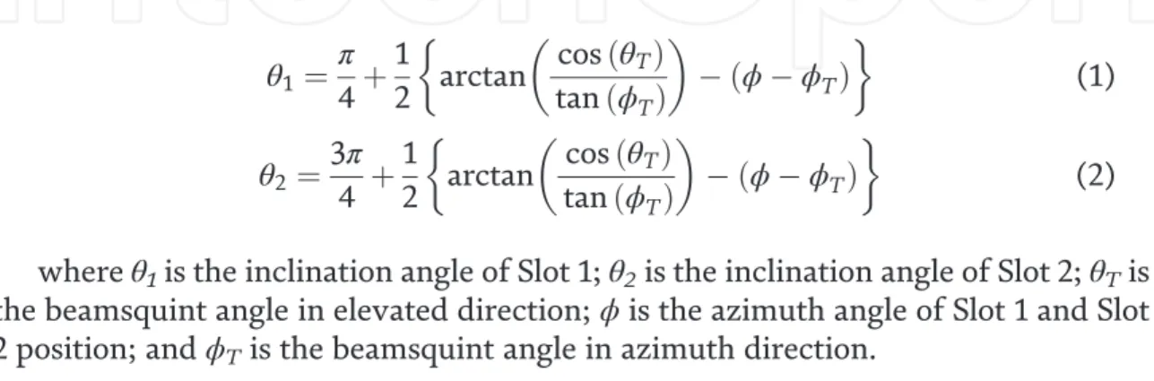
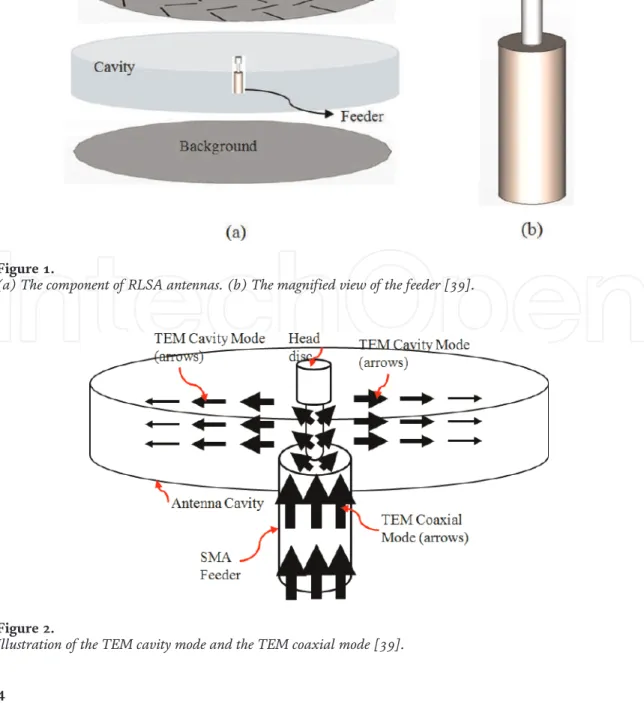
This chapter briefly discusses all about radial line slot array (RLSA) antennas, especially linearly polarized (LP)-RLSA antennas. We hope that the ideas can inspire research for the next development of RLSA antennas. Ando also proposed the beamsquint technique to improve the poor reflection coefficient in linearly polarized RLSA antennas [2, 3].
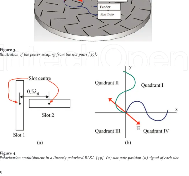
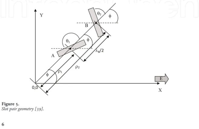
Bialkowski and Zagriatski investigated the design of RLSA antennas for wireless LANs and successfully fabricated a 2.4/5.2 GHz dual-band antenna [ 27 , 28 ]. The feeder is a part of RLSA antennas used to feed signals from a transmission line to the antenna. The pair of slots must be placed in the correct position on the radiating surface of the RLSA antennas.
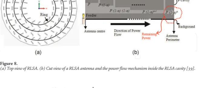
The length of the slots on the radiating surface of the RLSA antennas must be varied to achieve uniform aperture illumination. This is due to the drawing of RLSA antenna slots, which are difficult to do without the use of computer programs.
Summary
Key components of the power system must be continuously monitored and protected to maintain the quality and reliability of the power source. The new feature of this work is the adjustment of the membership function as an inverse mechanism derived from the Fuzzy Logic Controller. In conclusion, our main objective in this chapter is to develop solutions to improve distributed power propagation and high-speed synchronization communication, which is essential for the continued development of the smart grid field.
As a result, the performance of the existing distribution network's traditional inverse time protection system was evaluated. This chapter introduces the transformation of the traditional protection strategy to the future intelligent distribution grid protection system. The proposed intelligent protection system aims to reduce the time to eliminate faults, to ensure the selectivity of protection and to increase the availability of GD's devices during faults.
Introduction
In this way, we have identified the problems faced by currently valid protection strategies; The simulation results prove that the traditional protection system is not sufficient to ensure a satisfactory protection selectivity. An intelligent algorithm ensures the selectivity of the protection by minimizing the failure time and eliminating the problem of large disconnection time in the system [1]. The reliable real-time flow of information between parts of the network is critical to the success of the smart grid self-regulation process.
One of the most popular technologies is ZigBee wireless sensor network (WSN), which is distributed on the smart network structure, which has many devices to communicate with each other through the wireless network. Sensors are devices that can recognize various of the physical units such as current, voltage, impedance, etc. The construction of this chapter is as follows: Section 2 gives a study of the SG communication system.
The smart grid communication network architecture
Wireless area network (WAN)
It can help prevent power outages by providing real-time information from the power grid.
Network home area (HAN)
Neighbourhood area network (NAN)
Proposed protection system simulation and modelling
The adaptive neuro-fuzzy approach
The system is exported to the desired state of the control action can be described by the concept of the well-known "if-then". The linguistic form of the control rules forms the basis of the designed fuzzy unit. It depends on the accuracy of the choice of parameters, which is the translation of the linguistic rules of fuzzy set theory.
The neural network has two inputs, e(t) and Δe(t), and the neural network signal output α, which is used to fine-tune the operator product control. We have chosen fuzzy set and membership functions, Table 1 summarizes the development of the rules used in this study [1]. Formation of a neural network consisting of three layers (two input layers, three hidden layers and one output layer).
Simulation results
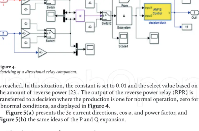
The structure of the proposed protection is shown in Figure 4. The nodes of in_1 and in_2 represent the input variables and send their values to the blocks containing the respective member functions of the Neuro-Fuzzy controller. In this case, the mechanical power input from the generator deviates within 1-2 seconds from 0.6 to 0.7 pu, under normal circumstances the observed condition is shown in Figure 10 and the relay does not trip. The relay reacts to this change after 0.15 seconds for safe and the relay trips where the fault occurred after 2 seconds as shown in Figure 11.
The reverse current adjustment knob and delay time are shown in table A2 of the appendix, then the trip is confirmed with the minimum reverse current in the range of 2-20%. The switch-off delay setting range is 0–20 seconds. a) Input-output power performance; and (b) relay status.
Wireless sensor network using OPNET simulator 1 Zigbee network method
Simulation results
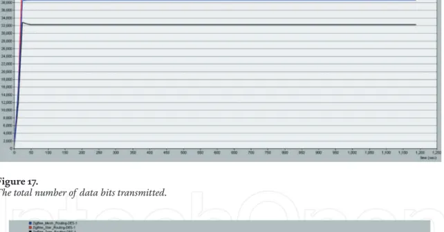
The steady-state results for the star, mesh and tree topologies are and 0.028 Mbit/s. In the star topology, maximum throughput can be achieved, this finding is that the star topology interacts with the PAN (Personal Area Network) coordinator. (Figure 16). As shown in Figure 17, and findings indicate that the maximum data traffic is in a star topology because this topology type allows communication with the coordinator. This discovery means that the traffic received in the star topology is the largest because all devices communicate through the PAN coordinator and are responsible for generating traffic and routing [1].
And the delay time of mesh/tree topology is longer than that of star topology, as shown in Figure 19. As shown in Figure 20, MACload is used to forward the load for each PAN when transmitting packets in IEEE 802.15. .4 MAC, that is the physical layer, in the upper layers. As shown in Table 2, the local route information only covers a small area (the diameter of the test distance is about 250 meters) [1].
Conclusions
The star topology is the best in terms of performance and has a MAC load that is similar to the mesh topology. Since the ZigBee network has a large number of nodes, so the use of star topology is considered to be very important. The author would like to thank the editors and reviewers for their constructive comments and suggestions.
Sandra Maljavac and all the staff who have worked with you and I wish you all the best.
Appendix
This chapter is distributed under the terms of the Creative Commons Attribution License (http://creativecommons.org/licenses/ . by/3.0), which permits unrestricted use, distribution, and reproduction in any media, provided the original work is properly cited. A new protection method to prevent reverse current flow based on neurofuzzy network for smart grid. Wireless Sensor Networks: A Survey of the State of the Art and the 802.15.4 and ZigBee Standards.
High-efficiency remote control system and intelligent street lighting using a network of ZigBee devices and sensors. A Smart City application: A fully controlled street lighting island based on the raspberry-pi card, a ZigBee and WiMAX sensor network. A differential busbar protection based on fuzzy reasoning system and Rogowski-spiral current sensor for microgrid.