EXPERIMENTAL STUDY (COMPARISON) OF ENGINE
RUBBER MOUNTING’s VIBRATION
This report submitted in accordance with requirement of the Universiti Teknikal Malaysia Melaka (UTeM) for the Bachelor of Engineering Technology in Mechanical (Automotive) with Honour
by
MUHAMMAD HIJLAL B. JAMALULIL
B071210527
920730-05-5583
SUPERVISED BY :
EN. ADNAN BIN KATIJAN
FACULTY OF ENGINEERING TECHNOLOGY UNIVERSITI TEKNIKAL MALAYSIA MELAKA (UTeM)
i
ABSTRAK
Projek Tahun Akhir Sarjana Muda saya memfokuskan akan kajian dan perbandingan terhadap 3 jenis ‘mount’ , menguji setiap jenis ‘mount’ ke atas gegaran yang dihasilkan oleh enjin kereta Proton SAGA pada RPM enjin yang berlainan kelajuan torque ( pada gear neutral). Secara asasnya, kajian lebih terarah dan memfokuskan tentang ciri dan kriteria utama akan sebuah unit enjin ‘mount’ untuk mengatasi jumlah getaran yang akan diserap. Setiap unit yang berjenis getah akan dilengkapi dengan set ujian pada mesin diagnostik getaran pada setiap satu ‘mount’ yang akan diuji.
Bagi tujuan menjalankan proses eksperimentasi, ianya akan dikendalikan ke atas kereta jenis Proton SAGA 1.3. Set lengkap ‘vibration sensor meter’ akan digunakan terhadap 4 bahagian
bagi setiap set ‘rubber mounting’ bagi mengambil bacaan getaran yang diterima daripada
enjin. Uji kaji ini akan dijalankan di Makmal Diagnostik Getaran, Fakulti Teknologi Kejuruteraan UTeM.
Kajian projek ini juga termasuk kajian dan aspek asas keseluruhan enjin getah pelekap ‘engine rubber mount’ seperti tujuan, fungsi utama , pengukuran dimensi luaran, ciri-ciri
ii
ABSTRACT
My final year project was focused and specified on study and research on 3 different type of engine rubber mounting,at which to study the important aspect criteria of the engine mount that can overcome the vibration at its best when testing on different stage of engine RPM while in idle state. Basically, the 3 different type of engine rubber mounting will be tested each one of them with Proton SAGA engine using MDG Vibration Test Machine. All the specified data and result were collected and analyzed to determine which type of engine rubber mounting tested would produce the least or minimum vibration produce while revving the engine at different RPM level.
For experiment purposed, full research will be done on engine mounting system in Proton SAGA, which was selected to be the experimenntal subject vehicle. So, during the experiment held 1 unit of complete set sensor from MDG Vibration Test Machine will be set placed in every mounting point in the MDG Laboratory, Makmal Diagnostik Getaran, Fakulti Teknologi Kejuruteraan UTeM.
iii
APPROVAL
This report is submitted to the Faculty of Engineering Technology of UTeM as a partial fulfillment of the requirements for the degree of Bachelor of Engineering Technology (Bachelor’s Degree of Engineering Technology in Mechanical (Automotive) with Hons.). The member of the supervisory is as follow:
iv
DECLARATION
I declared that this report is my own writing except the paragragph that stated and declared as reference of original source.
Writer’s Name
...
Signature
...
Date
v
DEDICATION
vi
ACKNOWLEDGEMENT
First of all, I would like to thank Allah SWT for giving me strength and time to complete this project successfully. Then, I would like to express my deepest gratitude to my project supervisor, Encik Adnan Bin Katijan who had continuously giving me guidance, ideas and support for this project. It would be difficult to complete this project without his support,help and misunderstanding.
I also would like to express the deepest appreciation to the lecturers and staff member of Faculty of Engineering Technology ,UTeM which involve directly or indirectly on conduct and assisting me to finish this project completely. Their cooperation indeed too make my work become easier and faster. Big thanks to everyone involve.
vii
LITERATURE REVIEW ... Error! Bookmark not defined. 2.1 Main Purpose of Engine Rubber Mounting ... 7
2.2 Design & basic concept for engine mount ... 9
2.4 Source of Vibration in Vehicle ... Error! Bookmark not defined. 2.3 Properties of Engine Rubber Mounting ... 16
2.3.1 Performance Limitations of Engine Mount ... 16
2.3.2 Strength & Durability of an Engine Mount... 17
METHODOLOGY ... 21
3.1 Introduction ... 21
3.2 Project Flow Chart ... 22
3.3 Experimental Planning Progress & Equipment ... 23
3.4 Selected Position r Sensor Point on Engine Mount ... 26
viii
RESULT & DISCUSSION ... 29
4.1 Result & Data Collection ... 29
4.2 Engine Rubber Mounting Dimension Data ... 30
4.3 Vibration Vertical Displacement Result ... 34
4.4 Vibration Impact Analysis on Engine ... 38
4.5 Effect of Rubber Mount Part A,B,C & D to Engine’s Vibration ... 40
CONCLUSION ... 41
5.1 Experiment Summary ... 41
5.2 Recomendation for Engine Mount Future Development ... 42
1 engine mounting vibration impact on 3 different type of engine rubber mounting. The purpose of this case study is to find out the best engine mounting out of 3 choice that produce the least or minimum vibration on engine mounting system.
In experiment methods that have been done,MDG Vibration Test Machine with sensitivity 197 mV/g is used to collect vibration characteristic on certain condition while revving the engine RPM at different stage. All the data collected with sensor for the machine is in analog signal, then this signal will display and presented in graphical output which later to be compared all the basic concept for each engine rubber mounting that related with the vibration produce.
2 1.2OBJECTIVE OF STUDY
Main objective of this research is to gather vibration amplitude result and data on selected rubber engine mount unit by experiment test. This vibration generates by engine and gearbox unit will be transfer to the Proton SAGA chassis via engine and gearbox mounting system.
The goal of the research is to:
a. To compare the 3 different set of engine mount on the value of vibration analysis obtain from the experiment test.
3
1.3PROBLEM STATEMENT
For over 100 years, comfort in road vehicles has been linked to the introduction of passive components that isolate passenger compartments from mechanical vibration. Near-optimal performance has been achieved by years of experimentation and testing, careful selection and shaping of individual component characteristics, and the development of ingenious mechanisms intended to minimize the effect of inherent design constraints associated with passive systems.
The vehicle engine mount system, generally, consists of an engine (vibration source) and several mounts connected to the vehicle structure.Hence, engine rubber mount must be stiff enough to hold the engine and part of gear box , which at the same time soft at its optimal to absorb vibration and critical movement. Also, engine mount must be flexible enough to permit frame to twist.
Since engine rubber mounting are responsible for holding the engine in its compartment place during the vibration and engine torque takes place to overcome the vibration disturbance,the experiment conducted with 3 different type of engine rubber mounting hence, which are the best engine rubber mounting out of the 3 type tested that can overcome the least vibration impact (best requirement for engine rubber mounting to overcome vibration from engine & gear-box)
Engine vibrations have been one of the major problems for the engine manufacturers in
the world. The engine excitation forces, arising from the gas pressure and unbalance forces are the sources of vibrations in the engine. Therefore, different kinds of engine mount systems from elastomeric to hydraulic, from passive to active have been developed to improve the mount
performance.
4 1.4 WORKSCOPE
For this research, it will be focused to study how vibration originated from engine and gearbox unit will be transmit to the engine rubber mounting. As we noticed, the only physical connection between engine and gearbox unit to vehicle chassis is mounting system. Common practice in the automotive industry is to apply passive mounting system due to the low cost. Basic design of passive mounting system will be study by revving the engine until reach the different RPM/ torque at idle static state.
5 engine produces broad band vibration resulting from combustion processes. The engine driven accessories and the transmission generate vibration as a result of their unbalances. The tires and suspension generate vibration as a result of tire tread interaction with the road surface. Wind noise results from viscous shearing in the boundary layer of air surrounding the vehicle. However, this research is more focused on chassis vibration induce by engine and power transmission component especially vibration that causes from unbalanced rotating mass.
Previous research held by other party including researcher from School of Automotive Engineering, University of Ulsan, Tokyo Institute of Technology, and Massachusetts Institute of Technology (MIT) are more focused on the designing new engine mounting system controlled by hydraulic and actuator. Some of them are focused on the automotive noise and vibration for the whole of the vehicle and not specifically on the engine mounting.
In research conducted by Kyong Kwan Ahn from School of Automotive Engineering, University of Ulsan, he and his team conducted a research on isolation of vibration related engine by hydraulic engine mount with controllable area of inertia track.
6
Itsuro Kajiwara and Akio Nagamatsu from Tokyo institute of Technology, Japan investigated the active and adaptive control of engine mounting as a way to overcoming the weakness of passive engine mounting. Their research covered mathematic formulation of active engine mounting and engine mount control design.
Lisa A. Sievers and Andreas H. Flotow from Department of Aeronautics and Astronautics study on active control of engine mount to enhance the quality of passenger compartment in the term of comfort. They also proposed three control schemes for actively controlling engine mounts.
7
2.1 Main Purpose of Engine Rubber Mounting
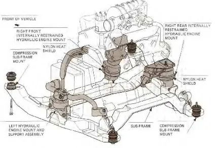
For this research, the main function of the engine and gearbox mounting system has been investigated thoroughly. The basic design, the main function of this mounting is to:
a. to attached engine and gearbox unit to the vehicle chassis b. to absorb engine noise and vibration
c. to prevent vibration from reaching radiator, electronic control and any vital parts d. isolating engine and transmission from the chassis
Engine mounts must be stiff enough to hold the engine and gearbox, and at the same time soft to absorb vibration. Also engine mounts must be flexible to permit frame to twist.
In practice, most of the manufacturer usually attached the engine and gearbox to the chassis according to the specific needs. Which axle would drive the vehicle will determine the layout of the engine and gearbox unit in the engine bay. If rear axle was selected to drive the vehicle, engine and gearbox unit will be arranged in longitudinal arrangement. But if front axle was selected, engine and gearbox unit will be arranged in transverse arrangement.
8
The Engine mount not only supports engine weight, but also attenuates the vibration and restricts excessive displacement of engine. The invalidation of rubber cushion would result in adverse effects or serious consequences in many aspects. So it's necessary to conduct research of engine mount to fmd causes of destruction, improve their structures to enhance their service life.
Plus, it is an attachment point for a part or system to the chassis. Secondly, it often acts as an isolator , keeping noise and vibration from being transferred to the driver and passengers. In some cases, it may also be an adjustment point to keep a component in proper alignment. Engine mounts properly locate the engine in the chassis, and are an important factor in how smoothly a vehicle operates. The mounts are designed to allow a certain amount of rotation, plus dampening much of the engine vibration
9
2.2 Design & basic concept for engine mount
An engine mount must satisfy two essential but conflicting criteria. First, it should be stiff and highly damped to control the idle shake and engine mounting resonance over 5±30 Hz. Also, it must be able to control, like a shock absorber, the motion resulting from quasistatic load conditions such as travel on bumpy roads, abrupt vehicle acceleration or deceleration, and braking and cornering. Second, for a small amplitude excitation over the higher frequency range, a compliant but lightly damped mount is required for vibration isolation and acoustic comfort, like a conventional rubber mount.
Resonant vibration of body panels arising from unbalanced loads existing in the engine body is intensified by frameless or unitary chassis construction. This has forced designers to direct their attention to the development of high quality engine mounting devices in order to ensure that improved comfort in riding and silencing shall not be offset by fatiguing vibration effects. An engine mount system is designed to reduce the transmission of engine vibration to the chassis. Engine mounts are used to connect a car engine to the car frame. They are usually made of rubber and metal. An engine mount must satisfy two essential but conflicting criteria. First, it should be stiff and highly damped to control the idle shake and engine mounting resonance. Also, it must be able to control, like a shock absorber, the motion resulting from load conditions such as travel on bumpy roads. Second, for a small amplitude excitation over the higher frequency range, a compliant but lightly damped mount is required for vibration isolation and passenger comfort
10
Figure below shows the type of various design that optimize the criterias of good rubber engine mount
(b) Design of Two Arm Engine Mount 1
11
(e)Design of Filler Arm Engine Mount 1 (f) Design of Four Arm Symmetry Engine 1
Figure 2.2 (a-f) : Type of engine mount design(S. Agostoni and M. Giombini, 2000)
Each of the design above has the highest natural frequency amongst all design iterations. Hence , it can be best conclude that this design is best suited as the table shown below
Table 2.2 : Table of natural frequency iterations (S. Agostoni and M. Giombini, 2000)
The analysis results which are obtained from two arm, three arm, four arm, filler arm and four arm symmetry engine mounts in which the design of four arm symmetry engine mount curve obtained follows exactly the experimental test curve and also this design has the highest natural frequency amongst all design iterations. The results indicated that the rubber used in the engine mount had increased the frequency from 1.2Hz (basic design) to 1.8Hz (four arm symmetry). As the design is changing in rubber, the mode of frequency increases and it has found that 1.8Hz is the frequency for the four arm symmetry mount design.
-R Singh “Dynamic design of automotive systems: Engine mounts and structural joints” Department of Mechanical Engineering, Ohio State University, Columbus, OH 43210, Journal of Automobile
Engineering Volume 24,
12 2.2.1 Mount Requirement and Type
An engine mount must satisfy two essential but conflicting criteria. First, it should be stiff and highly damped to control the idle shake and engine mounting resonance. Also, it must be able to control, like a shock absorber, the motion resulting from load conditions such as travel on bumpy roads. Second, for a small amplitude excitation over the higher frequency range, a compliant but lightly damped mount is required for vibration isolation and passenger comfort. A good engine mount essentially required thise two criterias which were a low spring rate and high damping during idling and a high spring rate and low damping for high speeds, manoeuvring and when traversing rough terrains.
N. G. Negrete, J. Vinolas. Journal of Applied Mechanics, vol. 76, Jan. 2009
2.2.2 Type of Engine Mount
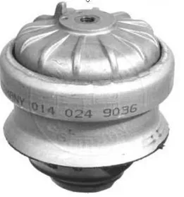
i. Simple Rubber Engine Mounts
– These are the least costly and least effective forms of mount and clearly do not meet all the conflicting requirements.
– They do not provide the high levels of damping required at idling speeds
– Such a weight reduction and increased power requirements often have adverse effects on vibratory behavior, greatly increasing the vibration and noise level
13
ii. Hydro-elastic mounts
– These generally contain two elastic reservoirs filled with a hydraulic fluid. – Some also contain a gas filled reservoir.
– This type of mount exploits the feature of mass-augmented dynamic damping which is a form of tuned vibration absorber.
– In operation there is relative motion across the damper which produces flexure of the rubber component and transfer of fluid between chambers, thereby inducing a change in mount transmissibility.
– This type of mount has become common in recent years and also in high marketing industry.
(Kim et al., 1992; Muller et al., 1996).
14
iii. Semi-Active Mount
– The operation of these mounts is dependent on modifying the magnitude of the forces transmitted through coupling devices.
– They may be implemented via low-bandwidth low power actuators which are suited to open-loop control.
– Some forms of hydraulic semi-active (adaptive) mount use low powered actuators to induce changes in mount properties by modifying the hydraulic parameters within the mount.
– The actuators may then be on–off (adaptive) or continously variable (semi-active) types. – Semi-active control mechanism ( Hydraulic type )
– Considerable effort has been devoted to this type of technology in recent years.
15
iv. Active Engine Mount
– This type of mount requires control of both the magnitude and direction of the actuator force used to adjust the coupling device.
– High-speed actuators and sensors require having an operating bandwidth to match the frequency spectrum of the disturbance.
–Act as classical- hydraulic mount, and an electromagnetic actuator to isolate high frequency vibration
– Power consumption is generally high in order to satisfy the response criteria. – Active vibration control is typically implemented by closedloop control. – An example of active engine mount modelling and performance
CHEN Zhi-yong (2010) “Finite Element Analysis of the Static and Dynamic Characteristics of Engine Rubber Mount”