‘I/We* admit that have read this dissertation and in my/our* opinion this dissertation is satisfactory in the aspect of scope and quality for the bestowal of
Bachelor of Mechanical Engineering (Automotive)’
Signature :………
Supervisor 1’name : Dr. Khisbullah Hudha
Date :………
Signature :………
Supervisor 2’name : Mr. Mochamad Safarudin
! " #$ %&' "" ( ) $**! ($)* # " " $ " $+ ,% ' )" -! "
!)! !- $* +! !- * $) *$+ ). ) ). / %"!'!" 0 1
2$*%+"3 !- * $) *$+ ). ) ).
) 0 " 4) 4$+ $+$3 $ +$4$ / 1
I verify that this report is my own word except summary and extract that every one of it I have clarify the resource”
Signature : ……….
Author Name : Muhammad Luqman Hakim Abd. Rahman
All praises to Allah the Almighty that by His blessings I have been able to complete Projek Sarjana Muda II (PSM II), which the course requirement that in Universiti Teknikal Malaysia Melaka (UTeM) for Bachelor of Mechanical Engineering (Automotive).
My most gratitude goes to those individuals who have contributed immeasurable amount of guidance, advice and assistance along the project period; the persons that really helps in my research is my dedicated supervisor, Mr. Ubaidillah and Dr. Khisbullah Hudha who has supportively guiding and teaching a lot of valuable
knowledge, also for the opportunities he has given me in exposing myself to research and development environment.
The second persons are all Master Student under Dr. khisbullah Hudha (Mr. Fauzi, Mr. Zul, Mr. Fitrian, and Mr. Alif) which helps me throughout the project which consist of experiments and guided me through everything. Also, those fellow friend under Dr.Khisbullah Hudha (Mr. Zubir, Mr. Zulazrin, Mr. Ahmad Zaifazlin, Mr. Hanif, and Mr. Khairul Azri) for the time, their valuable advice and guidance when solving problems.
A million thanks expressed to my family, especially my parents who has been the backbone of everything I done. Also the supportive course mate fellows for lending their hands and giving continuous support during my project period to achieve the objective of study and everyone else which may help in this project.
Semi active suspension change their damping force in real time by simply
2
ACKNOWLEDGEMENTS ... i
ABSTRACT ... ii
LISTS OF FIGURES ... vii
LIST OF NOMENCLATURES ... xii
CHAPTER I ... 1
1 INTRODUCTION ... 1
1.1 BACKGROUND ... 1
1.2 PROBLEM STATEMENT... 2
1.3 OBJECTIVES ... 3
1.4 SCOPES ... 3
CHAPTER II ... 4
2 LITERATURE RIVIEW ... 4
2.1 AUTOMOTIVE SUSPENSION ... 4
2.1.1 PASSIVE SUSPENSION SYSTEM ... 5
2.1.3 SLOW-ACTIVE SUSPENSION SYSTEM... 7
2.1.4 ACTIVE SUSPENSION SYSTEM ... 7
2.1.5 FULLY ACTIVE SUSPENSION SYSTEM ... 8
2.2 MR FLUID ... 9
2.3 MR DAMPER TYPE ... 10
2.4 SKYHOOK CONTROLLER ... 12
2.5 GROUNDHOOK CONTROLLER ... 17
2.6 HYBRID CONTROLLER ... 19
CHAPTER III ... 22
3 METHODOLOGY ... 22
3.1 FLOW CHART ... 23
3.2 SIMULATION STUDY ... 24
3.2.1 SIMULATION SETUP ... 24
3.3 EXPERIMENTAL SETUP ... 25
3.3.1 MECHANICAL HARDWARE DESCRIPTION ... 25
3.3.2 ELECTRICAL HARDWARE DESCRIPTION ... 27
3.3.3 RESULT VARIABLE... 28
CHAPTER IV ... 30
4 RESULT AND DISCUSSION ... 30
4.1 CHARACTERIZATION ... 30
4.1.1 6TH ORDER POLYNOMIAL MODEL ... 31
4.1.2 MR DAMPER MODEL VALIDATION RESULT ... 35
4.3 QUARTER CAR MODEL VALIDATION ... 43
4.4 SIMULATION RESULT ... 49
4.5 EXPERIMENTAL RESULT ... 52
4.5.1 SPRUNG MASS (BODY) DISPLACEMENT RESPONSE ... 52
4.5.2 SPRUNG MASS (BODY) ACCELERATION RESPONSE... 55
4.5.3 UNSPRUNG MASS ACCELERATION RESPONSE ... 58
4.5.4 SUSPENSION TRAVEL (DEFLECTION) RESPONSE ... 61
CHAPTER V ... 68
5 CONCLUSION AND RECOMMENDATION ... 68
2
NUMBER TITLE PAGE
1 Coefficients of the 6th order polynomial model 32
2 RMS Percentage Reduction on Acceleration and Displacement of Body Response
64
3 RMS Percentage Reduction on Suspension Travel and Wheel Acceleration Response
65
4 PTP Percentage Reduction on Acceleration and Displacement of Body Response
66
5 Table 5. PTP Percentage Reduction on Suspension Travel and Wheel Acceleration Response
2 2
NUMBER TITLE PAGE
2-1 Passive Suspension System 5
2-2 Semi Active Suspension System 6
2-3 Slow Active Suspension System 7
2-4 Active Suspension System 8
2-5 Fully Active Suspension System 8
2-6 Flow Mode 10
2-7 Shear Mode 10
2-8 Squeeze Mode 11
2-9 Skyhook Damper Configuration 12
2-10 Skyhook Configuration Transmissibility: (a) Sprung Mass Transmissibility;
(b) Unsprung Mass Transmissibility
13
2-11 Semi-Active Equivalent Model 14
2-12 Groundhook Damper Configuration 17
2-13 Groundhook Configuration Transmissibility: (a) Sprung Mass Transmissibility;
(b) Unsprung Mass Transmissibility
18
2-15 Hybrid Configuration Transmissibility: (a) Sprung Mass Transmissibility; (b) Unsprung Mass Transmissibility
21
3-1 Quarter Car Test Rig 26
3-2 Instrumentation Lay Out 27
3-3 Current Driver Circuit for MR Damper 28
4-1 The Structure of The 6th Order Polynomial Model
33
4-2 Hard Points Taken from The Experimental Result
33
4-3
The Linear Regression of The Coefficients, Correspond to The Input Current for Upper Curves (a) and The Lower Curves (b)
34
4-4
Damping Force Characteristics under Various Input Currents: (a) 0.35Amp., (b) 0.75Amp
35
4-5
Force-Velocity Characteristics Comparison of MR Damper and Polynomial Model
36
4-6 Force-Displacement Characteristics
Comparison of MR Damper and Polynomial Model
36
4-7 The Structure of Force Tracking Control of MR Damper
37
4-8 Force Tracking Control of Desired Force: (a) Sinusoidal Function, (b) Square Function and (c) Saw-Tooth Function
38
4-9 The Experimental Results of Force Tracking Control under Several Sinusoidal Amplitudes of The Desired Forces at The Frequency of 0.7Hz: (a) 500N, (b) 800N, (d) 1100N, (d)
1300N
4-10 The Experimental Results of Force Tracking Control under Several Sinusoidal Amplitudes
of The Desired Forces at The Frequency of 1.08Hz: (a) 500N, (b) 800N, (d) 1100N, (d) 1300N
40
4-11 The Experimental Results of Force Tracking Control under Several Sinusoidal Amplitudes of The Desired Forces at The Frequency of
1.5Hz: (a) 500N, (b) 800N, (d) 1100N, (d) 1300N
41
4-12 Quarter Car Model 43
4-13 Semi Active Suspension System with Skyhook Controller System
43
4-14 Skyhook Control Algorithm 44
4-15 Semi Active Suspension System with Groundhook Controller System
44
4-16 Groundhook Control Algorithm 44
4-17 Semi Active Suspension System with Hybrid
Controller
45
4-18 Hybrid Control Algorithm 45
4-19 Sprung Mass Acceleration at 1.1Hz and 0.8Hz 46
4-20 Unsprung Mass Acceleration at 1.1Hz and 0.8Hz
46
4-21 Suspension Travel at 1.1Hz and 0.8Hz 47
4-22 Body Displacement at 1.1Hz and 0.8Hz 47
4-23 Sprung Mass (Body) Acceleration Response at 1.1Hz Frequency
49
4-24 Sprung Mass (Body) Displacement Response at 1.1Hz Frequency
4-25 Suspension Travel (Deflection) Response at 1.1Hz Frequency
50
4-26 Unsprung Mass (Wheel) Acceleration
Response at 1.1Hz Frequency
51
4-27 Sprung Mass Displacement Response at 0.8Hz, 1.1Hz, and 1.4Hz Respectively With Skyhook Controller System
52
4-28 Sprung Mass Displacement Response at 0.8Hz, 1.1Hz, and 1.4Hz Respectively With
Groundhook Controller System
53
4-29 Sprung Mass Displacement Response at 0.8Hz, 1.1Hz, and 1.4Hz Respectively With Hybrid Controller System at Alpha=0.4
54
4-30 Sprung Mass Acceleration Response at 0.8Hz, 1.1Hz, and 1.4Hz Respectively With Skyhook Controller System
55
4-31 Sprung Mass Acceleration Response at 0.8Hz, 1.1Hz, and 1.4Hz Respectively With
Groundhook Controller System
56
4-32 Sprung Mass Acceleration Response at 0.8Hz, 1.1Hz, and 1.4Hz Respectively With Hybrid Controller System at Alpha=0.4
57
4-33 Unsprung Mass Acceleration Response at 0.8Hz, 1.1Hz, and 1.4Hz Respectively With Skyhook Controller System
58
4-34 Unsprung Mass Acceleration Response at
0.8Hz, 1.1Hz, and 1.4Hz Respectively With Groundhook Controller System
59
4-35 Unsprung Mass Acceleration Response at 0.8Hz, 1.1Hz, and 1.4Hz Respectively With
Hybrid Controller System at Alpha=0.4 4-36 Suspension Travel Response at 0.8Hz, 1.1Hz,
and 1.4Hz Respectively With Skyhook
Controller
61
4-37 Suspension Travel Response at 0.8Hz, 1.1Hz, and 1.4Hz Respectively With Groundhook Controller
62
4-38 Suspension Travel Response at 0.8Hz, 1.1Hz, and 1.4Hz Respectively With Hybrid
Controller at Alpha=0.4
2
m1 = Sprung Mass
m2 = Unsprung Mass
x1 = Sprung Mass Displacement
x2 = Unsprung Mass Displacement
ks = Suspension Stiffness
kt = Tire Stiffness
xin = Input Displacement
ζ1 = Sprung Mass Damping Ratio
ζ2 = Unsprung Mass Damping Ratio
ω = Natural Frequency
ωn1 = Sprung Mass Natural Frequency
ωn2 = Unsprung Mass Natural Frequency
c = Damping Coefficient
k1 = Stiffness
csky = Skyhook Damping Coefficient
v1 = Sprung Mass Velocity
v2 = Unsprung Mass Velocity
cground = Groundhook Damping Coefficient
Fsky = Skyhook Damping Force
v12 = Relative Velocity
csa = Semi-Active Damping Coefficient
σsky = Skyhook Component of Damping Force for Hybrid
Control
σground = Groundhook Component of Damping Force for Hybrid
Control
α = Relative Ratio between Skyhook and Groundhook for
Hybrid Control
G = Controller Gain
x12 = Relative Velocity
8
8 8
The purpose of this project is to investigate the performance criterion of semi active suspension system with using skyhook, groundhook, and hybrid controller. A few years ago, automotive suspension designs have been a compromise between the two conflicting criteria of road holding and passenger comfort. The suspension system must
support the weight of the vehicle, provide directional control during handling maneuvers, and provide effective isolation of passengers and payload from road disturbances.
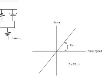
Damper is the most important in suspension system. Damper function is the control of motion or oscillation, as seen with the use of hydraulic gates and valves in a vehicles shock absorber. Like spring rate, the optimal damping for comfort may be less than for control. Damping controls the travel speed and resistance of the vehicles suspension. An undamped car will oscillate up and down. With proper damping levels, the car will settle back to a normal state in a minimal amount of time. Most damping rate in modern vehicles can be controlled by increasing or decreasing the resistance to fluid flow in the shock absorber. Nowadays, there many types of suspension system can make car more comfortable in any road condition. It has five main types of vehicle suspension system like passive, semi-active, slow active, active and fully active suspension system, which depend on the operation mode to improve vehicle ride. A semi-active damper is capable of changing its damping characteristics whether through mechanically changing orifices or fluid with adjustable viscosity; a semi-active damper offers greater variation in damping rate with presence of the control algorithm used in the design which will
governs the amount of damping needed.
8 5
The problem of controlling MR damper rises from this damper constraint. The damper constraint indicates that the output of the disturbance rejection control namely target force that must be tracked by MR damper must be in the same sign with the real time damper velocity. MR damper cannot provide positive force at negative relative velocity of the damper and vice versa. The limitation of semi-active control strategy is that besides having the ability to attenuate the disturbances, it must produce the target force exactly in the same sign with the damper velocity. So, it is important to study the semi active suspension control system namely skyhook, groundhook, and hybrid. This project is useful for optimizing the appropriate tuning parameter to achieve the optimum vibration absorption in both body and wheel response.
8 9 :
Objectives of this project are:
· To study the well known control strategy namely skyhook, groundhook, and hybrid.
· To demonstrate the semi active suspension system in a quarter car model by employing those controller structures.
· To perform or investigate the simulation and experimental work.
8 ;
5
5 8
5 8 8
[image:22.612.163.503.271.531.2]Passive suspension system is a parallel arrangement between passive damper and spring which mean that this system unable to generate force, but only able to dissipate energy at a constant rate due to presence of constant velocity damper. This type of damper had been use for several years in conventional vehicle cause by low cost production.
5 8 5 <
[image:23.612.157.505.432.663.2]Semi-active suspension system is a parallel arrangement between adjustable damper and spring. This type of suspension system unable to generate force, but able to dissipate energy at a variable rate with presence of adjustable damper; there are two type of adjustable damper which is variable orifice and variable fluid viscosity. Variable orifice damper type allows the changing at the size of valve port flow for creating various damping rate of damper fluid with applying current. While, variable fluid viscosity damper type gives a various damping rate by changing the fluid viscosity. The fluid that exhibits the changeability is Magneto Rheological (MR) fluid which will change its viscosity in presence of magnetic coil which can be generate by applying current. And also, this type of damper will be used in this project. This type of suspension system gets more attention in automotive industry due to its safety rather than fully active suspension system because when this system malfunction, it will working as passive suspension system.
5 8 9 <
[image:24.612.213.435.286.435.2]Slow-active suspension system is a parallel arrangement between passive damper, spring and force generation device. This type of suspension system runs as passive suspension system when force generation devise is not working. Presence of force generation devise is able generate external force to remove unwanted motion of vehicle body movement. This type of suspension system need more space for arranging the passive suspension system with force generation devise correspondingly.
Figure 2- 3: Slow Active Suspension System
5 8 ;
Active suspension system is a parallel arrangement between spring and force
generation device. This type of suspension system can exhibit unwanted force when force generation device is malfunction.