PERFORMANCE COMPARISON BETWEEN PID AND FUZZY LOGIC CONTROLLER IN POSITION CONTROL
SYSTEM OF DC SERVOMOTOR
MOHD FUA’AD RAHMAT1 & MARIAM MD GHAZALY2
Abstract. The objective of this paper is to compare the time specification performance between conventional controller and artificial intelligence controller in position control system of a DC motor. This will include design and development of a GUI software using Microsoft Visual Basic 6.0 for position control system experiment. The scope of this research is to apply direct digital control technique in position control system. Two types of controller namely PID and fuzzy logic controller will be used to control the output response. An interactive software will be developed to visualize and analyze the system. This project consists of hardware equipment and software design. The hardware parts involve in interfacing MS150 Modular servo System and Data Acquisition System with a personal computer. The software part includes programming real-time software using Microsoft Visual Basic 6.0. Finally, the software will be integrated with hardware to produce a GUI position control system.
Key words: virtual instrumentation, PID, fuzzy logic, position control system, servomotor, direct digital control, graphic user interface
Abstrak. Objektif kertas kerja ini adalah untuk menyiasat dan membandingkan prestasi spesifikasi masa diantara pengawal konvensional dan pengawal suatu perisian interaktif komputer akan direka dengan menggunakan Microsoft Visual Basic 6.0 yang berupaya mengawal kedudukan shaft motor dalam sistem motor servo. Skop projek ini adalah untuk menggunakan teknik kawalan terus digital dalam mengawal kedudukan shaft motor servo. Pengawal PID dan logik kabur akan digunakan untuk mengawal isyarat keluaran motor servo. Projek ini terbahagi kepada dua bahagian iaitu perkakasan dan perisian. Bahagian perkakasan terdiri daripada membina hubungan antaramuka antara MS150 Modular servo sistem dengan kad perantaramukaan dan komputer peribadi. Bahagian perisian pula adalah lebih kepada mereka bentuk perisian untuk pengawal PID dan logik kabur dengan menggunakan Microsoft Visual Basic 6.0.
Kata kunci: virtual instrumentation, PID, logik kabur, kedudukan sistem kawalan, motor servo, kawalan terus digital
© Universiti Teknologi Malaysia
1
Department of Control and Instrumentation Engineering, Universiti Teknologi Malaysia, 81310 Skudai, Johor. Email: [email protected]
2
1.0 INTRODUCTION
The evolution of programming paradigms was marked by the transition from machine language to assembly languages, and from these to functional, procedural, and, eventually, object- oriented, high-level languages. During these past years, a totally new paradigm evolved along these lines, offering problem solving approaches in a new dimension graphical data flow programming in the form of so called virtual instruments. Virtual instrumentation is defined as a visualization and centralization of complex measurement system on a standard personal computer in the form of a virtual user interface. A user sees a uniform comprehensive single system, consisting of many individual measuring components in a virtual instrumentation(VI).
The main purpose of this research is to design a software based program with Graphical User Interface (GUI) in controlling the position of a servomechanism or also known as servomotor. It involves understanding on how to interface personal computer (PC) with position control system through Data Acquisition System (DAS). This research can be divided into two parts; namely hardware and software. The hardware part involves interfacing MS150 Modular servo System and Data Acquisition System with a personal computer whereas the software part includes programming real-time software using Microsoft Visual Basic 6.0.
2.0 DIRECT DIGITAL CONTROL SYSTEM (DDC)
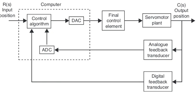
Direct Digital Control (DDC) technology gives today’s industrial user the flexibility to tailor near any system to specific needs using convenient software-based control. A simple concept that has blossomed into a complex array of components and systems, DDC is basically a microprocessor-based technology in which a controller performs closed-loop functions via sophisticated algorithms and strategies. A typical schematic of direct digital control is shown in Figure 1. The controller function handles inputs and outputs electronically while the software provides the logic. Within the controller, the analogue signal enters the system where it is converted to a digital form so that the data can be acted upon according to a set of parameters or formulas. The result is the execution of commands directly to end device. Since the programs used by the controllers are in digital form, the operations are known as direct digital control [2,3].
2.1 PID Controller
PID stands for Proportional-Integral-Derivative. This is a type of feedback controller whose output, a control variable (CV), is generally based on the error between some user-defined set point (SP) and some measured process variable (PV). Each element of the PID controller refers to a particular action taken on the error.
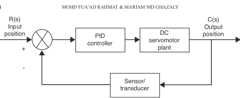
There are many situations that require some type of servo-control system. This section reviews the fundamental of PID controllers and presents detailed simulations or design for development of digital servomotor controller. PID controllers are commonly used to regulate the time-domain behaviour of many different types of dynamic plants. These controllers are extremely popular because they can usually provide good closed loop response characteristics, can be tuned using relatively simple rules and are easy to construct using either analogue or digital components. Consider the feedback system shown in Figure 2 where we assume that the plan is a DC motor whose shaft position must be accurately regulated.
The PID controller K(s) is placed in the forward path, so that its output becomes the voltage applied to the motor’s armature. The feedback signal is either an angular shaft position or velocity, measured by a potentiometer or a tachometer, respectively. In the block diagram, these transducer dynamics are in the feedback path. The output position signal y(t) (or velocity signal) is summed with a reference signal r(t), or command signal, to form the error signal e(t). Finally, the error signal is the input to the PID controller.
Figure 1 Direct digital control schematic
Figure 2 General feedback architecture
2.2 Digital PID Controller
The PID controller is defined by the following relationship between the controller input e(t) and the controller output v(t) that is applied to the motor armature: derivative terms to form suitable for computation by a computer. By using z-transform, we may discretise the analogue PID controller to obtain the pulse transfer function for the digital PID controller as the following equation [4].
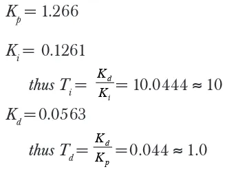
Positional Form of the PID control scheme is given as;
Equation (2) can be written in a sequence operation as in Equation (3). Equation u(k) will be used to develop the coding program for PID controller which corresponds with sequence operation [5].
u(k) = Kpe(k) + KiTs e
e(k) = error between desired value and actual value
e
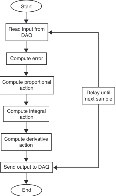
After calculating these values, the coding for the PID controller can be written. The flow chart for the system can be virtualized as in Figure 3.
2.3 Fuzzy Logic Controller (FLC)
2.4 Fuzzification
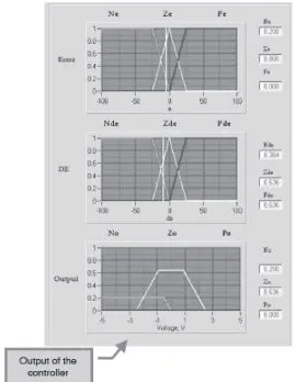
The position control of the servo system configuration was designed based on 2 inputs and 1 output. Inputs for this controller are error and rate (de), and the motor output. Fuzzification is where we define the quantization and membership function for input variable, error and rate (de) and output variable, motor output in universe of discourse. It involves the conversion of the input and output signals into a number of fuzzy represented values (fuzzy sets). Figure 6 shows the input and output variables that are used in the system.
Figure 3 Flow chart for the PID controller system
Start
Read input from DAQ
Compute error
Compute proportional action
Compute integral action
Compute derivative action
Send output to DAQ
End
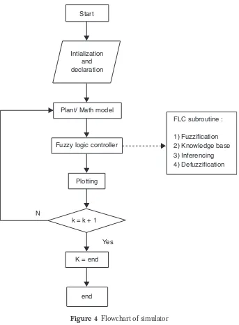
Figure 4 Flowchart of simulator
Plant/ Math model
Fuzzy logic controller
Plotting
k = k + 1
Yes
K = end
end
FLC subroutine :
1) Fuzzification 2) Knowledge base 3) Inferencing 4) Defuzzification Start
Intialization and declaration
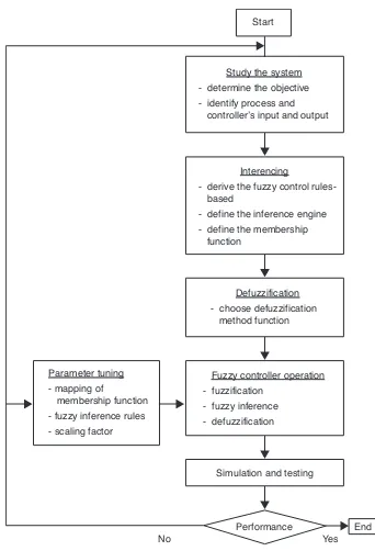
Figure 5 FLC design methodology
Start
Study the system - determine the objective - identify process and controller’s input and output
Defuzzification - choose defuzzification method function Interencing
- derive the fuzzy control based
- define the inference engine - define the membership function
Fuzzy controller operation - fuzzification
- fuzzy inference - defuzzification
Simulation and testing
Performance Parameter tuning
- mapping of
membership function - fuzzy inference rules - scaling factor
Quantization of input and output variables:
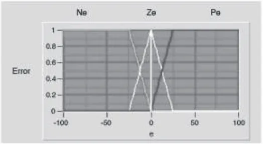
(i). Input variables : • Error(e)
Quantized into 3 fuzzy sets: negative error (Ne), zero error (Ze) and positive error (Pe). Figure 7 shows the error input variable.
Figure 6 The input and output variable
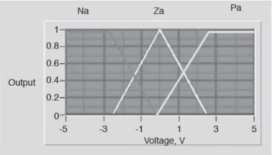
Figure 9 The motor output variable
• Rate(de)
Quantized into 3 fuzzy sets: negative rate (Nde), zero rate (Zde) and positive rate (Pde). Figure 8 shows the rate input variable.
(ii). Output variable:
Figure 8 The rate input variable
• Motor output
2.5 Knowledge Based
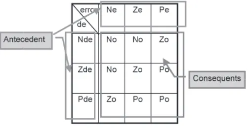
The basic function of the rule based is to represent the expert knowledge in a form of if-then rule structure. The fuzzy logic can than be derived into a 3 × 3 rule which consist of 9 rules. Figure 10 shows the fuzzy logic rules.
The fuzzy logic rules-based are:
1) If error is Ne AND de is Nde THEN output is No 2) If error is Ne AND de is Zde THEN output is No 3) If error is Ne AND de is Pde THEN output is Zo 4) If error is Ze AND de is Nde THEN output is No 5) If error is Ze AND de is Zde THEN output is Zo 6) If error is Ze AND de is Pde THEN output is Po 7) If error is Pe AND de is Nde THEN output is Zo 8) If error is Pe AND de is Zde THEN output is Po 9) If error is Pe AND de is Pde THEN output is Po
2.6 Inferencing
The inference mechanism provides the mechanism for invoking or referring to the rule base such that the appropriate rules are fired. There are several methodologies to derive the Inferencing method. Two most common methods used in fuzzy logic control are the max-min composition and the max-(algebraic) product composition. The inference or firing with this fuzzy relation is performed via the operations between the fuzzified crisp input and the fuzzy relation
representing the meaning of the overall set of rules. As a result of the composition, one obtains the fuzzy set describing the fuzzy value of the overall control output.
For this system, max-min composition is used for the inferencing. Figure 11 shows the firing strength for the rule base using max-min inference.
Figure 11 The firing strength for the rule base using max-min inference
2.7 Defuzzification
z
u z z u z
z
z
& =
$
$
( )
( ) .
(4)
2.8 Hardware Connection
Hardware connection is done by interfacing between Personal Computer and MS150 Modular Servo System through AX5412H Data acquisition card. The connection is shown in Figure 12. There are 8 differential inputs (or 16 single input) and 2 outputs from the AX5412 data acquisition card. Only 2 differential inputs are used for measurement and both outputs are used to control the direction and speed of the motor. The connection between MS150 Modular Servo System and AX5412H data acquisition card will be shown in the experiment procedure respectively.
The driver used in this project is the Axiom Device Manager version 1.1 where AX5412H is set at based address 300 with differential input and output range set at 10v bipolar.
Figure 12 Connection between PC and MS150 through AX750 Screw Terminal Panel AX750 Screw Terminal Panel MS 150 Modular Servo System
3.0 PID RESULTS
The waveform obtained from the direct digital control experiment is then analyzed. The terms defined above are used for each combination of PID controller. Figure 13 shows the result which is captured within the GUI. Table 1 shows the analysis of the best output result which is captured within the GUI. All the system characteristics terms are analyzed using Yokogawa DL1546 Digital Oscilloscope. The unit used for rise time, Tr, settling time, Ts, peak time, Tp are all is milliseconds (ms). %OS is in percentage (%), ' is dimensionless, (n is rad/ s and unit for steady state error, ess is in Volt.
3.1 Fuzzy Logic Results
The waveform obtained through the direct digital control experiment was analyzed. The terms defined above were used for the fuzzy logic controller. Figure 14 shows the result which is captured within the GUI. From the capture result, it can be concluded that the output response of the fuzzy logic controller has a percentage overshoot of 0.8V that is 16% overshoot.
4.0 DISCUSSION
The output response of both the PID and Fuzzy logic were compared. Table 2 shows the comparison between the output response using the PID and Fuzzy logic. From the analysis and comparison of both controllers, the PID controller
Table 1 The analysis of PID controller output result
Gain (%)
System
characteristic Output waveform
P=10
I=100
D=50
%OS = 0 Tr=415.38
Ts = 538.46 Tp=476.92
'= 0.66
(n= 11.27 ess= 0.10
performs better compared to Fuzzy logic in terms of percentage overshoot, with 0% overshoot compared to fuzzy logic with an overshoot of 16%. But, when comparing both of the rise time and settling time of both controllers, the fuzzy logic controller performs better, with a Tr of 400.00 ms and Tsof 100 ms.
5.0 CONCLUSION
PID controllers are commonly used to regulate the time-domain behavior of many different types of dynamic plants. These controllers are extremely popular because they can usually provide good closed loop response characteristics, can be tuned using relatively simple rules and are easy to construct using either analogue or digital components. To discretise the PID controller, we need to approximate the integral and the derivative terms to forms suitable for computation by a computer. By using z-transform, we may discretise the analogue PID controller to obtain the pulse transfer function for the digital PID controller. Then, equation u (k) is used to develop the coding program for the PID controller which corresponds with the sequence operation.
mapping from a space of fuzzy control actions defined over an output universe of discourse into a space of non-fuzzy (crisp) control action. For this system, centroid method is used for defuzzification.
REFERENCES
[1] Axiom AX5412-H Data Acquisition Board User Manual
[2] Auslander, D.M. 1990. Real-time Software for Control. Prentice Hall.
[3] Perdikaris, G.A. 1991. Computer Controlled Systems-Theory and Application. Kluwer Academic Publisher. [4] Ogata, K. 1995. Discrete Time Control Systems. 2nd edition. Prentice Hall.