www.ijera.com 136|P a g e
Regression Analysis and Analysis Of Variance for EN353
and20MnCr5 Alloyed Steels for Drilling Cutting Forces
Keerthiprasad.K
1, Prof Narendra Babu
2, Dr Chandrashekara
3ABSTRACT
In recent years, alloy steels have been widely usedin aerospace and automotive industries. Machining of these materials requires better understanding of cutting processes regarding accuracy and efficiency. This study addresses the modelling of the machinability of EN353 and 20mncr5 materials. In this study, multiple regression analysis (MRA) is used to investigate the influence of some parameters on the thrust force and torque in the drilling processes of alloy steel materials. The model were identified by using cutting speed, feed rate, and depth as input data and the thrust force and torque as the output data. The statistical analysis accompanied with results showed that cutting feed (f) were the most significant parameters on the drilling process, while spindle speed seemed insignificant. Since the spindle speed was insignificant, it directed us to set it either at the highest spindle speed to obtain high material removal rate or at the lowest spindle speed to prolong the tool life depending on the need for the application. The mathematical model is based on a power regression modelling, dependent on the three above mentioned parameters.
I.
INTRODUCTION
There are, almost, 100 years since alloyed steels have been “discovered” and, nowadays, their application fields are various and challenging. That is because of their important physical and mechanical characteristics. These steels are very tough, with low thermal conductivity and, while machining, determines severe wear of the cutting tool, as well as, high value cutting forces. Because of their high prices, researches on their machinability are necessary, in order to optimize the machining process, having high productivity and low costs of steel parts. One important aspect of material’s machinability is represented by the values of the cutting force and torque, meaning the higher the values, the lower machinability is so, resulting low energy efficiency use. Specific literature presents some relationships regarding variables of the machining process – involving force and torque but, when experimentally checking them, one can notice, relative high difference (of the modelled ones) from the real obtained values .
So, it has been considered useful to determine adequate models of some machining process parameters, regarding one widely used alloyed steels EN353and 20MnCr5. Obtaining holes, in steel parts, of various dimensions and precisions, is done by drilling. Cutting force, especially axial one, and cutting torque, are important parameters (output variables) of the drilling process and, can be often used for its optimization. Based on the above, this paper presents the experimental steps carried out in order to determine some mathematical models of axial cutting and torque in drilling EN353 and 20MnCr5 steels.
Based on experimental researches were obtained mathematical models of drilling. These models involve three factors: cutting depth [mm], speed[r/min] and feed [mm/rev]. If a mathematical model is dependent on so many coefficients and constants, it is difficult to assess whether it matches with the whole range of materials and tools. In this context, was intended to determine a mathematical model for a particular material, with a particular tool. Because the EN353 and 20MnCr5 alloyed steels is widely used in industry
1.1 STEELS
The term steel is used for many different alloys of iron. These alloys vary both in the way they are made and in the proportions of the materials added to the iron. All steels, however, contain small amounts of carbon and manganese. In other words, it can be said that steel is a crystalline alloy of iron, carbon and several other elements, which hardens above its critical temperature.
1.2 CLASSIFICATIONS OF STEELS
Steels can be classified by a variety of different systems depending on:
The composition, such as the chemical composition percentage of carbon.
The manufacturing methods, such as open hearth, basic oxygen process, or electric furnace methods.
The finishing method, such as hot rolling or cold rolling
The product form, such as bar, plate, sheet, strip, tubing or structural shape
The microstructure, such as ferrite, pearlite and martensitic
The required strength level, such as high or low tensile strength steel
The heat treatment, such as annealing, quenching and tempering steel.
1.2.1 Carbon Steels
Carbon steel is an iron-based metal containing carbon up to 2%, and small amounts of other elements (Mn, Si, S, and P). Variations in carbon have the greatest effect on mechanical properties, with increasing carbon content leading to increased hardness and strength. As such, carbon steels are generally categorized according to their carbon content. Generally speaking, carbon steels can be subdivided into low-carbon steels, medium-carbon steels and high-carbon steels
1.2.2 Low Carbon Steels
Of all the different steels, those produced in the greatest quantities fall within the low-carbon classification. These generally contain less than about 0.25 wt% C and are unresponsive to heat treatments intended to form martensite; strengthening is accomplished by cold work. Microstructures consist of ferrite and pearlite constituents. As a consequence, these alloys are relatively soft and weak, but have outstanding ductility; in addition, they are machinable, weldable, and, of all steels, are the least expensive to produce. Typical applications include automobile body components, structural shapes (I-beams, channel and angle iron), and sheets that are
The medium-carbon steels have carbon concentrations between about 0.25 And 0.60 wt%. These alloys may be heat treated by quenching, and then tempering to improve their mechanical properties. They are most often utilized in the tempered condition, having microstructures of tempered martensite. The plain medium-carbon steels have low hardenability’s and can be successfully heat treated only in very thin sections and with very rapid quenching rates. Applications include railway wheels and, gears, crankshafts, and other machine parts.
1.2.4 High-Carbon Steels
The high-carbon steels, normally having carbon contents between
0.60 And 1.4 wt%, are the hardest, strongest, and yet least ductile of the carbon steels. They are almost always used in a hardened and tempered condition and, as such, are especially wear resistant and capable of holding a sharp cutting edge. Application includes blacksmith tools and wood working tools.
1.2.5 Alloy Steels
Alloy steels are made by combining steels with one or more other elements. These elements are usually metals .they are intentionally added to obtain properties that are not found in plain carbon steels .An alloy is a mixture of two or more metals, or a metal and some other material. Most alloy contain a large amount of one metal, called the base metal, and smaller amounts of one or more other metals or non-metallic materials. Many pure metals are too soft, corrode too easily, or have other mechanical or chemical disadvantages can be overcome if the metals are combined with other metals into alloys. Most alloys are harder than the metals from which they are made. They are also less malleable. They are harder to hammer into shape. Most alloys are less ductile than pure metals. That is, they are less easily drawn into fine wires and similar shapes. But most alloy are more fusible and more easily melted, than the pure metals of which they are composed. Some alloys will even melt at the comparatively low temperature of hot water. Few alloys can conduct electricity as well as many metals in their pure forms.
1.3 EFFECTS OF ALLOYING ELEMENTS IN STEEL
Alloying elements are added to effect changes in the properties of steels. The basis of this section is to cover some of the different alloying elements added to the basic system of iron and carbon, and what they do to change the properties or effectiveness of steel.
1.3.1 Carbon
As I've already stated, the presence of carbon in iron is necessary to make steel. Carbon is essential to the formation of cementite (as well as other carbides), and to the formation of pearlite, spheroidite, bainite, and iron-carbon martensite, with martensite being the hardest of the micro-structures, and the structure sought after by knife makers. The hardness of steel (or more accurately, the hardenability) is increased by the addition of more carbon, up to about 0.65 percent. Wear resistance can be increased in amounts up to about 1.5 percent. Beyond this amount, increases of carbon reduce toughness and increase brittleness. The steels of interest to knife makers generally contain between 0.5 and 1.5 percent carbon. They are described as follows:
• Low Carbon: Under 0.4 percent • Medium Carbon: 0.4 - 0.6 percent • High Carbon: 0.7 - 1.5 percent
Carbon is the single most important alloying element in steel.
1.3.2 Manganese
www.ijera.com 138|P a g e quenching speed. This also makes the steel more
stable in the quench. Steels with manganese can be quenched in oil rather than water, and therefore are less susceptible to cracking because of a reduction in the shock of quenching. Manganese is present in most commercially made steels.
1.3.3 Chromium
As with manganese, chromium has a tendency to increase hardness penetration. This element has many interesting effects on steel. When 5 percent chromium or more is used in conjunction with manganese, the critical quenching speed is reduced to the point that the steel becomes air hardening. Chromium can also increase the toughness of steel, as well as the wear resistance. Probably one of the most well-known effects of chromium on steel is the tendency to resist staining and corrosion. Steels with 14 percent or more chromium are referred to as stainless steels. A more accurate term would be stain resistant. Stainless tool steels will in fact darken and rust, just not as readily as the non-stainless varieties. Steels with chromium also have higher critical temperatures in heat treatment.
1.3.4 Silicon
Silicon is used as a deoxidizer in the manufacture of steel. It slightly increases the strength of ferrite, and when used in conjunction with other alloys can help increase the toughness and hardness penetration of steel.
1.3.5 Nickel
Nickel increases the strength of ferrite, therefore increasing the strength of the steel. It is used in low alloy steels to increase toughness and hardenability. Nickel also tends to help reduce distortion and cracking during the quenching phase of heat treatment.
1.3.6 Molybdenum
Molybdenum increases the hardness penetration of steel, slows the critical quenching speed, and increases high temperature tensile strength.
1.3.7 Vanadium
Vanadium helps control grain growth during heat treatment. By inhibiting grain growth it helps increase the toughness and strength of the steel.
1.3.8 Tungsten
Used in small amounts, tungsten combines with the free carbides in steel during heat treatment, to produce high wear resistance with little or no loss of toughness. High amounts combined with chromium gives steel a property known as red hardness. This means that the steel will not lose its working hardness at high temperatures. An example of this would be
tools designed to cut hard materials at high speeds, where the friction between the tool and the material would generate high temperatures.
1.3.9 Copper
The addition of copper in amounts of 0.2 to 0.5 percent primarily improves steels resistance to atmospheric corrosion. It should be noted that with respect to knife steels, copper has a detrimental effect to surface quality and to hot-working behaviour due to migration into the grain boundaries of the steel.
1.3.10 Niobium
In low carbon alloy steels Niobium lowers the transition temperature and aids in a fine grain structure. Niobium retards tempering and can decrease the hardenability of steel because it forms very stable carbides. This can mean a reduction in the amount of carbon dissolved into the austenite during heat treating.
1.3.11boron
Boron can significantly increase the hardenability of steel without loss of ductility. Its effectiveness is most noticeable at lower carbon levels. The addition of boron is usually in very small amounts ranging from 0.0005 to 0.003 percent.
1.3.12 Titanium
This element, when used in conjunction with Boron, increases the effectiveness of the Boron in the hardenability of steel.
1.4 ADVANTAGES OF ALLOYED STEELS General effects of alloying elements are: (i) Improved tensile strength without appreciably lowering ductility.
(ii) Improved toughness.
(iii) Improved hardenability which permits hardening of larger sections than possible with plain carbon steels or allows quenching with less drastic rates. (iv) Reducing the hazard of distortion and quench cracking.
(v) Retain strength at elevated temperatures. (vi) Obtain better corrosion resistance. (vii) Improved wear resistance.
(viii) Imparts a fine grain structure to the steel. (ix) Improved special properties such as abrasion resistance and fatigue behaviour.
1.5 LINEAR REGRESSION ANALYSIS
enough in on-line help and spread sheet documentation (i.e. items in the regression input dialog box). However, the description of the output is minimal and is often a mystery for the user who is unfamiliar with certain statistical concepts.
1.6 CLASSIFICATION OF REGRESSION MODELS
In a regression analysis we study the relationship, called the regression function, between one variable y, called the dependent variable, and several others xi, called the independent variables. Regression function also involves a set of unknown parameters bi. If a regression function is linear in the parameters (but not necessarily in the independent variables!) we term it a linear regression model. Otherwise, the model is called non-linear. Linear regression models with more than one independent variable are referred to as multiple linear models, as opposed to simple linear models with one independent variable.
1.7 ANALYSIS OF VARIANCE (ANOVA) Different factors affect the response(s) to a different degree. The relative magnitude of the factor effects could be judged from their factor levels, which gives the average efficiency for each factor level. A better feel for the relative effect of the different factors can be obtained by the decomposition of variance, which is commonly called Analysis Of Variance (ANOVA). ANOVA is also needed for estimating the error variance for the factor effects and variance of the prediction error. These aspects are used in the present study.
1.7.1. Interpretation of ANOVA Tables
Larger the contribution of a particular factor to the total sum of squares, the larger the ability is of that factor to influence η. The largeness of a factor effect relative to the error variance can be judged from the F column. The larger the F value, the larger the factor effect is compared to the error variance.
1.8 OBJECTIVE OF THE STUDY
In recent years, alloy steels have been widely used in aerospace and automotive industries. Machining of these materials requires better understanding of cutting processes regarding accuracy and efficiency. The purpose of this project is to establish thrust and torque models of drilling processes for cutting conditions. Such models are potentially useful in a global drilling process simulation for prediction of tool motion and the generation of surface topography for a concurrent engineering design system, this work is surely needed for meeting tolerance requirements, process planning, and system monitoring.
II.
LITERATURE REVIEW
2. IMPORTANT ASPECTS IN DRILLING 2.1 Cutting force Large torque, which often indicates more friction between the drills and work piece, can produce a large quantity of heat, causing higher temperature at the tool-work piece interface. It was reported that the cutting force when drilling alloyed steels was higher than that when drilling aluminium alloys, similar to that when drilling steels. The power consumption when drilling alloyed steels was approximately the same as or lowers than that when drilling low hardness steels. The cutting force and power consumption when drilling different metals. Although the cutting force when machining Alloyed steels is not much higher than that when machining other metals, much higher stresses occur in the immediate vicinity of the cutting edge when machining alloyed steels. Konig (1979) reported higher stresses on the tool when machining alloyed steels-6Al-4V than those when machining a nickel-based alloy, and three to four times higher than those when machining steel. He attributed this to the unusually small chip-tool contact area on the rake face (about one-third of that when machining steel for the same feed rate and depth of cut), and partly to the resistance of Alloyed steels to deformation at elevated temperatures.
2.2 Cutting temperature
www.ijera.com 140|P a g e 2.3 Tool wear and tool life
Alloyed steel chips can easily weld to the cutting edges of the tool ( built-up-edge, or, BUE). It is adhesion between the tool and workpiece (Narutaki and Murakoshi, 1983). And the high stresses developed at the cutting edge of the tool may cause plastic deformation and/or accelerate the tool wear (Dearnley and Grearson, 1986; Dornfeld, 1999; Ezugwu, 1997; Konig, 1979; Sharif and Rahim, 2007; Yang and Liu, 1999).
Wear mechanisms in machining alloyed steels may vary according to different tool/workpiece material combinations. Notching, non-uniform flank wear, crater wear, chipping, and catastrophic failure are the prominent failure modes when drilling alloyed steels (Ezugwu, 1997; Rahim and Sharif, 2006; Sharif and Rahim, 2007). Severe tool wear is the main reason for the high cost of alloyed steels drilling. The cutting speed must be sufficiently low to avoid too short tool life. In order to ensure the tool life, it usually takes a longer time to drill Ti than steel (Yang and Liu, 1999).Shows relative time consumption when drilling different metals.
2.4 Drill quality
Hole quality in drilling Alloyed steels is evaluated in terms of hole diameter, cylindricity, surface roughness, and burr. Alloyed steels is generally used for parts requiring the great reliability and resistance of wear, and therefore high hole quality must be maintained. Higher surface roughness can possibly lead to severe wear, catastrophic fatigue, and lower ability to resist corrosion. However, the surface of alloyed steels is easily damaged during machining operations (Child and Dalton, 1965; Konig and Schroder, 1975). Damage appears in the form of micro cracks, plastic deformation, heat-affected zones, and tensile residual stresses. Two critical criteria (hole diameter and cylindricity) were usually applied to determine the hole quality in terms of size and shape. The average hole diameter has to be within the size tolerance which is described as two concentric circles. Cylindricity is the extension of roundness into the entire length of the hole. The cylindricity tolerance zone is established by two concentric cylinders between which the machined hole (a cylinder) must lie (Anonymous, 2007; Kim. 2001). Most Alloyed steels drilling processes will create a burr on both entrance and exit surfaces. In most cases the main concern is the exit burr which is much larger in size. Burr formation in alloyed steels drilling is troublesome in aerospace applications. It is estimated that up to 30% of the cost of some
components is due to deburring operations (Dornfeld, 1999).
2.5 Chip type
In twist drilling and vibration assisted twist drilling, the alloyed steels chip could be entangled around two flutes of the drill and bent by the tool holder. This chip entanglement will cause difficulty for smooth chip ejection (Li, 2007). The characteristic of the chip formation in twist drilling of alloyed steels is different from other metals (Kim and Ramulu, 2005; Yang and Liu, 1999). Yang and Liu (1999) categorized the alloyed steels chips into three types: continuous chip, continuous chip with built-up edge, and discontinuous chip. The distinctive features of alloyed steels chip can be described as serrated, shear-localized, discontinuous, cyclic, and segmented. There are two main shapes of chip morphology: spiral cone chip and folded long ribbon chip. It has reported that the spiral cone chip is easier to be ejected so the length of spiral cone chip can be considered as a scale to evaluate the difficulty for chip evacuation in drilling. Generally, Alloyed steels chips are thin and the flow zone between the chip and the tool is also much thinner (approximately 8 µm compared with 50 µm when cutting iron under the same cutting conditions) than some other metals, so the tool-tip temperatures can be up to about 1100ºC (Motonishi, 1987; Narutaki and Murakoshi, 1983). Besides, the adhesion often occurs easily to the tip of the drill when drilling alloyed steels and it will lead to the increase in the cutting resistance and chip jamming within the flutes of drill (Okamura 2006). As a result, it leads to the drill breakage and the decrease of the hole accuracy.
2.6 Effects of feed rate
The most significant parameter of a drilling process affecting the cutting force is feedrate. It has been consistently reported that an increase in feedrate would increase the thrust force (Kim and Ramulu, 2005; Kim, 2005; Lambert, 1979; Ramulu, 2001; Rao, 1990) and the torque (Kim, 2005; Lambert, 1979; Rao, 1990).
2.7 Effects of cutting speed
It was reported that an increase in cutting speed
2.8 Effects of drill geometry and material
When the side cutting edge angle increased, the cutting force and torque would increase (Zhu and Wang, 2006). A larger helix angle would reduce both thrust force and torque (Rao, 1990). Rake angle was found to have little impact on the cutting force (Zhu and Wang, 2006). The exact effects of other geometric parameters are not available in the literature. Li (2007) reported that WC-Co drills performed better than HSS tools because of lower thrust force and torque. The WC-Co spiral drills (a kind of twist drill with advanced geometric design with S-shaped chisel edge and lower negative rake angle than that of the conventional twist drill) produced lower cutting force and torque than WC-Co twist drill, Kim(2001) reported that, when drilling Steels graphite stacks, the torque with HSS-Co tools was at least 40% higher than that with carbide tools.
2.9 Effects of coolant
Li (2007) reported that the external coolant supply had no obvious effect on the thrust force and torque, but internal coolant supply could slightly increase the thrust force (likely caused by the hydrodynamic force) and the consumed energy during the drilling process.
2.10 Effects of other factors
Kim and Ramulu (2005) reported that typical thrust force and torque profiles varied with cutting depth as the drill penetrated the composite material when drilling Steels/composite stacks. Thrust force increased proportionally to an optimal depth then it dropped to a lower level for higher depth of cut. The thrust force was the maximum as the drill penetrated Steels and the maximum torque occurred when the drill lips cut both composite and Steels simultaneously. Lambert (1979) reported that the drilling force could be influenced significantly by the drilling time. Increased drilling time resulted in increased thrust force.
TECHNICAL PAPERS REFERRED
S. C. Lin, I. K. Chen [1] studied the effects of increasing cutting speed on drilling characteristics of alloyed steels. The effects of increasing cutting speed ranging from 9550 up to 38650 rev min”1 (from 210 to 850 m min”1) on average thrust force, torque, tool
wear and hole quality for both multifacet drill and twist drill are studied. It was found that increasing cutting speed will accelerate tool wear. And the thrust force increases as drill wear increases. Although tool geometries change quickly due to the fast development of tool wear and the thrust force increases drastically as cutting speed increases, an acceptable hole entry and exit quality is maintained. This is because relatively small feeds are used in these tests. It was concluded that tool wear was the major problem encountered when drilling steels at high speed.
R. Stone and K. Krishnamurthy [2] studied the linear-elastic fracture mechanics theory which proposed critical cutting and thrust forces in the various drilling regions that can be used as a guide in preventing crack growth . Using these critical force curves as a guide, a thrust force controller was developed to minimize the delamination while drilling steels. A neural network control scheme was implemented which re network identifier to model the drilling dynamics and a neural network controller to learn the relationship between feed rate and the desired thrust force. Experimental results verifying the validity of this control approach as well as the robustness of the design are presented. Visual measurements of the delamination zones were used to quantify the benefits of the thrust force controlled drilling process versus the conventional constant feed rate drilling process.
J. Mathew, N.Ramakrishnan and N. K. Naik [3] studied that thrust is a major factor responsible for surface crack and it mainly depends on tool geometry and feed rate. Trepanning tools, which were used in this study, were found to give reduced thrust while making holes on thin sheet metals.
III.
TESTING AND RESULTS
The testing for the chosen materials(EN353 and 20MnCr5) are carried out using drill tool dynamometer for different spindle speed, feed rate and drill diameter to find thrust, torque and power .the results are tabulated below.
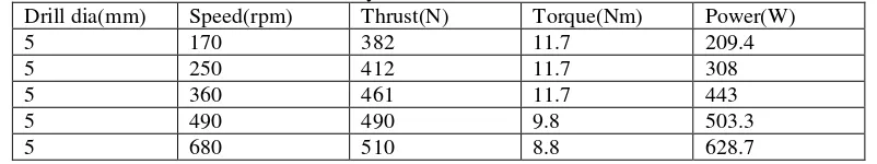
Table: 3, Values obtained by EN353 material for feed rate 0.095mm/rev Drill dia(mm) Speed(rpm) Thrust(N) Torque(Nm) Power(W)
5 170 382 11.7 209.4
5 250 412 11.7 308
5 360 461 11.7 443
5 490 490 9.8 503.3
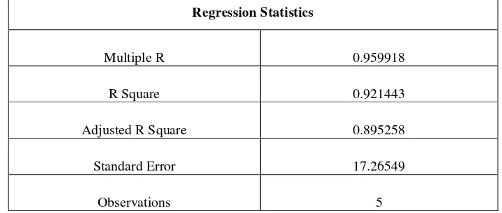
www.ijera.com 142|P a g e Table: 3.1 MRA Test Results for en353 material using 5mm HSS drill tool for feed rate 0.095mm/rev
Regression Statistics
Multiple R 0.959918
R Square 0.921443
Adjusted R Square 0.895258
Standard Error 17.26549
Observations 5
Table 3.2 ANOVA Test Results for en353 material using 5mm HSS drill tool for feed rate 0.095mm/rev
ANOVA
df SS MS F Significance F
Regression 1 10489.71 10489.71 35.18889 0.009575
Residual 3 894.2914 298.0971 Total 4 11384
Table 3.3 Variable Test Results for en353 material using 5mm HSS drill tool for feed rate 0.095mm/rev
Coefficients Standard
Error t Stat P-value
Lower 95%
Upper 95%
Lower 95.0%
Upper 95.0%
Intercept 352.0644 18.37886 19.15595 0.0003111 293.5747 410.5541 293.5747 410.5541
X Variable 1 0.253681 0.042765 5.932023 0.009575 0.117585 0.38977 0.117585 0.38977
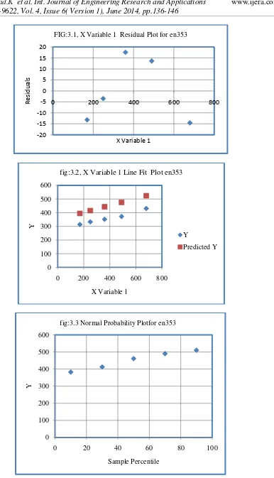
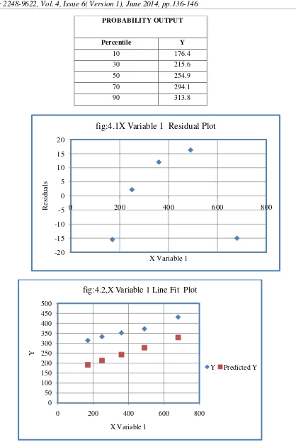
Table 3.4 Residual Output and Probability output Results for en353 material using 5mm HSS drill tool for feed rate 0.095mm/rev
RESIDUAL OUTPUT
PROBABILITY OUTPUT
Observation Predicted
Y Residuals
Standard
Residuals Percentile Y
1 395.1902 -13.1902 -0.88215 10 382
2 415.4847 -3.48466 -0.23305
30 412
3 443.3896 17.61043 1.17777
50 461
4 476.3681 13.6319 0.911689
70 490
5 524.5675 -14.5675 -0.97426
-20 -15 -10 -5 0 5 10 15 20
0 200 400 600 800
Re
s
id
u
al
s
X Variable 1
FIG:3.1, X Variable 1 Residual Plot for en353
0 100 200 300 400 500 600
0 200 400 600 800
Y
X Variable 1
fig:3.2, X Variable 1 Line Fit Plot en353
Y
Predicted Y
0 100 200 300 400 500 600
0 20 40 60 80 100
Y
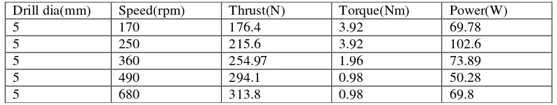
www.ijera.com 144|P a g e TABLE: 4 Values obtained by 20MnCr5 material for feed rate 0.095mm/rev
Table 4.1 MRA Test Results for 20mncr5 material using 5mm HSS drill tool for feed rate 0.095mm/rev REGRESSION STATISTICS
Multiple R 0.964551
R Square 0.930359
Adjusted R Square 0.907146
Standard Error 17.12608
Observations 5
Table 4.2 ANOVA Test Results for 20mncr5 material using 5mm HSS drill tool for feed rate 0.095mm/rev ANOVA
df SS MS F Significance F
Regression 1 11755.06 11755.06 40.0783 0.007969
Residual 3 879.9074 293.3025
Total 4 12634.97
Table 4.3 Variable Test Results for 20mncr5 material using 5mm HSS drill tool for feed rate 0.095mm/rev Coefficient
s
Standard Error
t Stat P-value Lower 95%
Upper 95%
Lower 95.0%
Upper 95.0% Intercep
t
146.227 18.2304 8.0210 0.0040 88.209 204.244 88.209 204.244
X Variable
1
0.26854 0.04241 6.33074 0.0079 0.1335 0.4035 0.1335 0.40354
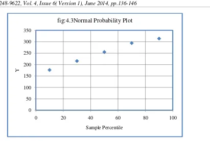
Table 4.4 Residual Output and Probability output Test Results for 20mncr5 material using 5mm HSS drill tool for feed rate 0.095mm/rev
RESIDUAL OUTPUT
Observation Predicted Y Residuals Standard Residuals
1 191.8799 -15.4799 -1.04371
2 213.3636 2.236442 0.150789
3 242.9036 11.99638 0.808838
4 277.8146 16.2854 1.098019
5 328.8383 -15.0383 -1.01394
Drill dia(mm) Speed(rpm) Thrust(N) Torque(Nm) Power(W)
5 170 176.4 3.92 69.78
5 250 215.6 3.92 102.6
5 360 254.97 1.96 73.89
5 490 294.1 0.98 50.28
0 50 100 150 200 250 300 350 400 450 500
0 200 400 600 800
Y
X Variable 1
fig:4.2,X Variable 1 Line Fit Plot
Y Predicted Y PROBABILITY OUTPUT
Percentile Y
10 176.4
30 215.6
50 254.9
70 294.1
90 313.8
-20 -15 -10 -5 0 5 10 15 20
0 200 400 600 800
R
es
idual
s
X Variable 1
www.ijera.com 146|P a g e
IV.
CONCLUSION
This paper presented the methodology applied to obtain a mathematical model for drilling thrust force. The mathematical model resulted is dedicated to EN353 and 20MnCr5 steel and its processing with HSS drills. It is dependent on three drilling parameters: cutting depth [mm], cutting speed (rpm) and feed rate (mm/rev), which is represented, in the mathematical model. Hence, these models can be used efficiently for prediction potentials for non-experimental patterns which, in turn, save experimental time and cost.
The following general conclusions are made:
Both mathematical models, for axial drilling force and drilling torque, are, somewhat, correlated, meaning it resulted the same, similar, influences of the independent variables studied.
Cutting speed and tool diameter are the predominant factor which governs the dependent variables.
The correlation coefficients guaranteed that the mathematical model accurately reflected the obtained data from the research experiment.
REFERENCES
[1] Badan, I., Oancea, Gh.:Software Tool Used for
Holes Modelling in AutoCAD 3rd
Environment. In: The WSEAS International Conference Engineering Mechanics Structures, Engineering. Geology, Corfu Island, Greece, July 22-2, 2010, p. 152-156.
[2] Chandramohan, D., et al.: Thrust Force and Torque in Drilling the Natural Fibre Reinforced Polymer Composite Materials and
Evaluation of Delamination Bulletin of the Transylvania University of Brasov • Series I • Vol.5 (54) No. 1 -2012 Factor for Bone Graft Substitutes -A Work of Fiction Approach. In: International Journal of Engineering Science and Technology 2 (2010) No. 10, p. 6437-6451.
[3] Chicos, L.A.: Utilizareaconceptului de ingineriesimultata in dezvoltarea de produse (Using the Simultaneous Engineering Concept in Product Development). In: PhD. Thesis, Transilvania University of Brasov, Romania, 2007.
[4] Erkki, J.:
International Journal of Machine Tools & Manufacture 42 (2002), p. 997-1010.
[5] Ertunc, H.M., Oysu, C.: Drill Wear Monitoring Using Cutting Force Signals. In: Mechatronics 14 (2004), p. 533-548.
[6] Gopal Krishna, P.V., et al.: Some Investigations in Friction Drilling AA6351 Using High Speed Steel Tolls. In: ARPN Journal of Engineering and Applied Sciences 5 (2010) No. 3, p. 11-15.
0 50 100 150 200 250 300 350
0 20 40 60 80 100
Y