A MULTI-SENSOR MICRO UAV BASED AUTOMATIC RAPID MAPPING SYSTEM
FOR DAMAGE ASSESSMENT IN DISASTER AREAS
E. Jeon, K. Choi, I. Lee*, H. Kim
Dept. of Geoinformatics, The University of Seoul, 163 Seoulsiripdaero, Dongdaemun-gu, Seoul 130-743, Korea – (dmldlr0323, shale, iplee, zzimss)@uos.ac.kr
Commission I, ICWG I/Vb
KEY WORDS: Mapping, Aerial, On-line, Automatic, Orthoimage, UAV, Sensor, Damage, Disaster
ABSTRACT:
Damage assessment is an important step toward the restoration of the severely affected areas due to natural disasters or accidents. For more accurate and rapid assessment, one should utilize geospatial data such as ortho-images acquired from the damaged areas. Change detection based on the geospatial data before and after the damage can make possible fast and automatic assessment with a reasonable accuracy. Accordingly, there have been significant demands on a rapid mapping system, which can provide the orthoimages of the damaged areas to the specialists and decision makers in disaster management agencies. In this study, we are developing a UAV based rapid mapping system that can acquire multi-sensory data in the air and generate ortho-images from the data on the ground in a rapid and automatic way. The proposed system consists of two main segments, aerial and ground segments. The aerial segment is to acquire sensory data through autonomous flight over the specified target area. It consists of a micro UAV platform, a mirror-less camera, a GPS, a MEMS IMU, and sensor integration and synchronization module. The ground segment is to receive and process the multi-sensory data to produce orthoimages in rapid and automatic ways. It consists of a computer with appropriate software for flight planning, data reception, georeferencing, and orthoimage generation. In the middle of this on-going project, we will introduce the overview of the project, describe the main components of each segment and provide intermediate results from preliminary test flights.
1. INTRODUCTION
As the frequencies and scales of natural disasters tend to increase, there have been significant needs for more accurate and rapid assessment of the damaged areas for their appropriate restoration. For example, damage assessment is recommended to be completed within seven days after the disaster by law in Korea. But it is hardly achieved due to the lack of sufficient budget, experienced personnel, and efficient systems.
Damage assessment has been performed mainly using sensory data acquired by photogrammetric and remote sensing systems, such as satellite or aerial images (Lazarudou, 2011). As a platform carrying such remote sensors as cameras and laser scanners, a satellite or manned aircraft has been mainly used (Tralli, 2005; Huggel, 2002). But these platforms have limitations such as high expenditure, poor mobility and temporal resolution. These limitations can be overcome by the use of a micro UAV as the platform (Eisenbeiss, 2004).
Recent studies show that UAVs are cost-and-time effective systems for acquiring geospatial information (Thar, 2012). However, the accuracy of the results obtained from the systems is not satisfactory and the processing time for the generation of the geospatial information is too long for certain applications. Moreover, UAVs are not so easy to manipulate in general, which requires a long-term training courses for its operation. Even a skilled operator often experiences an unexpected crash (d’Oleire-Oltmanns, 2012). After successfully acquiring the sensory data such as images and GPS/INS data, a user may need a considerable effort and time to generate orthoimages or digital elevation model from the data. In addition, one may need deep knowledge on photogrammetric principles and processes.
However, most peoples in application fields are not familiar with or not interested in UAV operation and photogrammetric processes but only need to acquire the final results, for examples, the orthoimages of the damaged areas, which can be properly overlapped with the existing geospatial information for change detection. This brings the most important motivation of this study, the development of an automatic rapid mapping system based on UAV. Once a user just defines a region of interest on a digital map or orthoimage such as Google Earth with a desired ground resolution, the system can automatically collect sensory data and process them to generate the orthoimages of the target areas within 2 hours with the specified resolution without any user intervention.
While performing a project to develop such a UAV-based automatic rapid aerial mapping system with appropriate software, we present intermediate results in this paper by describing the brief overview of the prototype system, the main components of the aerial hardware and the ground processing software. This aerial system is a micro UAV equipped with the sensors including a digital camera, a GPS and a MEMS IMU. The ground system includes automatic flight planning and geospatial information generation software.
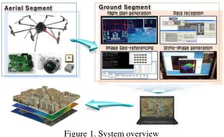
2. SYSTEM OVERVIEW
This system consists of two parts, aerial and ground segments. The aerial segment acquires sensory data through autonomous flight over a specified target area. It is composed of a micro UAV platform, a digital camera, a GPS, a MEMS IMU, and a control-board that records the sensory data tagged with their acquisition times and transmits them to the ground segment after the flight. The ground segment is composed of a flight
planning, data reception, georeferencing, and orthoimage generation software. The overview of the system is presented in Figure 1.
Figure 1. System overview
Once a user selects the area of interest, first of all, the ground segment conducts flight planning and transmits them to the UAV. Secondly, the UAV flies automatically according to the transmitted flight plan. During the flight, the sensors mounted to the UAV acquire imagery and navigational data. After the UAV lands on the ground, the data reception software detects the acquired data and wirelessly receives them from the control board. Finally, the orthoimage generation software generates orthoimages from the received data.
3. INTERMEDIATE RESULTS
Until now, we have constructed the aerial segment and developed some ground software. We introduce the main components of the aerial segment and the main functions of the ground segment.
3.1 Aerial Segment
The aerial segment is to acquire sensory data in the air and wirelessly convey them to the ground segment after the flight. The aerial segment consists of a micro UAV, sensors, and a control board. The sensors include a digital camera, a GPS and a MEMS IMU, as shown in Figure 2.
Figure 2. Aerial segment
3.1.1 UAV Platform: We constructed a customized Micro UAV platform, an octocopter with eight rotors, by assembling the components of the OktoKopter XL from Mikrokopter Inc., Germany. This platform weighs 1900 g including the engines.
The eight rotors contribute to increase the safety and stability of the flight. It is easy to operate comparing to the other helicopter models. The maximum allowance weight is 2500 g. The UAV platform is shown in Figure 3, and the detail specifications are summarized in Table 1.
Figure 3. UAV platform
Classification Specification Dimensions 73cmⅹ73cmⅹ36cm(BⅹLⅹH)
Payload Max. Payload = 2500g Max. Altitude Line of sight (several 100m) Max. Distance Line of sight (several 100m)
Flight time 45min at full battery load (30Ah) Realistic flight time 18-28Min (10Ah)
Telemetry with speech Voltage, capacity, altitude, distance, direction, speed, temperature etc Table 1. Technical specifications of the UAV platform
3.1.2 Sensors: By considering a low payload weight supported by the micro UAV platform, the sensors with low-price and light weight were selected. The digital camera is configured to acquire images every two seconds. The GPS/IMU sensors acquire the attitude and position data of the UAV and provide the preliminary values of the camera exterior orientation parameters at each time of the image exposure. The positional accuracy of the GPS is 3 m, and the angular accuracy of roll, pitch and heading from the IMU are 0.1, 0.1 and 0.5 degree, respectively. The specifications of the sensors are summarized in Table 2.
Sensor Model Specification
Digital Camera
NEX-55 (Sony)
Weight: 276g
Effective pixels: 4912ⅹ3264 Pixel size: 4.77um Table 2. Main specifications of the sensors
3.1.3 Control Board: We developed a control board which are connected to all the sensors for sensor control and data recording. It provides triggering signals to the camera to take an image and records the triggering time for each image. The GPS and MEMS IMU data are conveyed to this board in real time and recorded with the time tags at the internal flash memory. The internal clock of this board can be accurately synchronized with the absolute time using the GPS signals.
Figure 2. Control board
3.2 Ground Segment
The ground segment generates a flight plan using the area of interest and ground resolution specified by a user and conveys it to the UAV platform wirelessly. After the automatic flight based on the flight plan, the aerial segment transfer the sensory data to the ground segment wirelessly. The ground segment then rapidly generates orthoimages from the sensory data. In this section, we briefly describe the three main functions of the ground segment, flight planning, georeferencing and orthoimage generation.
3.2.1 Flight Planning: It generates an optimal flight plan to acquire raw images to be properly used for the generation of the orthoimage of the target area with a specified ground resolution. It consists of a graphic user interface module and flight plan computation module. The user interface allows a user to enter the target area and the ground resolution. To specify the target area, a user can define a rectangle on an orthoimage or enter the corner positions, as shown in Figure 3.
Figure 3. GUI for the user’s inputs
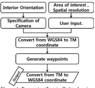
The flight plan computation module generates a flight plan by considering the interior orientation parameters like the focal length, the pixel size, the number of pixels, etc. Figure 6 shows the processing flow in flight planning.
Figure 4. Processing flow in flight planning
For example, let assume that a user specify an area in the
University of Seoul, Korea. The area is about 600 ⅹ 250m². The geospatial resolution is set to 3 cm. By default, the overlap and sidelap ratios are set to 80% and 60%, respectively. The resulted flight plan is shown in Figure 7. The flight plan provides the UAV positions for each image acquisition and the way points partially selected from them. With the change of the resolution, different flight plans can be computed as shown in Table 3.
Figure 5. An example of a flight plan
Spatial
resolution Strip Waypoint
Flight
height Coverage
1cm 19 1102 50m 50ⅹ30m²
2cm 10 270 100m 100ⅹ65 m²
3cm 7 119 150m 150ⅹ100 m²
Table 3. Spatial resolution & Waypoint
3.2.2 Georeferencing: It determines the exterior orientation parameters of each image. Georeferencing is the most important step toward the generation of an orthoimage (Choi, 2012). In this study, we have developed the georeferencing software and show the processing flow in Figure 7. This system is comprised of three processing steps: GPS/INS data integration for position/attitude determination, image matching, and bundle block adjustment. We rapidly calculate the position and attitude of the platform by combining the GPS/INS data through an extended Kalman filter. The image matching process determines the tie-points of the images. Finally, to determine the exterior
orientation for all acquired images, bundle block adjustment is performed using the platform position/attitude and the tie points as the inputs. Actually, the position/attitude are converted to preliminary values for the exterior orientation parameters, to used as the stochastic constraints and initial values for the bundle block adjustment. This software complements the performance of GPS / IMU and acquires a georeferenced image without GCP (Ground Control Point).
Figure 6. Processing flow in georeferencing
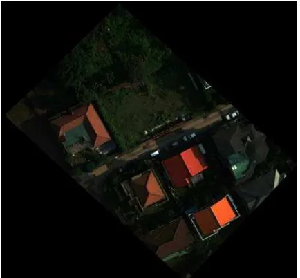
3.2.3 Orthoimage Generation: The UAV acquires central projection images affected by tilt and relief displacement. Orthoimages in which tilt and relief displacement are eliminated, are generated through the process of differential rectification using DEM and exterior orientation parameters precisely determined by the image georeferencing process. Since we produce orthoimages in high-speed, we do not perform dense matching for DEM creation. Instead, we calculate the average elevation of boundary points of the target area and create a constant DEM with the average elevation. By projecting an image to such a flat DEM, we generate a kind of orthoimage. Such an orthoimage is visibly better in spite of the inaccurate positional accuracy. With the test data obtained from the RAMS (Lee, 2011), we generated an orthoimage, as presented in Figure 9. Using the same procedures, we generated 23 orthoimages and combined them to generate a mosaic orthoimage as shown in Figure 9.
Figure 7. Ortho-image
Figure 8. Mosaic ortho-image
3.2.4 Processing Time: Table 4 presents the processing time of the data acquired for 10 minutes by the UAV. The flight planning software computed a flight plan within 0.10 hour including user interaction. The UAV captured 300 images for 10 minutes, and the image size is 6~8MB at an altitude of 50 m above on the ground. The size of all the images is 1800~2400 MBytes. The transmission speed of wireless memory card is 2 megabytes per second. So the data reception software will ideally receive the data within 0.35 hour. And the georeferencing software determines exterior orientation of all images in 0.10 hours. Finally, when ground sample distance (GSD) is 3cm, the orthoimage generation software consumes about 4.60 hours. Considering the flight time, the processing time of the entire procedures is 5.20 hours.
Classification Processing time [Hr]
Language
Flight planning 0.10 C#, MATLAB
Data reception 0.35
Georeferencing 0.10 C++
Orthoimage Generation
4.60 MATLAB
Total 5.15
Hardware
Windows based, core desktop PC(Intel i7) with AMD Radeon HD 6770 graphics card and 8GB of RAM Table 4. Processing time & Hardware Specification
4. CONCLUSION
In this paper, we introduce the overview of our automatic rapid mapping system based on a multi-sensor micro UAV system. This system is composed of aerial and ground segment. The ground segment receives the spatial resolution and the area of interest from the user, and makes an appropriate flight plan. During the UAV flight based on the flight plan, the aerial segment acquires and stores the sensory data for the affected area. Once the UAV completes its flight, the aerial segment will transfer the sensory data to the ground segment. Then, the ground segment rapidly generates the geospatial information such as orthoimage. The results show that we successfully generate the flight plan and produce orthoimages. In future, we will continue more diverse tests and perform more quantitative evaluation on the accuracy. In addition, we will converted most software implemented in MATLAB scripts into those in C++ languages to speed up its process time.
5. ACKNOWLEGEMENT
This work (Grants No. C0018187) was supported by Business for Cooperative R&D between Industry, Academy and Research Institute funded Korea Small and Medium business Administration in 2012.
6. REFERENCES
Smith, J., 1987a. Close range photogrammetry for analyzing distressed trees. Photogrammetria, 42(1), pp. 47-56.
Lazaridou, M. A., and Patmios, E. M. 2011. Photogrammetry and Remote Sensing on the Study of Disasters, Journal of Earth Science and Engineering, 1(3), pp. 14-17.
Choi, K, Lee, J., and Lee, I., 2011. Development of a Close-range Real-time Aerial Monitoring System based on a Low Altitude Unmanned Air Vehicle, Journal of KOREA Spatial Information Society, 19(4), pp. 21-31.
Tralli, D. M., Blom, R. G., Zlotnicki, V., Donnellan, A., and Evans, D. L. 2005. Satellite remote sensing of earthquake, volcano, flood, landslide and coastal inundation hazards. ISPRS Journal of Photogrammetry and Remote Sensing, 59(4), pp. 185-198.
Huggel, C., Kääb, A., Haeberli, W., Teysseire, P., and Paul, F. 2002. Remote sensing based assessment of hazards from glacier lake outbursts: a case study in the Swiss Alps. Canadian Geotechnical Journal, 39(2), pp. 316-330.
Eisenbeiss, H. 2004. A mini unmanned aerial vehicle (UAV): system overview and image acquisition. International Archives of Photogrammetry. Remote Sensing and Spatial Information Sciences, 36(5/W1).
Tahar, K.N and Ahmad, A., 2012. A Novel Method for Photogrammetric Mapping Using UAV Rotary System, LAP LAMBERT Academic Publishing, pp. 38-40.
d'Oleire-Oltmanns, S., Marzolff, I., Peter, K. D., and Ries, J. B. 2012. Unmanned Aerial Vehicle (UAV) for monitoring soil erosion in Morocco. Remote Sensing, 4(11), pp. 3390-3416.
Choi, K., 2012. Real-time Image Georeferencing Using Fast Sequential Bundle Adjustment, Ph. D. Dissertation, University of Seoul, Korea.
Lee, J. Choi, K. and Lee, I., 2011. Developments of a Real-Time Aerial Monitoring System and its Application in Emergency Mapping Teams, International Symposium on Remote Sensing, Yeosu, Korea.
Choi, K., Jihun, L. and Impyeong, L., 2011. A UAV Multi-sensor Mapping System for Disaster Management, Geoinformation for Disaster Management, Antalya, Turkey.
Hernandez-Lopez, D., Felipe-Garcia, B., Gonzales-Agullera, D., and Arias-Perez, B. 2013. An Automatic Approach to UAV Flight Planning and Control for Photogrammetric Applications: A Test Case in the Asturias Region (Spain). Photogrammetric Engineering and Remote Sensing, 79(1).