A GLOBAL SOLUTION TO TOPOLOGICAL RECONSTRUCTION OF BUILDING
ROOF MODELS FROM AIRBORNE LIDAR POINT CLOUDS
Jixing Yana,b, Wanshou Jiangc, Jie Shand,b*
aSchool of Highway, Chang’an University, 710064, Xi’an, China – [email protected] b School of Remote Sensing and Information Engineering, Wuhan University, 430079, Wuhan, China c
State Key Laboratory of Information Engineering in Surveying, Mapping and Remote Sensing, Wuhan University, 430079, Wuhan, China - [email protected]
d Lyles School of Civil Engineering, Purdue University, West Lafayette, IN 47907, USA - [email protected] Commission III, WG III/4
KEY WORDS: Global optimization, Building reconstruction, Roof topology, LiDAR, Point clouds
ABSTRACT:
This paper presents a global solution to building roof topological reconstruction from LiDAR point clouds. Starting with segmented roof planes from building LiDAR points, a BSP (binary space partitioning) algorithm is used to partition the bounding box of the building into volumetric cells, whose geometric features and their topology are simultaneously determined. To resolve the inside/outside labelling problem of cells, a global energy function considering surface visibility and spatial regularization between adjacent cells is constructed and minimized via graph cuts. As a result, the cells are labelled as either inside or outside, where the planar surfaces between the inside and outside form the reconstructed building model. Two LiDAR data sets of Yangjiang (China) and Wuhan University (China) are used in the study. Experimental results show that the completeness of reconstructed roof planes is 87.5%. Comparing with existing data-driven approaches, the proposed approach is global. Roof faces and edges as well as their topology can be determined at one time via minimization of an energy function. Besides, this approach is robust to partial absence of roof planes and tends to reconstruct roof models with visibility-consistent surfaces.
* Corresponding author, [email protected].
1. INTRODUCTION
Automated reconstruction of building roof models is of a current research interest in 3D city modelling. (Airborne) LiDAR (Light Detection and Ranging) technology can directly collect dense, accurate 3D point clouds over building roofs, from which 3D building models may be automatically reconstructed. In spite of many efforts made in the past two decades (Haala and Kada, 2010), building roof reconstruction remains to be an open issue, largely due to the insufficiency of the data and the complexity of the actual building roofs (Xiong et al., 2014).
Various studies on roof model reconstruction from LiDAR point clouds have been reported (Brenner, 2005; Haala and Kada, 2010; Rottensteiner et al., 2014). Among these studies, model-driven methods assume a building is an assembly of roof primitives (e.g., gable roof and hipped roof), which and whose topology are predefined in a model library (Tarsha-Kurdi et al., 2007). To extract roof primitives from LiDAR point clouds, techniques such as invariant moments (Maas and Vosselman, 1999), graph matching (Oude Elberink and Vosselman, 2009; Verma et al., 2006; Xiong et al., 2014), Support Vector Machine (SVM) (Henn et al., 2013; Satari et al., 2012), RANdom SAmple Consensus (RANSAC) (Henn et al., 2013) and Reversible Jump Markov Chain Monte Carlo (RJMCMC) (Huang et al., 2013) are used. However, these approaches tend to fail when reconstructing complex roof shapes. To alleviate this problem, complex roof shapes are usually decomposed into simple ones that are defined in the model library (Kada and McKinley, 2009). Among the reported studies, 2D-plans (Henn et al., 2013; Kada and McKinley, 2009), graph matching technique (Oude Elberink and Vosselman, 2009; Verma et al.,
2006; Xiong et al., 2014) and convexity analysis (Lin et al., 2013) are used for this purpose. Unlike the aforementioned approaches, Huang et al. (2013) extract roof primitives one by one from LiDAR points by using the RJMCMC technique. Although these model-driven approaches could perform well for sparse data, they are limited to roof primitives predefined in the model library. If the roof shape is complex or not predefined in the model library, the model reconstruction may fail (Kim and Shan, 2011).
Among reported studies, the data-driven approaches are more flexible and work well for complex roof models. It is often assumed that a building is a polyhedron consisting of roof planes. Geometric features of a roof model, such as edges and vertices can be determined by the intersection of adjacent roof planes (Perera and Maas, 2014; Sampath and Shan, 2010). As a result, roof model reconstruction is mostly through roof plane extraction from building LiDAR point clouds. A review of these studies can be found in (Yan et al., 2014). The difficulty is to determine the topologic relations among the segmented roof planes (Kim and Shan, 2011). To address this issue, roof topology is described as an adjacency matrix (Sampath and Shan, 2010) or roof topology graph (RTG) (Oude Elberink and Vosselman, 2009; Perera and Maas, 2014; Verma et al., 2006; Xiong et al., 2014), which can be derived from a connectivity analysis of the segmented roof planes. However, the roof topology derived from the aforementioned methods is based on a local decision, i.e., the connectivity analysis is independently carried out for every two or several segmented roof planes. Due to incomplete roof planes arising from occlusion or sparse point clouds, such derived roof topology are likely invalid and inconsistent.
This paper presents a global solution to roof topologic reconstruction from airborne LiDAR point clouds. A binary label optimization approach via graph cuts (Boykov et al., 2001) is used for this purpose. Under this framework, roof features, including roof faces and edges as well as their topology are all determined at one time or globally. Comparing to conventional methods, the proposed approach has two distinctions. First, the topological reconstruction is formulated as an optimization problem, to which a global solution can assure the consistency among all parts of the building and determine roof features at one time. Second, the graph cuts approach is a demonstrated optimization technique, which can fill data gap and create roof models with closed surfaces. The rest of this paper is structured as follows. Section 2 describes the workflow of the approach. Section 3 presents a space partitioning approach using segmented roof planes, in which the bounding box of a building is partitioned into volumetric cells. Section 4 formulates the roof reconstruction task as an inside-outside labelling problem of cells derived from space partitioning, to which a global solution based on graph cuts is presented and roof faces between the inside and outside cells are determined. Results from two data sets are presented and discussed in Section 5. Section 6 presents our concluding remarks.
2. WORKFLOW OF THE APPROACH
This section outlines the workflow of the proposed approach. Once roof planes are segmented from building LiDAR points, the bounding box of the building is recursively partitioned into (volumetric) cells, where roof planes are intersected and possible roof features (e.g., roof faces and edges) as well as their topology can be determined. To look for the correct roof faces and edges, a global energy function is formed and minimized via graph cuts. As a result, the cells are labelled as inside or outside, where the planar surfaces (i.e., roof faces) and edges between the inside and outside cells are the reconstructed roof model.
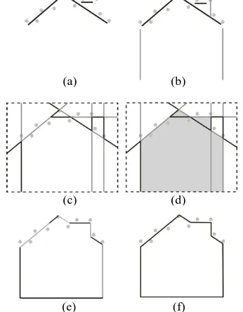
(e) (f)
Figure 1. The workflow of the proposed approach: (a) roof LiDAR points and segmented roof planes (black lines), (b) detected facades (grey lines), (c) cells derived from space partitioning using segmented roof planes and detected facades (dashed rectangle is the bounding box of the building), (d) binary (inside/outside) labelling of cells, where the inside ones are shown in polygons filled with grey, (e) extracted building
surfaces shown in different shades, and (f) roof faces after merging spatially connected building surfaces.
Figure 1 illustrates the workflow of the proposed approach. By using the segmented roof planes and facades derived from building boundary and step edges (Figure 1b), the bounding box of a building is first partitioned into cells (Figure 1c). Then, a binary labelling of these cells is conducted via graph cuts (Figure 1d), and building surfaces which correspond to the faces of reconstructed building model are extracted (Figure 1e). As a result, roof faces and edges as well as their topology are all determined. Finally, spatially connected coplanar roof faces are merged and the roof model is reconstructed (Figure 1f).
Space partitioning is a necessary step for surface reconstruction via graph cuts (Chauve et al., 2010; Oesau et al., 2014). It can reconstructed building are the subset of the volumetric surfaces derived from space partitioning. To reconstruct the roof model resolve this issue, the building boundary and step edges are first extracted, from which facades planes are derived (Perera and Maas, 2014; Sampath and Shan, 2010). In this work, building boundary is traced from roof LiDAR points using a concave hull algorithm (Park and Oh, 2013). As for step edges, they are derived from a height discontinuity analysis (Sohn et al., 2008) of neighbouring roof LiDAR points. Then, an orientation regularization of the detected boundary and step edges is conducted (Zhang et al., 2012). Figure 2 presents an example of this approach. Extracted building boundary and step edges are shown in Figure 2a. They are then regularized with the help of a dominant direction derived from the longest boundary (cf. Figure 2b). Finally, these line features are extruded vertically to create facades as shown in Figure 1b.
(a) (b)
Figure 2. Detected building boundary (outer line segments) and step edges (inner line segments): (a) building boundary and step edges and (b) orientation regularization.
Having extracted building planes, we first construct a cell complex (Damiand, 2015) for the bounding box of the building
(a) (b)
(c) (d)
(cf. Figure 3a). Similar to the half-edge data structure, the cell complex is a B-rep structure to represent topology and geometry. A benefit of such data structure is that it can provide an efficient manipulation of topology in volumes. As shown in Figure 1c, the next step uses a binary space partitioning (BSP) algorithm (Thibault and Naylor, 1987) to partition the bounding box into spatially connected cells. Figure 3 illustrates the procedure of space partitioning with a splitting plane (BSP plane). Benefiting from the cell complex data structure, the topology between derived cells can be preserved (cf. Figure 3d).
(c) (d)
Figure 3. Workflow of space partitioning with a splitting plane: (a) bounding box ABCDEFGH and given splitting plane P; (b) newly generated vertices I, L, J and K; (c) newly generated edges IL, IJ, JK and LK; (d) newly generated face LIJK.
4. ROOF FACES AND THEIR TOPOLOGY
The roof model reconstruction task can be formulated as an optimal inside/outside labelling of cells derived from space partitioning, where the surfaces between inside and outside cells form the reconstructed building model. As shown in Figure 1d, each cell is labelled as inside (i.e., occupied cell) or outside (i.e., empty cell). As a result, the facets corresponding to the edges between occupied and empty cells form a surface of the reconstructed building. Such a binary labelling problem can be formulated as a global energy minimization problem (Chauve et al., 2010; Verdie, 2013), which can be resolved via the min-cut theorem in graph cuts (Boykov et al., 2001).
4.1 Visibility analysis
In this study, the binary labelling problem is noted as a visibility analysis of roof LiDAR points to determine whether a cell is in front of or behind the fitted roof planes. In other words, a cell in front of a roof plane fitted to more LiDAR points is more likely to be visible (i.e., outside cells), whereas a cell behind a roof plane fitted to more LiDAR points is more likely to be invisible (i.e., inside cells).
Figure 4 illustrates the visibility analysis of roof LiDAR points, where 12 cells are derived from the space partitioning step using building planes. Given a LiDAR point p and its fitting roof plane P, a line of sight from an assumed camera center o to the point p is created (i.e., line op). Along this line of sight, the cells behind roof plane P are invisible (e.g., cells 1 and 3), whereas others are visible (e.g., cell 11). As a result, the LiDAR
point p is taken as a point supporting visibility of cell 11, and a point supporting invisibility of cells 1 and 3. For each LiDAR point, this process is conducted. As a result, for each cell c, a visibility vector Xc(a, b) can be derived, where a and b are respectively the number of supporting points of cell visibility and invisibility.
Figure 4. Visibility analysis of cells: the two dark solid lines are the facade planes derived from the building boundary; the dash line is the facade plane derived from step edge; the short dash lines with arrows are the normal directions of corresponding building planes.
4.2 Energy function and minimization
From the visibility analysis of cells, the binary labelling task can be formulated as a minimization of the energy function
( . ) graph and C represents the set of cells. The binary labelling task is to assign a cell p ϵ C a label fp (1 for outside/visible cells and 0 for inside/invisible cells) such that the labelling f minimizes the energy E(f). Two energy terms, i.e., data term (the first term) and regularization term (the second term) are considered in the energy formula. The data term measures the visibility of cells. It is actually the sum of the number of supporting points of cell’s visibility and invisibility. The regularization term measures the label inconsistency between adjacent cells. For each pair of adjacent cells p and q, wpq is the similarity between p and q, and A(p, q) is the area of facet shared by cells p and q. Note that
β is a parameter favouring small area surfaces (Verdie, 2013).
For each cell p ϵ C, ap and bp are respectively the number of for the regularization term, wpq is calculated as
max(min( , ), min( , ), ) problem in Equation 1 can be resolved.
(a) (b)
4.3 Surface extraction and merging
According to the above binary labelling of cells, the surfaces between inside and outside cells are extracted and form an estimated model (cf. Figure 1e). However, roof faces may be partitioned into several planar surfaces in the process of space partitioning. Therefore, spatially connected coplanar roof faces should be merged after surface extraction. As discussed in Section 3, the roof faces and edges as well as their topology have been determined after space partitioning. Based on the spatial connectivity of extracted surfaces, spatially connected coplanar roof faces can be merged (cf. Figure 1f) and the roof model of LiDAR points is reconstructed.
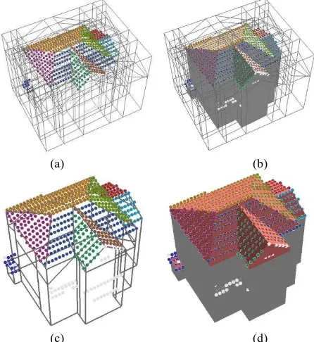
Given segmented roof LiDAR points, Figure 5 illustrates the workflow of roof model reconstruction. Roof and facade planes are first derived and they partittion the building bounding box into cells, where the possible roof faces and edges are determined (Figure 5a). Based on the energy function defined in Equation 1, a binary labeling of cells is conducted. As a result, cells are labled as the outside (empty cells in Figure 5b) and inside (occupied cells in Figure 5b), where the surfaces between inside and outside cells are extracted (Figure 5c). Finally, the spatially connected coplanar surfaces are merged and the estiamted roof model is reconstructed as shown in Figure 5d.
(a) (b)
(c) (d)
Figure 5 Segmented roof LiDAR points and reconstructed model: (a)space partitioning, (b) binary labeling of cells, (c)surface extraction and (d) reconstucted model. Roof point clouds are colored by their planar segments.
5. RESULTS AND DISCUSSION
5.1 Experiments
Two airborne LiDAR data sets over city Yangjiang (China) and Wuhan (China) were used for evaluation. Both of them were captured with a Trimble Harrier 68i system. The test site in Yangjiang (cf. Figure 6a) is located in residential areas with detached houses. Its point density is 2~3pts/m2. The test site in Wuhan (cf. Figure 6b) is seated to the south of Wuhan University and characterized by dense buildings with tree clutter. Its point density is about 5pts/m2.
Roof LiDAR points and their fitted planes are the input for reconstruction. In this study, we use the global optimization approach (Yan et al., 2014) to extract roof planes from roof LiDAR points. Reconstructed roof models are shown in Figure 7. There are 23 buildings in Yangjiang test site and 16 buildings in Wuhan test site. However, due to occlusion from trees, some building boundaries (cf. the building in the rectangular region in Figure 6b) are extremely irregular, which may lead to a wrong regularization of building boundary (cf. the building in the rectangular region in Figure 7b).
(a) (b)
Figure 6. Ortho images of the two test sites: (a)Yangjiang and (b)Wuhan.
(a) (b)
Figure 7 Reconstructed roof models (β = 0.55): (a) Yangjiang and (b)Wuhan.
5.2 Assessment
5.2.1 Reconstruction. To evaluate the performance of our
approach, we compare it with one recently reported model-based graph matching approach (Xiong et al., 2014). Figure 8 illustrates the qualitative evaluation on 8 buildings of Yangjiang (a-d) and Wuhan (e-h) with varying point densities and roof structures. Both approaches perform well with roof LiDAR points and most of the roof planes are successfully reconstructed. However, due to the limitation of roof primitives defined in model library, the graph matching approach may fail when reconstructing complex roof structures. As shown in Figure 8e, the flat roof top visible in the reference image is not reconstructed by the graph-matching method, whereas our global solution yields the right result. Besides, since the topology among adjacent roof planes belonging to different roof primitives is not fully considered, the graph matching approach may fail when assembling roof primitives. Figure 9 further illustrates the situation of Figure 8e. As shown in the rectangular region in Figure 9a, there are two pitched roof ISPRS Annals of the Photogrammetry, Remote Sensing and Spatial Information Sciences, Volume III-3, 2016
primitives on the large flat roof plane, and both of them are successfully reconstructed as shown in Figure 9b and c. However, since the topology between the two pitched roof primitives is not considered, the graph matching approach fails at the intersection of the two roof primitives (cf. the elliptical region in Figure 9b). As for our global approach, the topology between the two pitched roof primitives is well preserved (Figure 9c).
Figure 8. Comparison of roof model reconstruction. From left to right: images, results from the graph matching approach, and results from our global solution. (a-d): Yangjiang, (e-h): Wuhan.
(a) (b) (c)
Figure 9. Topologic reconstruction (Figure 8e) between two roof primitives: (a) image, (b) from the graph matching approach, and (c) from our global approach.
However, the proposed approach is dependent on the completeness of input roof planes. Completeness is the correctly segmented roof planes from roof LiDAR points. Table 1 lists the completeness of reconstructed roof model using our global approach as shown in Figure 8. It is observed in Table 1 that the completeness of segmented roof planes is 92.9%. Most of the roof planes are correctly segmented from roof LiDAR points. As for the reconstructed models, the completeness of reconstructed roof planes is 87.5%, a decrease of 5.4% from the segmentation results and an increase of 6.2% compared to the graph-matching approach. Note that most of the missed planes in the reconstructed buildings are flat roofs whose neighbouring facade planes are missed due to the failure in extracting step edges. As a result, some roof edges and topology cannot be derived from space partitioning. To reconstruct a visibility-consistency surface, minimization of the energy function may get rid of roof planes with incomplete edges. As for the model-based graph matching approach, flat roof planes can be correctly reconstructed even when their neighbouring facade planes are missed (cf. Figure 8c).
Bld ID #Pls %CompA %CompB-1 %CompB-2
a 3 66.7 100 100
b 10 70 90 90
c 11 90.9 81.8 72.7
d 10 90 100 100
e 18 94.4 88.9 88.9
f 8 75 87.5 75
g 19 63.2 94.7 73.7
h 3 100 100 100
Average 81.3 92.9 87.5
Table 1. Completeness of reconstructed roof models. Bld ID: building label (cf. Figure 8); #Pls: the number of reference roof planes; %CompA: the completeness of reconstructed roof planes using the graph matching approach; %CompB-1: the completeness of segmented roof planes; %CompB-2: the completeness of reconstructed roof planes using the proposed global approach.
Figure 10 illustrates the outside/inside labelling of the derived cells when a facade is missed. For example, due to the absence of facade plane F between roof plane A and B, the roof edges determined by the intersection of plane A and F, B and F are missed (Figure 10a). As a result, roof plane A is not reconstructed in Figure 10b. Besides, roof planes may be missed in the segmentation results. Figure 11 illustrates the reconstructed roof models using incomplete roof planes. Although some segmented roof planes are missed, our global approach still outputs a visibility-consistency surface of a building.
(a) (b)
Figure 10. Profile of a reconstruced flat roof: (a) missed facade F and (b) labelled gray cell.
(a)
(b)
(c)
(d)
(e)
(f)
(g)
(h)
missed plane
(a)
(b)
(c)
Figure 11. Reconstructed roof models (building in Figure 8d) from incomplete roof planes. (a)~(c): roof planes in the elliptical areas (left images) are missed.
5.2.2 Parameter sensitivity. Binary labelling problem can
be resolved via various approaches. The advantage of the proposed global approach is that spatial regularization (i.e., the regularization term in Equation 1) of surfaces is considered. To demonstrate this, we first illustrate a reconstructed roof model without considering spatial regularization. As shown in Figure 12, minimization of the energy function makes a hard assignment of labels to cells, which results in a topologically incorrect roof model where its surface is not closed. However, this problem can be well fixed using the proposed approach. As shown in Figure 11 a, b and c, the proposed approach tends to output roof models with closed surfaces even when some roof planes are missed.
Figure 12. Reconstructed building in Figure 8d without considering the regularization term in Equation 1.
The β i Equation 1 is an essential parameter in the global optimization approach. A smaller β results in a building model with large surface area, whereas a larger one produces a building model with small surface area. Figure 13 provides an
example of reconstructed roof models under different β values. As shown in Figure 13a, b and c, the number of planar surfaces derived from reconstructed model decrease with the increase in parameter β. Finally, a cubic building model is created (Figure 13d), and the surface area of the reconstructed model is minimal. From the above discussion, it can be noted that the global approach is able to create the building roof model in different levels of details (LoD). However, the detail of the roof models is sensitive to the value of β, and may not conform to the LoD specification defined in (Gröger et al., 2012).
(a) (b)
(c) (d)
Figure 13. Reconstruced roof model (building in Figure 8d) under different β values: (a) β = 0, (b) β = 0.55, (c) β = 1.0 and (d) β = 1.5.
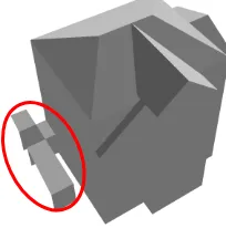
From the above discussion, the proposed approach can determine roof edges and topology without a recursive local connectivity analysis of the segmented roof planes, which can avoid incorrect topology in ambiguous cases. However, the proposed approach is somewhat sensitive to missing building planes, which may in turn miss roof edges in the process of space partitioning. Notably, other factors such as incorrect labelling of cells may also affect the quality of the reconstructed roof model. As shown in Figure 14, due to the lack of sufficient LiDAR points supporting the visibility of derived cells, a narrow small part of the building in the elliptical area is wrongly labelled as outside or visible space.
Figure 14. Building roof model derived from wrong labelling of cells.
6. CONCLUSIONS
This paper presents a global optimization solution to roof topology reconstruction from airborne LiDAR points. Starting from segmented roof planes, the building space is partitioned to possible roof edges with their topology. Then, the roof model is determined by minimizing a global energy function via graph cuts. Results from two sets of airborne LiDAR data sets depict that the completeness of reconstructed roof planes is 87.5%, a slight increase of 6.2% compared to the graph-matching approach.
Compared to the existing reconstruction approaches based on local topology analysis, the proposed approach is a global solution. Roof faces and edges as well as their topology are determined at the same time by minimizing the energy function. This can avoid topologic errors resultant from local connectivity analysis among roof planes. Another property of the proposed approach is that it is robust to incomplete roof planes due to occlusion. Note that the global approach tends to output visibility-consistent building surfaces even using incomplete roof planes. However, it is helpless when the input segmentation result completely misses a plane. Under such a situation, the reconstruction outcome will be erroneous and a model-based solution, e.g., the graph-matching approach, should be considered as a more reliable alternative.
ACKNOWLEDGEMENTS
The authors would like to thank the anonymous reviewers for their valuable comments and suggestions and Dr. Xiong for providing reconstructed roof models from the graph matching approach. This work was partially supported by the National Basic Research Development Program of China (No. 2012CB719904), the National Natural Science Foundation of China (No. 41271431), and the Science and Technology Plan of Sichuan Bureau of Surveying, Mapping and Geoinformation (No. J2014ZC02).
REFERENCES
Boykov, Y., Veksler, O., Zabih, R., 2001. Fast approximate energy minimization via graph cuts. IEEE Transactions on Pattern Analysis and Machine Intelligence 23, 1222-1239. Brenner, C., 2005. Building reconstruction from images and laser scanning. International Journal of Applied Earth Observation and Geoinformation 6, 187-198.
Chauve, A.L., Labatut, P., Pons, J.P., 2010. Robust piecewise-planar 3D reconstruction and completion from large-scale unstructured point data, 2010 IEEE Conference on Computer Vision and Pattern Recognition (CVPR). IEEE, pp. 1261-1268. Chehata, N., Jung, F., Stamon, G., 2009. A graph cut optimization guided by 3D-features for surface height recovery. ISPRS Journal of Photogrammetry and Remote Sensing 64, 193-203.
Damiand, G., 2015. Linear Cell Complex, CGAL User and Reference Manual. CGAL Editorial Board.
Gröger, G., Kolbe, T., Nagel, C., Häfele, K., 2012. OGC city geography markup language (CityGML) encoding standard V2. 0. OGC Doc.
Haala, N., Kada, M., 2010. An update on automatic 3D building reconstruction. ISPRS Journal of Photogrammetry and Remote Sensing 65, 570-580.
Henn, A., Gröger, G., Stroh, V., Plümer, L., 2013. Model driven reconstruction of roofs from sparse LIDAR point clouds. ISPRS Journal of Photogrammetry and Remote Sensing 76, 17-29.
Huang, H., Brenner, C., Sester, M., 2013. A generative statistical approach to automatic 3D building roof reconstruction from laser scanning data. ISPRS Journal of Photogrammetry and Remote Sensing 79, 29-43.
Kada, M., McKinley, L., 2009. 3D building reconstruction from LiDAR based on a cell decomposition approach. International Archives of Photogrammetry, Remote Sensing and Spatial Information Sciences 38, No. 3/W4, pp.47-52.
Kim, K.H., Shan, J., 2011. Building roof modeling from airborne laser scanning data based on level set approach. ISPRS Journal of Photogrammetry and Remote Sensing 66, 484-497. Labatut, P., Pons, J.-P., Keriven, R., 2007. Efficient multi-view reconstruction of large-scale scenes using interest points, delaunay triangulation and graph cuts, Computer Vision, ICCV 2007. IEEE 11th International Conference on. IEEE, pp. 1-8. Labatut, P., Pons, J.P., Keriven, R., 2009. Robust and efficient surface reconstruction from range data, Computer Graphics Forum. Wiley Online Library, pp. 2275-2290.
Lin, H., Gao, J., Zhou, Y., Lu, G., Ye, M., Zhang, C., Liu, L., Yang, R., 2013. Semantic decomposition and reconstruction of residential scenes from LiDAR data. ACM Trans. Graph. 32, 66. Maas, H.-G., Vosselman, G., 1999. Two algorithms for extracting building models from raw laser altimetry data. ISPRS Journal of Photogrammetry and Remote Sensing 54, 153-163. Oesau, S., Lafarge, F., Alliez, P., 2014. Indoor scene reconstruction using feature sensitive primitive extraction and graph-cut. ISPRS Journal of Photogrammetry and Remote Sensing 90, 68-82.
Oude Elberink, S.J., Vosselman, G., 2009. Building Reconstruction by Target Based Graph Matching on Incomplete Laser Data: Analysis and Limitations. Sensors 9(8), 6101-6118. Paris, S., Sillion, F.X., Quan, L., 2006. A surface reconstruction method using global graph cut optimization. International Journal of computer vision 66, 141-161.
Park, J.-S., Oh, S.-J., 2013. A new concave hull algorithm and concaveness measure for n-dimensional datasets. Journal of information science and engineering 29, 379-392.
Perera, G.S.N., Maas, H.-G., 2014. Cycle graph analysis for 3D roof structure modelling: Concepts and performance. ISPRS Journal of Photogrammetry and Remote Sensing 93, 213-226. Rottensteiner, F., Sohn, G., Gerke, M., Wegner, J.D., Breitkopf, U., Jung, J., 2014. Results of the ISPRS benchmark on urban object detection and 3D building reconstruction. ISPRS Journal of Photogrammetry and Remote Sensing 93, 256-271.
Sampath, A., Shan, J., 2010. Segmentation and reconstruction of polyhedral building roofs from aerial lidar point clouds. ISPRS Annals of the Photogrammetry, Remote Sensing and Spatial Information Sciences, Volume III-3, 2016
IEEE Transactions on Geoscience and Remote Sensing 48, 1554-1567.
Satari, M., Samadzadegan, F., Azizi, A., Maas, H.G., 2012. A Multi‐Resolution Hybrid Approach for Building Model Reconstruction from Lidar Data. The Photogrammetric Record 27, 330-359.
Sohn, G., Huang, X., Tao, V., 2008. Using a binary space partitioning tree for reconstructing polyhedral building models from airborne lidar data. Photogrammetric Engineering & Remote Sensing 74, 1425-1438.
Tarsha-Kurdi, F., Landes, T., Grussenmeyer, P., Koehl, M., 2007. Model-driven and data-driven approaches using lidar data: analysis and comparison. International Archives of Photogrammetry, Remote Sensing and Spatial Information Systems, 36(3/W49A), 87-92.
Thibault, W.C., Naylor, B.F., 1987. Set operations on polyhedra using binary space partitioning trees, ACM SIGGRAPH computer graphics. ACM, pp. 153-162.
Verdie, Y., 2013. Urban scene modeling from airborne data. Signal and Image Processing, Université Nice - Sophia Antipolis, Ph.D Thesis.
Verma, V., Kumar, R., Hsu, S., 2006. 3D building detection and modeling from aerial LIDAR data, IEEE Computer Society Conference on Computer Vision and Pattern Recognition. IEEE Computer Society, New York, NY,USA, pp. 2213-2220. Xiong, B., Oude Elberink, S., Vosselman, G., 2014. A graph edit dictionary for correcting errors in roof topology graphs reconstructed from point clouds. ISPRS Journal of Photogrammetry and Remote Sensing 93, 227-242.
Yan, J., Shan, J., Jiang, W., 2014. A global optimization approach to roof segmentation from airborne lidar point clouds. ISPRS Journal of Photogrammetry and Remote Sensing 94, 183-193.
Zhang, Y., Xiong, X., Shen, X., 2012. Automatic registration of urban aerial imagery with airborne LiDAR data. Journal of Remote Sensing 16, 579-595.