HIGH-RESOLUTION MULTISENSOR INFRASTRUCTURE INSPECTION
WITH UNMANNED AIRCRAFT SYSTEMS
C. Eschmann a, *, C.-M. Kuo b, C.-H. Kuo b, C. Boller a,b
a
Fraunhofer Institute for NDT (IZFP), Saarbrücken, Germany - (eschmann, boller)@izfp.fhg.de b
Saarland University, Material Science & Technology Department, Chair in NDT & QA, Saarbrücken, Germany
KEY WORDS: Robotics, Inspection, Monitoring, Infrastructure, Building, Aerial, High resolution
ABSTRACT:
This paper reports on the investigations made at Fraunhofer Institute for Non-Destructive Testing (IZFP) where different rotary wing micro UAS have been used to scan infrastructures including bridges and monuments at high resolutions for remote damage assessment and monitoring purposes. The aerial pictures taken at high speed and frequency have then been stitched together to obtain full 2D and 3D building reconstructions at a resolution allowing damages and cracking to be observed still in the millimeter range. With these ultra hi-res building reconstruction models a specific data base could be created for each object in order to provide extensive information for long term evaluation and life cycle management. The UAS also have been equipped with sensors for damage size estimation, which combined with an image processing software developed to allow automatic cracking pattern recognition could be used for further analysis.
* Corresponding author
1. INTRODUCTION
1.1 Motivation
The inspection of civil infrastructures is a general issue of increasing importance for the construction industry in Germany and the world. In addition, there is an increased demand for new applications for the non-destructive testing (NDT) in order to allow remote inspection and provide a unique monitoring management. Considering the conventional inspection methods already in use for decades brings up the problem between required and actual existing data regarding the condition assessment for infrastructures. Basis for a solid and complete inspection of such objects is a comprehensive data base, which in real case is either poorly or even not existent. This applies in particular for the field of inspection of buildings which are difficult to access, that are distinguished by their exceptional location, size or architecture. It is already evident regarding the objective of a simple inspection of bridges and towers which only could be done by intensive and dangerous assignment of human inspectors while being time consuming and costly. But due to the lack of adequate systems for the collection of such data, such a common inspection remains without appropriate alternative. The technical progress of the last years now opened up new possibilities for the infrastructure inspection by unmanned aircraft. Particularly in the field of the inspection of buildings difficult to access the unmanned aircraft system (UAS) technology comes to the fore. Here they can be used as a flying sensor system to collect the required data with simultaneous reduction in manpower and material costs.
1.2 UAS Applications in NDT
In the field of inspection in terms of the detailed damage assessment of infrastructures, so far there’s only a very limited use of unmanned aircraft, mainly due to the operation in urban
areas and the flying close to obstacles. While the majority of the UAS applications usually takes place at higher altitudes and therefore the critical parameter is only the altitude, these systems mostly are not equipped with appropriate anti-collision sensors and navigation is done based on GPS or by manual control. The approaches shown for inspection tasks so far only reflect the potential of the technology and are not yet commercialized on a large scale for such purposes especially owing to legal safety requirements.
The potential applications for such unmanned aircraft in the non-destructive testing focus on the tasks condition detection, damage analysis and condition monitoring. As a part of the condition detection, the building inspection can be done by numerous NDT methods, as for example visual inspection, thermography, radar or lidar. At the Fraunhofer IZFP, the use of UAS for visual building inspection and remote damage detection is investigated since 2009. For this purpose, the IZFP runs different UAS platforms, which are equipped with various sensors for stabilization and navigation close to objects. Depending on the infrastructure to be inspected and the defined tasks, the UAS can carry different digital optical and thermal cameras for high definition image or video capture.
2. AERIAL SYSTEM
As mentioned before, different UAS platforms are used at Fraunhofer IZFP for aerial infrastructure inspection. Due to the requirements for this kind of application, several multirotor helicopter micro UAS platforms have been investigated and modified. In comparison to a conventional helicopter concept, the technique of multirotor systems offers a very simple mechanism and a highly effective design in terms of different payload concepts. The multi-engine electro-driven platforms therefore can be equipped with various inspection sensors and
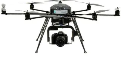
be adapted according to the individual application. Because of their small size, the systems can even be used easily in narrow or urban areas. This is supported by the ability of vertical take-off and landing, accompanied by a steady hovering property which is also a requirement and aim for a punctual and detailed damage assessment. The redundant design of the propulsion also guarantees a controlled return of the system even in case of multiple engine failure. Due to the low total weight of only a few kilograms, even in the event of loss of the aircraft is not a relevant risk for the possibly involved infrastructure. The UAS is equipped with different navigation sensors, stabilized by a microcontroller-based flight control and basically can be operated by GPS waypoint navigation or manual remote control. Figure 1 shows one of the micro UAS platforms used at Fraunhofer IZFP (Kurz, 2012). The concept shown here is an
The octocopter has a size of about 1.2 meters in diameter and a maximum take-off weight of less than 5 kilograms, so it does not exceed German legal weight limitations even with maximum payload. As already said, the octocopter is equipped with various sensors such as three-axis gyroscopes, three-axis accelerometers and a barometric altitude sensor, which are used by a microprocessor-controlled flight control system for attitude stabilization. Together with the sensors of the flight control system and magnetic sensors for 3D orientation, navigation could be done by GPS, but this function is permanently disabled due to reasons mentioned in chapter ‘Infrastructure Inspection’. For safety reasons especially while performing infrastructure inspection in inner cities, the UAS platform – both in manual mode controlled by the pilot as well as in any other semi-autonomous mode – has to be flown within visual line of sight under permanent pilot’s supervision required to intervene at all time. In order to control and to monitor in-flight action, all relevant telemetry data is sent directly to the pilot as well as the ground station, on which the entire flight path planning can be seen. In addition, a real time video image transmission from the UAS is available, either displayed on a laptop or tablet, or otherwise is projected into the pilot’s video eyeglasses in order to get a better picture of the object to be also infrared. The methods mentioned here can be divided into
three main aspects: both the optical and the infrared option – assuming monoscopic operation – offer only a two-dimensional data base under the given inspection parameters, while radar and lidar applications provide important additional depth information for subsequent damage analysis. By contrast to the two previous aspects, the third option of using contact-afflicted ultrasonic measurement, which comes along with the necessary docking of the flight platform to the building structure, is the most unsuitable for a UAS application. Although all of these NDT methods have long been used in a conventional manner in civil engineering, there are numerous constraints regarding their integration in UAS. Since the use of UAS is not yet established in NDT and is only gradually integrated into more and more applications, there are major problems concerning the implementation of available sensors. Due to the fact that sensors usually are designed for ground-based robotic applications, both weight restrictions as well as issues related to power supply and communication of the sensor hardware were of no interest. As a consequence, the range of appropriate sensors is drastically limited while thinking of the integration and operation in a micro UAS. While recent developments in appropriate visual and thermographic cameras increasingly allow such an integration, the implementation of a radar even with modern technical means is hardly feasible.
Whilst these NDT methods listed above are generally applicable for infrastructure inspection by UAS, currently mainly optical methods are used for this purpose. This is based on the fact that in most cases there is not even image data available for a first rapid preliminary damage assessment, so that the need for a purely visual documentation is greatest here. According to this fact and the current flight platforms, building inspections at IZFP are usually conducted by means of visual high-resolution cameras. The cameras often are commercial digital cameras with usable resolutions of 12 to 18 megapixel with focal lengths between 5.0 and 70 millimeters. To provide highest picture quality, the digital zoom function – if available – has been permanently disabled.
3. INFRASTRUCTURE INSPECTION
With regard to the application of infrastructure inspection using UAS, the overall process is generally divided into two process steps: the data acquisition (by aerial survey, in-flight) and the digital post-processing (post-flight).
3.1 Data Acquisition
Concerning aerial infrastructure inspection, the main focus of using UAS is clearly on the data acquisition of the objects to be inspected. To generally fly around an object, a preliminary flight track planning is needed, which is usually done by using a common software based on GPS waypoint navigation. However for inspecting a building GPS navigation becomes insufficient due to the precision required to the façade to be monitored and the threat of any shadowing effects resulting from near by buildings. Moreover standard GPS does not allow accurate flight altitude control which is an essential factor under flight planning aspects. A combination of anti-collision and navigation sensors has therefore to be developed allowing an autonomous flight program (under pilot control) to become feasible in the long term. Hence manual flight control is currently still the only option to perform when flying close to a building.
For the optimization of the post-processing and in order to have the images easily allocated to the real object in a structured way, there are two options of flight pattern available when using an UAS for on-site building inspection. On the one hand, the flight path can be allocated horizontally as a storey-wise scanning of the building (Figure 2). Here, the flight path is characterized by horizontal movements along the building shape at constant altitudes.
Figure 2. Horizontally aligned building flight pattern
On the other hand, the flight path also can follow vertically aligned slices (Figure 3). This option is mainly relevant while thinking of the inspection of towers, monuments and narrow areas of tall buildings. In this case, every image of a single straight trajectory part has the same horizontal coordinates, but differs in vertical coordinates.
Figure 3. Vertically aligned building flight pattern
With regard to the usability of the aerial photos, the flight pattern option 2 was eliminated for most UAS inspection as the main vertical movement increased lens-induced effects negative for stitching. As for the use of flight pattern option 1, which is the preferred one for large building scans, the horizontal speed has to be quite limited while recording images such that fast roll angle changes effecting images are reduced and not be levelled by the automatic stabilization of the camera pod.
For data recording, the integrated digital camera is controlled by an automatic photo-firing sequence, which can be set to a
frequency of up to three pictures per second. Optionally the camera can be controlled manually to set zoom, focus and shutter release if necessary. The flight distance to the inspected building usually is in the range of 2 to 3 meters. Due to this small distance and also sunlight reflections of the building façades, the shutter speed often varies between 1/500 and 1/2000s together with focal lengths between 5 and 16mm. For optimal in-flight detection of damages, both in automatic recording and manual focusing mode, the real-time video link (low definition) can be used by the pilot or another person for camera orientation and for detailed inspections of exposed damaged areas. For this application it is not necessary to transmit also the high quality images in real time, as the digital building reconstruction is still quite time-consuming. Therefore the data stored on the camera is read out after landing. Due to the automatic triggering of the camera, each flight generates a large amount of data, e.g. in a 15 minutes flight normally more than 1200 photos. This amount is far more than what is needed for a subsequent inspection, but as a result of the not completely stable hover a relatively high incidence of unusable image data is produced, a consequence of the not fully filtered out vibrations from the platform or external influences such as wind gusts. Additionally there is a very high overlap of the area captured on each image, which varies depending on the hover speed parallel to the building façade. Accordingly unnecessary records are eliminated in case of too high overlapping to avoid double or multiple information within the images and to keep the image data base as small as possible without loss of quality.
3.2 Image Post-Processing
The second step after completion of the aerial survey is the digital post-processing of the selected images of step 1. Designed for applications such as airborne terrestrial mapping (Remondino, 2011) or panoramic photography (Ward, 2006), there is a variety of experimental and commercial software solutions available to reassemble the individual images nowadays. These stitching or mosaicking methods are based on pattern recognition techniques which analyze similar image content structures, called matching points, in two or more images and link them together based on these points. The panorama creation software (Brown, 2007) analyzes the input data under the assumption that images recorded are made only by pivoting without changing the camera’s position. Since the aerial survey with UAS generates images each made from a slightly different position, the above algorithms are not suitable for this application. In contrast, the software for the mapping of landscape or similar mainly 2D objects can handle images from different locations. However, these algorithms are based on a precise geo-referencing procedure, which is possible due to noticeable GPS location changes together with inertial systems (inertial measurement units, IMU) of high accuracy (Krüger, 2010). Other current software developed from close range photogrammetry, which can also work with little or no initial knowledge of exterior orientation, either focuses on 3D stitching or results in distortion while reconstructing detailed planar objects.
During the investigations, several stitching and mosaicking programs have been analyzed to test their practicability for the reconstruction of building façades. Problems have been found regarding the transition between images, the fact of an unknown geometry of the object to be rebuilt by the software as well as any rearrangement out of image series being available. The stitching of up to 15 images was successful, but to generate a full façade reconstruction consisting of several hundred images
was only possible through stich of the pre-stitched parts hence resulting in a multi-level stitching process. Facing the fact that particularly the edge areas of these façade parts created by the software are currently not suitable for fully automated stitching, stitching work has to be done mainly by hand so far. This is mainly realized by using photoshop programs, with which every single image or image set has to be distorted and resized until it is adapted and integrated in the collage.
4. IMAGE-BASED DIGITAL INSPECTION AND MONITORING
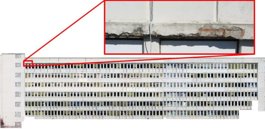
At the end of the whole data acquisition and post-processing procedure there is the aim to obtain a full building façade reconstruction, where the data results in form of ultra-high resolution 2D models can directly be used for digital remote inspection. In order to get such a solid data base for the creation of building reconstructions, huge amounts of image data have to be collected. Once such an image data set is available, it is then used to build a façade reconstruction whose scale is in the gigapixel range. For example for the building shown in Figure 4 more than 12,000 images were taken in-flight, while the final dimensions of the 2D model shown equal only the size of several hundred images due to high overlap. The digital façade reconstruction has an overall resolution of about 1.27 gigapixel. However the full picture size at this resolution is very hard to handle. To make the inspection more user-friendly the model is separated into floors which by themselves are separated into parts of 10 window frames each. Based on this separated data, the inspection then can be done directly on these window sections. In areas of special interest, high resolution detailed photos can be linked to the sections for even better monitoring.
Since the inspection of these building façades only allows a two dimensional evaluation, the individual façade reconstructions for their part are mapped on 3D models. Such a full three-dimensional building model (Figure 5) provides a better orientation and data handling for the inspector, also with respect to secondary inspection criteria such as climate weather side influences at single building parts or installation of additional roof constructions. On the basis of such a model, a section-wise
performed evaluation of the whole building can be done and also the current building condition at a specific date is recorded very accurately. Exactly this digital inspection data later serves as an appropriate documentation basis for monitoring purposes.
Figure 5. High resolution 3D building reconstruction
Since the digital facade reconstructions are created out of huge data sets, a detailed damage detection and characterization can already be done on the basis of the high resolution overall images.
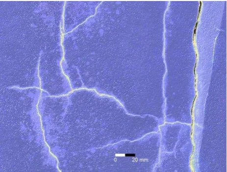
With this data, any part of the building can be enlarged for the exact analysis. In terms of damage inspection, tests have been done based on high resolution areas. The achieved ground resolution is less than 1mm allowing even small cracks to be characterized (Figure 6). Here the aim is finally to have this feature integrated in the full building reconstructions wherever significant damages appear. Therefore some filtering algorithms have been programmed in order to detect cracks automatically.
Due to the high resolution of the image data, even a magnification of the real size of the building is possible, without having an impairment in quality of the inspection. This Figure 4. Ultra-high resolution digital façade reconstruction based on several hundred images
detailed inspection is particularly important for a precise damage assessment and of great interest especially concerning critical areas.
Figure 6. Crack inspection in millimeter range (image solarized)
5. CONCLUSIONS
The method of aerial inspection with unmanned air systems shows that the use of UAS is a suitable means for infrastructure inspection. The technology’s potential of gathering also previously inaccessible data allows the creation of a comprehensive data base required for the monitoring of buildings. Regardless the kind of the integrated inspection sensor, both large-scale and detailed inspections can be performed relatively quickly and easily on the infrastructure scanned with UAS.
By numerous aerial surveys in recent years at various buildings for which digital condition documentations have been created in the form of 2D and 3D models, it has been shown that the optical recording technology allows valuable information about current building conditions. The establishment of visual and thermographic UAS inspection of infrastructures and building sections difficult to access will be a significant improvement in terms of damage detection, damage assessment and efficient restoration planning.
The inspection of infrastructures using aerial survey thus provides a possible basis for new results in studies for condition detection and quality assurance regarding future NDT applications. Regarding further steps, improvements have to be made concerning data acquisition with respect to a better stabilization of the flight platform, anti-collision and navigation systems as well as route planning algorithms to expand the automation of the process. That applies also to the image post-processing by reducing manual workflow by appropriate image stitching and mosaicking software, ideally with an integrated crack detection feature.
ACKNOWLEDGEMENTS
The work presented in this paper was partially funded by the Fraunhofer-Gesellschaft. The authors would like to thank their colleagues and students for their contribution.
REFERENCES
Adams, S., Levitan, M., Friedland, C., 2012. High Resolution Imagery Collection Utilizing Unmanned Aerial Vehicles (UAVs) for Post-Disaster Studies. In: Advances in Hurricane Engineering: Learning from Our Past, pp. 777-793.
Beard, B. L., Jones, K. M., Chacon, C., and Ahumada, A. J., Jr., 2005. Detection of blurred cracks: A step towards an empirical vision standard. In: Final Report for FAA Agreement DTFA-2045.
Brown, M., Hartley, R. and Nister, D., 2007. Minimal Solutions for Panoramic Stitching. International Conference on Computer Vision and Pattern Recognition (CVPR2007), Minneapolis.
Krüger, T., Wilkens, C.-S., Reinhold, M., Selsam, P., Böhm, B., Vörsmann, P., 2010. Ergebnisse des ANDROMEDA-Projektes - Automatische Luftbildgewinnung mit Unbemannten Kleinflugzeugen. Deutscher Luft- und Raumfahrtkongress, Hamburg. Paper ID 161314.
Kurz, J., 2012. Das virtuelle Bauwerk - Kombinierte skalenübergreifende Visualisierung von ZfPBau Ergebnissen. In: Deutsche Gesellschaft für Zerstörungsfreie Prüfung e.V. (DGZfP): Bauwerksdiagnose 2012. DGZfP, Berlin.
Remondino, F., Barazzetti, L., Nex, F., Scaioni, M., Sarazzi, D., 2011. UAV photogrammetry for mapping and 3D modeling - Current status and future perspectives. In: Int. Archives of Photogrammetry, Remote Sensing and Spatial Information Sciences, Vol. 38(1/C22). ISPRS Confernce UAV-g, Zurich, Switzerland
Turner, D., Lucieer, A., Watson, C., 2012. An Automated Technique for Generating Georectified Mosaics from Ultra-High Resolution Unmanned Aerial Vehicle (UAV) Imagery, Based on Structure from Motion (SfM) Point Clouds. Remote Sensing 4, no. 5: 1392-1410.
UVS International. 2012. RPAS: The Global Perspective. 10th ed. Blyenburgh & Co, Paris.
Ward, G., 2006. Hiding seams in high dynamic range panoramas. In: Proceedings of the 3rd symposium on applied perception in graphics and visualization. 153. ACM International Conference Proceeding Series. ACM
Zhang, Y., Xiong, J. Hao, L., 2011. Photogrammetric processing of low-altitude images acquired by unpiloted aerial vehicles. In: The Photogrammetric Record, 26: 190–211.