C++ Unleashed is a survey of advanced topics in C++. The goal of this book is to pro-vide a focused examination of each of these topics, covering the essential information you need to fully exploit the power of the C++ language.
Many of the topics in this book deserve a book in their own right. Because it is not pos-sible, given the available space, to cover every aspect of some of these subjects, the chapters in this book explain only what is most necessary for you to gain a working understanding of the technologies they describe. Often, you will find that the informa-tion provided here is sufficient for your immediate needs. Even if that is not always the case, these chapters provide a useful foundation in these advanced issues that will allow you to quickly gain a more comprehensive understanding of them with further study.
What Is Covered
Part I, “Object-Oriented Programming”
We begin with a comprehensive introduction to object-oriented analysis and design. It is my view that C++ is best used to implement a well-designed object-oriented model, rather than to bang out quick-and-dirty code. The significant advantages of object-orient-ed programming can only be realizobject-orient-ed once you have done the necessary analysis and put the time in to design a well-conceived product. Chapter 1 will get you started on the dif-ficult but rewarding path of object modeling. Along the way, I’ll teach you the funda-mentals of the Unified Modeling Language (UML)—the emerging industry standard. In Chapter 2, you’ll learn how to implement your object model in C++. This mapping, from design model to code, is essential if you want to use C++ to its fullest potential as an object-oriented programming language.
Chapter 3 continues this theme, focusing on how C++ supports inheritance and polymor-phism. This detailed examination of the intricacies of polymorphism will lay the ground-work for creating high-quality commercial C++ applications.
Part II, “Implementation Issues”
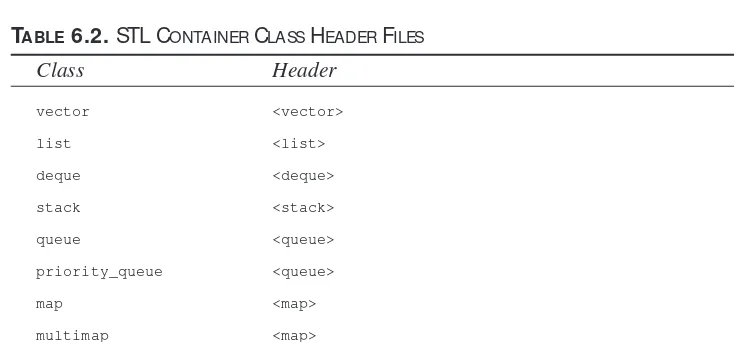
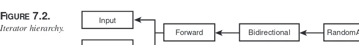
Also in Part II, we’ll offer an in-depth introduction to the Standard Template Library. Chapter 6 focuses on the STL container classes and Chapter 7 follows with a discussion of STL iterators and algorithms. In Chapter 8, we move on to one of the newest features of ANSI C++—namespaces—and we consider how namespaces can help you avoid name clashes as you use third-party libraries.
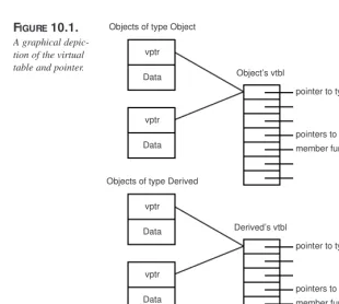
In Chapter 9, we focus on runtime type identification and the new ANSI-style casting operators. Finally, in Chapter 10, we’ll consider how you tune your application perfor-mance to optimize for speed or code size.
Part III, “M anipulating Data”
Part III opens Chapter 11—a discussion of advanced techniques using recursion. In Chapter 12, we discuss sorting algorithms, and in Chapter 13, we discuss object-oriented searching. This discussion is rounded out in Chapter 14 with a consideration of hashing and parsing techniques.
Part IV, “Object Persistence and Encryption”
Chapter 15 considers object persistence and demonstrates how to write your objects to disk and how to manage memory with persistent objects. Chapter 16 returns to the appli-cation frameworks and considers ODBC and MFC Database connections. Chapter 17 extends this discussion to consider object persistence using relational databases, and Chapter 18 discusses object-oriented databases. Finally, in Chapter 19, we discuss encryption including Diffie, Hellerman, Hoffman, and Caesar ciphers; public encryption and popular encryption approaches such as Pretty Good Privacy; and DES and Clipper.Part V, “Distributed Computing Topics”
Chapter 20 considers CORBA, and Chapter 21 provides an in-depth introduction to COM. Finally, Chapter 22 examines the differences between Java and C++ and considers whether these differences are significant.
What You Need To Know Already
C++ Unleashedassumes you have read at least one good primer (such as Sams Teach
Yourself C++ in 21 Days) and/or have been programming in C++ for at least six months.
What Softw are You Need
All of the programs in this book can be created and run with Microsoft Visual C++ or any ANSI-compliant 32-bit compiler. While the example programs in the chapters on the MFC will only compile on a Windows machine (Windows 95 or Windows NT), just about all the other programs in the book will compile on any operating system.
You need no other software—just an editor, compiler, and linker. If you use an integrated development environment such as Visual C++, you are all set. While we’ve endeavored to test all the programs in this book on a number of compilers, we do know that it all works in Microsoft Visual C++, and thus we recommend that compiler if you don’t already have another.
How To Read This Book
Think of this book as a series of “white papers” on advanced topics in C++. Feel free to jump around among the chapters, dipping into those areas which intrigue you. Again, remember that we made no attempt to be “comprehensive” on each topic; rather, our goal was to provide detailed introductions to these advanced topics. Each of these topics is the subject of one or more advanced books. Our goal here is to provide the essential information necessary for you to either start your further study or to obtain a quick and useful overview.
One good way to read this book is as Humpty Dumpty advised: begin at the beginning, proceed to the end, and then stop. As an alternative, you might want to read the first three chapters and then pick and choose among those topics which are of most interest to you.
In any case, enjoy and please let us know how we did. You can reach me, Jesse Liberty, on the Internet at [email protected] is support for the book at the Sams Web site (http://samspublishing.com) as well as at my own Web site
Programming
P
ART
I
I
N
T
HIS
P
ART
• Object-Oriented Analysis and Design 7
• Implementing Class Design in C++ 45
I
N
T
HIS
C
HAPTER
• Building M odels 8
• Softw are Design: The M odeling
Language 9
• Softw are Design: The Process 10
• The Vision 13
• Requirements Analysis 13
• Design 27
1
C
H
A
P
T
E
R
C++ was created as a bridge between \object-oriented programming and C, the world’s most popular programming language for commercial software development. The goal was to provide object-oriented design to a fast, commercial software development platform.
C was developed as a middle ground between high-level business applications languages such as COBOL and the pedal-to-the-metal, high-performance, but difficult-to-use Assembler language. C was to enforce “structured” programming, in which problems were “decomposed” into smaller units of repeatable activities calledprocedures. The programs we’re writing at the end of the 1990s are far more complex than those written at the beginning of the decade. Programs created in procedural languages tend to be difficult to manage, hard to maintain, and impossible to extend. Graphical user inter-faces, the Internet, digital telephony, and a host of new technologies have dramatically increased the complexity of our projects at the very same time that consumer expecta-tions for the quality of the user interface are rising.
In the face of this increasing complexity, developers took a long hard look at the state of the industry. What they found was disheartening, at best. Software was late, broken, defective, bug ridden, unreliable, and expensive. Projects routinely ran over budget and were delivered late to market. The cost of maintaining and building on these projects was prohibitive, and a tremendous amount of money was being wasted.
Object-oriented software development offers a path out of the abyss. Object-oriented pro-gramming languages build a strong link between the data structures and the methods that manipulate that data. More important, in object-oriented programming, you no longer think about data structures and manipulating functions; you think instead about objects. Things.
The world is populated by things: cars, dogs, trees, clouds, flowers. Things. Each thing has characteristics (fast, friendly, brown, puffy, pretty). Most things have behavior (move, bark, grow, rain, wilt). We don’t think about a dog’s data and how we might manipulate it—we think about a dog as a thing in the world, what it is like and what it does.
Building M odels
A child’s globe is a classic model. The model isn’t the thing itself; we would never con-fuse a child’s globe with the Earth, but one maps the other well enough that we can learn about the Earth by studying the globe.
There are, of course, significant simplifications. My daughter’s globe never has rain, floods, globe-quakes and so forth, but I can use her globe to predict how long it will take me to fly from my home to Indianapolis should I ever need to come in and explain myself to the Sams senior management when they ask me why my manuscript was late (“You see, I was doing great, but then I got lost in a metaphor and it took me hours to get out”).
A model that is not simpler than the thing being modeled is not much use. There is a Steven Wright joke about just such a thing: “I have a map on which one inch equals one inch. I live at E5.”
Object-oriented software design is about building good models. It consists of two signifi-cant pieces: a modeling language and a process.
Softw are Design: The M odeling
Language
The modeling languageis the least important aspect of object-oriented analysis and
design; unfortunately, it tends to get the most attention. A modeling language is nothing more than a convention for how we’ll drawour model on paper. We can easily decide that we’ll draw our classes as triangles, and that we’ll draw the inheritance relationship as a dotted line. If so, we might model a geranium as shown in Figure 1.1.
In the figure, you see that a Geranium is a special kind of Flower. If you and I agree to draw our inheritance (generalization/specialization) diagrams like this, we’ll understand each other perfectly. Over time, we’ll probably want to model lots of complex relation-ships, and so we’ll develop our own complicated set of diagramming conventions and rules.
Of course, we’ll need to explain our conventions to everyone else with whom we work, and each new employee or collaborator will have to learn our convention. We may inter-act with other companies that have their own conventions, and we’ll need to allow time to negotiate a common convention and to compensate for the inevitable
misunderstandings.
It would be more convenient if everyone in the industry agreed on a common modeling language. (For that matter, it would be convenient if everyone in the world agreed on a spoken language, but one thing at a time.) The lingua francaof software development is UML—The Unified Modeling Language. The job of the UML is to answer questions like, “How do we draw an inheritance relationship?” The geranium drawing shown in Figure 1.1 would be drawn as shown in Figure 1.2 in UML.
FIGURE1.2.
UML drawing of specialization.
Flower
Geranium
In UML, classes are drawn as rectangles, and inheritance is drawn as a line with an arrowhead. Interestingly, the arrowhead points from the more specialized class to the more general class. The direction of the arrow is counter-intuitive for most folks, but it doesn’t matter much; once we all agree, the system works just fine.
The details of the UML are rather straightforward. The diagrams are not hard to use or understand, and I’ll explain them as we go along in this chapter and throughout the book, rather than trying to teach the UML out of context. Although it is possible to write a whole book on the UML, the truth is that 90 percent of the time, you use only a small subset of the UML notation, and that subset is easily learned.
Softw are Design: The Process
The processof object-oriented analysis and design is far more complex and far more
That is because the debate about modeling languages is pretty much settled; as an indus-try, we’ve decided to use the UML. The debate about process rages on.
A methodologistis someone who develops or studies one or more methods. Typically,
methodologists develop and publish their own methods. A methodis a modeling lan-guage and a process. Three of the leading methodologists and their methods are Grady Booch, who developed the Booch method, Ivar Jacobson, who developed object-oriented software engineering, and James Rumbaugh, who developed Object Modeling
Technology (OMT). These three men have joined together to createObjectory, a method and a commercial product from Rational Software, Inc. All three men are employed at Rational Software, where they are affectionately known as the Three Amigos.
This chapter loosely follows Objectory. I won’t follow it rigidly because I don’t believe in slavish adherence to academic theory—I’m much more interested in shipping product than in adhering to a method. Other methods have something to offer, and I tend to be eclectic, picking up bits and pieces as I go along and stitching them together into a work-able framework.
The process of software design isiterative. That means that as we develop software, we go through the entire process repeatedly as we strive for enhanced understanding of the requirements. The design directs the implementation, but the details uncovered during implementation feed back into the design. Most important, we do not try to develop any sizable project in a single, orderly, straight line; rather, we iterate over pieces of the pro-ject, constantly improving our design and refining our implementation.
Iterative development can be distinguished from waterfall development. In waterfall development, the output from one stage becomes the input to the next, and there is no going back (see Figure 1.3). In a waterfall development process, the requirements are detailed, and the clients sign off (“Yes, this is what I want”); the requirements are then passed on to the designer, set in stone. The designer creates the design (and a wonder to behold it is) and passes it off to the programmer who implements the design. The pro-grammer, in turn, hands the code to a QA person who tests the code and then releases it to the customer. Great in theory, disaster in practice.
In iterative design, the visionary comes up with a concept and then we begin to work on fleshing out the requirements. As we examine the details, the vision may grow and evolve. When we have a good start on the requirements, we begin the design, knowing full well that the questions that arise during design may cause modifications back in the requirements. As we work on design, we begin prototyping and then implementing the product. The issues that arise in development feed back into design, and may even influ-ence our understanding of the requirements. Most important, we design and implement only pieces of the full product, iterating over the design and implementation phases repeatedly.
Although the steps of the process are repeated iteratively, it is nearly impossible to describe them in such a cyclical manner. Therefore, I will describe them in sequence: vision, analysis, design, implementation, testing, rollout. Don’t misunderstand me—in reality, we run through each of these steps many times during the course of the develop-ment of a single product. The iterative design process is just hard to present and under-stand if we cycle through each step; so I’ll describe them one after the other.
Here are the steps of the iterative design process: 1. Conceptualization
2. Analysis 3. Design
4. Implementation 5. Testing
6. Rollout
Conceptualization is the “vision thing.” It is the single sentence that describes the great idea. Analysis is the process of understanding the requirements. Design is the process of creating the model of your classes, from which you will generate your code.
Implementation is writing it in C++; testing is making sure that you did it right, and roll-out is getting it to your customers. Piece of cake. All the rest is details.
C
ONTROVERSIESThe Vision
All great software starts with a vision. One individual has an insight into a product he or she thinks would be good to build. Rarely do committees create compelling visions. The very first phase of object-oriented analysis and design is to capture this vision in a single sentence (or at most, a short paragraph). The vision becomes the guiding principal of development, and the team that comes together to implement the vision ought to refer back to it—and update it if necessary—as it goes forward.
Even if the vision statement comes out of a committee in the marketing department, one person should be designated as the “visionary.” It is his or her job to be the keeper of the sacred light. As you progress, the requirements will evolve. Scheduling and time-to-mar-ket demands may modify what you try to accomplish in the first iteration of the program, but the visionary must keep an eye on the essential idea, to ensure that whatever is pro-duced reflects the core vision with high fidelity. It is this ruthless dedication, this pas-sionate commitment, that sees the project through to completion. If you lose sight of the vision, your product is doomed.
Requirements Analysis
The conceptualization phase, in which the vision is articulated, is very brief. It may be no longer than a flash of insight followed by the time it takes to write down what the visionary has in mind. Often, as the object-oriented expert, you join the project after the vision is already articulated.
Some companies confuse the vision statement with the requirements. A strong vision is necessary, but it is not sufficient. To move on to analysis, you must understand how the product will be used, and how it must perform. The goal of the analysis phase is to artic-ulate and capture these requirements. The outcome of the Analysis phase is the produc-tion of a requirements document. The first secproduc-tion in the requirements document is the use case analysis.
Alt hough t he new sgroups and object -t echnology mailing list s t hrive on split t ing hairs, t he essent ials of object -orient ed analysis and design are f airly st raight f or-w ard. In t his chapt er, I’ll lay out a pract ical approach t o t he process as t he bedrock on w hich you can build t he archit ect ure of your applicat ion. In t he rest of t he book, w e’ll f ocus on t he det ails of implement ing your design in C++.
Use Cases
The driving force in analysis, design, and implementation is the use cases. A use caseis nothing more than a high-level description of how the product will be used. Use cases drive not only the analysis, they drive the design, they help you find the classes, and they are especially important in testing the product.
Creating a robust and comprehensive set of use cases may be the single most important task in analysis. It is here that you depend most heavily on your domain experts; the domain experts have the most information about the business requirements you are trying to capture.
Use cases pay little attention to user interface, and they pay no attention to the internals of the system you are building. Any system or person who interacts with the system is called an actor.
To summarize, here are some definitions:
• Use case:A description of how the software will be used.
• Domain experts:People with expertise in the domain(area) of business for which you are creating the product.
• Actor:Any person or system that interacts with the system you are developing. A use case is a description of the interaction between an actor and the system itself. For purposes of use-case analysis, the system is treated as a “black box.” An actor “sends a message” to the system, and something happens: Information is returned, the state of the system is changed, the spaceship changes direction, whatever.
Identify the Actors
It is important to note that not all actors are people. Systems that interact with the system you are building are also actors. Thus, if we were building an automated teller machine, the customer and the bank clerk can both be actors—as can the mortgage-tracking sys-tem. The essential characteristics of actors are as follows:
• They are external to the system • They interact with the system
For the ATM example just mentioned, we can expect such a list to include the following roles:
• The customer • The bank personnel • A back-office system
• The person who fills the ATM with money and supplies
There is no need to go beyond the obvious list at first. Generating even three or four actors may be enough to get you started on generating use cases. Each of these actors interacts with the system in different ways. We’ll want to capture these interactions in our use cases.
Determine the First Use Cases
Let’s start with the customer role. We might brainstorm the following use cases for a
customer:
• Customer checks his or her balances
• Customer deposits money to his or her account • Customer withdraws money from his or her account • Customer transfers money between accounts • Customer opens an account
• Customer closes an account
Should we distinguish between “Customer deposits money in his or her checking account” and “Customer deposits money in his or her savings account,” or should we combine these actions (as we did in the preceding list) into “Customer deposits money to his or her account?” The answer to this question lies in whether this distinction is mean-ingful in the domain.
To determine whether these actions are one use case or two, you must ask whether the
mechanismsare different (does the customer do something significantly different with
these deposits) and whether the outcomesare different (does the system reply in a differ-ent way). The answer to both questions for the deposit issue is “no”: The customer deposits money to either account in essentially the same way, and the outcome is pretty much the same; the ATM responds by incrementing the balance in the appropriate account.
Given that the actor and the system behave and respond more or less identically, regard-less of whether the deposit is made to the checking or the savings account, these two use
cases are actually a single use case. Later, when we flesh out use-case scenarios, we can try the two variations to see whether they make any difference at all.
As you think about each actor, you may discover additional use cases by asking these questions:
• Why is the actor using this system?
The customer is using the system to get cash, to make a deposit, or to check an account balance.
• What outcome does the actor want from each request? Add cash to an account or get cash to make a purchase.
• What happened to cause the actor to use this system now?
He or she may recently have been paid or may be on the way to make a purchase.
• What must the actor do to use the system? Put an ATM card into the slot in the machine.
Aha! We need a use case for the customer logging in to the system.
• What information must the actor provide to the system? Enter a Personal ID number.
Aha! We need use cases for obtaining and editing the Personal ID number.
• What information does the actor hope to get from the system? Balances, and so on.
You can often can find additional use cases by focusing on the attributes of the objects in the domain. The customer has a name, a PIN, and an account number; do we have use cases to manage these objects? An account has an account number, a balance, and a transaction history; have we captured these elements in the use cases?
Once we’ve explored the customer use cases in detail, the next step in fleshing out the list of use cases is to develop the use cases for each of the other actors. The following list shows a reasonable first set of use cases for the ATM example:
• Customer checks his or her balances
• Customer deposits money to his or her account • Customer withdraws money from his or her account • Customer transfers money between accounts • Customer opens an account
• Customer closes an account
• Customer checks recent transactions
• Bank clerk logs into special management account • Bank clerk makes an adjustment to a customer’s account
• A back-office system updates a user’s account based on external activity • Changes in a user’s account are reflected in a back-office system • The ATM signals it is out of cash to dispense
• The bank technician fills the ATM with cash and supplies
Create the Domain M odel
Once you have a first cut at your use cases, you can begin to flesh out your requirements document with a detailed domain model. The domain modelis a document that captures all you know about the domain (the field of business you are working in). As part of your domain model, you create domain objects that describe all the objects mentioned in your use cases. So far, the ATM example includes these objects: customer, bank personnel, back-office systems, checking account, savings account, and so forth.
For each of these domain objects, we want to capture such essential data as the name of the object (for example, customer, account, and so on), whether or not the object is an actor, the object’s principal attributes and behavior, and so forth. Many modeling tools support capturing this information in “class” descriptions. Figure 1.4 shows how this information is captured with Rational Rose.
1
We can diagram the relationship among the objects in the domain of the ATM example using the UML—with exactly the same diagramming conventions we’ll use later to describe the relationships among classes in the domain. This is one of the great strengths of the UML: We can use the same tools at every stage of the project.
For example, we can capture the fact that checking accounts and savings accounts are both specializations of the more general concept of a bank account by using the UML conventions for classes and generalization relationships, as shown in Figure 1.5.
FIGURE1.5.
Specialization.
Bank Account
Checking Account Savings Account Generalization
Domain object
In the diagram in Figure 1.5, the boxes represent the various domain objects, and the line with an arrowhead indicates generalization. The UML specifies that this line is drawn from the specializedclass to the more general “base” class. Thus, both Checking Account and Savings Account point up to Bank Account, indicating that each is a spe-cialized form of Bank Account.
N
OTEAgain, it is import ant t o not e t hat w hat w e are show ing at t his t ime are rela-t ionships among objecrela-t s in rela-t he domain. Larela-t er, you may decide rela-t o have a CheckingAccountobject in your design, as w ell as a BankAccountobject , and you may implement t his relat ionship using inherit ance, but t hese are design-t ime decisions. Adesign-t analysis design-t ime, all w e are doing is documendesign-t ing our under-st anding of t hese object s in t he domain.
Generalization
Generalization is often equated with “inheritance,” but there is a sharp and meaningful distinction between the two. Generalization describes the relationship; inheritance is the programming implementation of generalization—it is how we manifest generalization in code.
Generalization implies that the derived object is asubtype of the base object. Thus, a checking account is abank account. The relationship is symmetrical: Bank account
gen-eralizesthe common behavior and attributes of checking and savings accounts.
During domain analysis, we seek to capture these relationships as they exist in the real world.
Containment
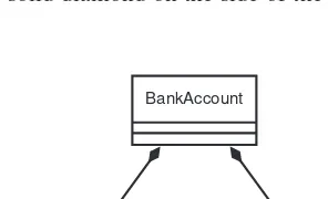
Often, one object is composed of many subobjects. For example, a car is composed of a steering wheel, tires, doors, radio, and so forth. A checking account is composed of a balance, a transaction history, a customer ID, and so on. We say that the checking account hasthese items; containment models the has arelationship. The UML illustrates the containment relationship by drawing a line with a diamond from the containing object to the contained object, as shown in Figure 1.6.
1
FIGURE1.7.
Object relation-ships.
Bank Account
Checking Account Savings Account
Balance Transaction History
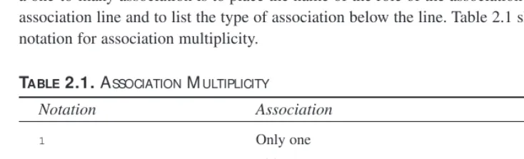
Association
The third relationship commonly captured in the domain analysis is a simple association. An association suggests that two objects know of one another and that the objects inter-act in some way. This definition will become much more precise in the design stage, but for analysis, we are suggesting only that Object A and Object B interact, but that neither contains the other and neither is a specialization of the other. We show this association in the UML with a simple straight line between the objects, as shown in Figure 1.8.
FIGURE1.8.
Association.
Object A Object B
Association
Establish Scenarios
Now that we have a preliminary set of use cases and the tools with which to diagram the relationship among the objects in the domain, we are ready to formalize the use cases and give them more depth.
Each use case can be broken into a series of scenarios. A scenariois a description of a specific set of circumstances that distinguish among the various contingent elements of the use case. For example, the use case “Customer withdraws money from his or her account” might have the following scenarios:
• Customer requests a $300 withdrawal from checking, puts the cash in the cash slot, and the system prints a receipt.
• Customer requests a $300 withdrawal from checking, but his or her balance is $200. Customer is informed that there is not enough cash in the checking account to accomplish the withdrawal.
• Customer requests a $300 withdrawal from checking, but he or she has already withdrawn $100 today and the limit is $300 per day. Customer is informed of the problem, and he or she chooses to withdraw only $200.
• Customer requests a $300 withdrawal from checking, but there is no paper in the receipt roll. Customer is informed of the problem, and he or she chooses to pro-ceed without a receipt.
And so forth. Each scenario explores a variation on the original use case. Often, these variations are exception conditions (not enough money in account, not enough money in machine, and so on). Sometimes, the variations explore nuances of decisions in the use case itself (for example, did the customer want to transfer money before making the withdrawal).
Not every possible scenario must be explored. We are looking for those scenarios that tease out requirements of the system or details of the interaction with the actor.
Establish Guidelines
As part of your methodology, you will want to create guidelines for documenting each scenario. You capture these guidelines in your requirements document. Typically, you’ll want to ensure that each scenario includes the following:
• Preconditions—what must be true for the scenario to begin • Triggers—what causes the scenario to begin
• What actions the actors take
• What results or changes are caused by the system
• What feedback the actors receive
• Whether there are repeating activities, and what causes them to conclude • A description of the logical flow of the scenario
• What causes the scenario to end
• Postconditions—what must be true when the scenario is complete
In addition, you will want to name each use case, and each scenario. Thus, you might have the following situation:
Use Case: Customer withdraws cash
Scenario: Successful cash withdrawal from checking
Preconditions: Customer is already logged in to system
Trigger: Customer requests “withdrawal”
Description: Customer chooses to withdraw cash from a checking account. There is sufficient cash in the account, there is sufficient cash and receipt paper in the ATM, and the network is up and running. The ATM asks the customer to indicate the amount of the withdrawal, and the cus-tomer asks for $300, a legal amount to withdraw at this time. The machine dispenses $300 and prints a receipt, and the customer takes the money and the receipt.
PostConditions: Customer account is debited $300, and customer has $300 cash.
This use case can be shown with the incredibly simple diagram given in Figure 1.9.
FIGURE1.9.
Use case diagram.
Withdraw Cash
Association Customer
Actor
Use Case
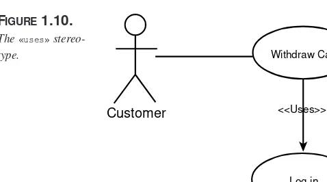
because there are only two interactions possible:«uses»and «extends». The «uses» stereotype indicates that one use case is a superset of another. For example, it isn’t possi-ble to withdraw cashwithout first logging on. We can show this relationship with the diagram shown in Figure 1.10.
1
The «uses»
stereo-type. Withdraw Cash
Customer
Log in <<Uses>>
Figure 1.10 indicates that the Withdraw Cash use case “uses” the Log In use case, and thus fully implements Log In as part of Withdraw Cash.
The «extends»use case was intended to indicate conditional relationships and some-thing akin to inheritance, but there is so much confusion in the object-modeling commu-nity about the distinction between «uses»and «extends»that many developers have simply set aside «extends», feeling that its meaning is not sufficiently well understood. Personally, I use «uses»when I would otherwise copy and paste the entire use case in place, and I use «extends»when I only usethe use case under certain definable conditions.
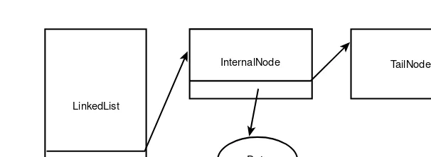
Interaction Diagrams
Although the diagram of the use case itself may be of limited value, there are diagrams you can associate with the use case that can dramatically improve the documentation and understanding of the interactions. For example, we know that the Withdraw Cash sce-nario represents the interactions among the following domain objects: customer, check-ing account, and the user interface. We can document this interaction with an interaction diagram, as shown in Figure 1.11.
This rather simple ATM example shows only a fanciful set of interactions, but nailing down the specifics of these interactions can be a powerful tool in understanding both the problem domain and the requirements of your new system.
Create Packages
Because you generate many use cases for any problem of significant complexity, the UML allows you to group your use cases in packages.
A packageis like a directory or a folder—it is a collection of modeling objects (classes,
actors, and so forth). To manage the complexity of use cases, you can create packages aggregated by whatever characteristics make sense for your problem. Thus, you can aggregate your use cases by account type (everything affecting checking or savings), by credit or debit, by customer type, or by whatever characteristics make sense to you. More important, a single use case can appear in a number of different packages, allowing you great flexibility of design.
Application Analysis
In addition to creating use cases, the requirements document will capture your cus-tomer’s assumptions, constraints, and requirements about hardware and operating FIGURE1.11.
UML interaction diagram.
Customer User-Interface(ATM) Checking Account
1: Request Withdrawal
2: Show options
3: Indicate amount and account
4: Check Balances, status, etc.
5: Return Authorization
6: Debit $300
7: Dispense cash
8: Request receipt
systems. Application requirements are your particularcustomer’s prerequisites—those things that you would normally determine during design and implementation but that your client has decided for you.
The application requirements are often driven by the need to interface with existing (legacy) systems. In this case, understanding what the existing systems do and how they work is an essential component of your analysis.
Ideally, you’ll analyze the problem, design the solution, and then decide which platform and operating system best fits your design. That scenario is as ideal as it is rare. More often, the client has a standing investment in a particular operating system or hardware platform. The client’s business plan depends on your software running on the existing system, and you must capture these requirements early and design accordingly.
Systems Analysis
Some software is written to stand alone, interacting only with the end user. Often, how-ever, you will be called on to interface to an existing system. Systems analysisis the process of collecting all the details of the systems with which you will interact. Will your new system be a server, providing services to the existing system, or will it be a client? Will you be able to negotiate an interface between the systems, or must you adapt to an existing standard? Will the other system be stable, or must you continually hit a moving target?
These and related questions must be answered in the analysis phase, before you begin to design your new system. In addition, you will want to try to capture the constraints and limitations implicit in interacting with the other systems. Will they slow down the responsiveness of your system? Will they put high demands on your new system, con-suming resources and computing time?
Planning Documents
Once you understand what your system must do and how it must behave, it is time to take a first stab at creating a time and budget document. Often, the timeline is dictated, top-down, by the client: “You have 18 months to get this done.” Ideally, you’ll examine the requirements and estimate the time it will take to design and implement the solution. That is the ideal; the practical reality is that most systems come with an imposed time limit and cost limit, and the real trick is to figure out how much of the required function-ality you can build in the allotted time—and at the allotted cost.
• If you are given a range, the outer number is probably optimistic.
• Liberty’s Law states that everything takes longer than you expect—even if you take into account Liberty’s Law.
Given these realities, it is imperative that you prioritize your work. You will not finish—it is that simple. It is important that, when you run out of time, what you have works and is adequate for a first release. If you are building a bridge and run out of time, if you didn’t get a chance to put in the bicycle path, that is too bad; but you can still open the bridge and start collecting tolls. If you run out of time and you’re only half way across the river, that is not as good.
An essential thing to know about planning documents is that they are wrong. This early in the process, it is virtually impossible to offer a reliable estimate of the duration of the project. Once you have the requirements, you can get a good handle on how long the design will take, a fair estimate of how long the implementation will take, and a reason-able guesstimate of the testing time. Then you must allow yourself at least 20 to 25 per-cent “wiggle room,” which you can tighten as you move forward and learn more.
N
OTEThe inclusion of “ w iggle room” in your planning document is not an excuse t o avoid planning document s. It is merely a w arning not t o rely on t hem t oo much early on. As t he project goes f orw ard, you’ll st rengt hen your underst anding of how t he syst em w orks, and your est imat es w ill become increasingly precise.
Visualizations
The final piece of the requirements document is the visualization. The visualization is just a fancy name for the diagrams, pictures, screen shots, prototypes, and any other visu-al representations created to help you think through and design the graphicvisu-al user inter-face of your product.
For many large projects, you may develop a full prototype to help you (and your cus-tomers) understand how the system will behave. On some teams, the prototype becomes the living requirements document; the “real” system is designed to implement the func-tionality demonstrated in the prototype.
Artifacts
are used by the customer to make sure that you understand what the customer needs, by end users to give feedback and guidance to the project, and by the project team to design and implement the code. Many of these documents also provide material crucial both to your documentation team and to Quality Assurance to tell them how the system oughtto behave.
TABLE1.1.ARTIFACTSCREATEDDURING THEANALYSISSTAGE OFPROJECTDEVELOPM ENT
Artifact Description
Use case report A document detailing the use cases, scenarios, stereotypes,
preconditions, postconditions, and visualizations
Domain analysis Document and diagrams describing the relationships
among the domain objects
Analysis collaboration diagrams Collaboration diagrams describing interactions among
objects in the problem domain
Analysis activity diagrams Activity diagrams describing interactions among objects in
the problem domain
Systems analysis Report and diagrams describing low-level and hardware
systems on which the project will be built
Application analysis document Report and diagrams describing the customer’s
require-ments specific to this particular project
Operational constraints report Report describing performance characteristics and
con-straints imposed by this client
Cost and planning document Report with Gantt and Pert charts indicating projected
scheduling, milestones, and costs
Design
Analysis focuses on understanding the problem domain, whereas design focuses on cre-ating the solution. Designis the process of transforming our understanding of the requirements into a model which can be implemented in software. The result of this process is the production of a design document.
The design document is divided into two sections: Class Design and Architectural Mechanisms. The Class Design section, in turn, is divided into static design (which details the various classes and their relationships and characteristics) and dynamic design (which details how the classes interact).
The Architectural Mechanisms section of the design document provides details about how you will implement object persistence, concurrency, a distributed object system, and so forth. The rest of this chapter focuses on the class design aspect of the design docu-ment; other chapters in the rest of this book explain how to implement various architecture mechanisms.
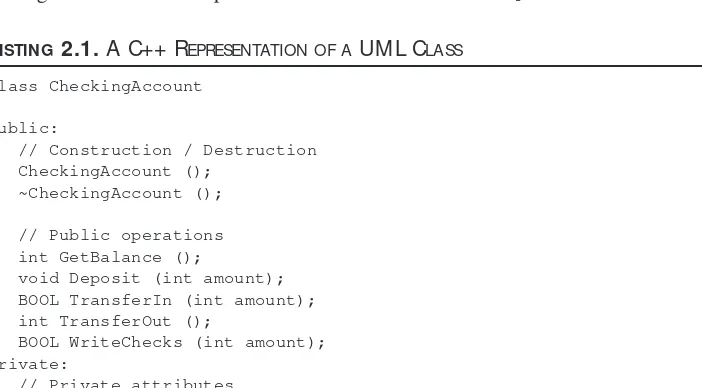
What Are the Classes?
As a C++ programmer, you are used to creating classes. Formal design methodology requires you to separate the C++ class from the design class, though they will be inti-mately related. The C++ class you write in code is the implementation of the class you designed. These are isomorphic: each class in your design will correspond to a class in your code, but don’t confuse one for the other. It is certainly possible to implement your design classes in another language, and the syntaxof the class definitions might be changed.
That said, most of the time we talk about these classes without distinguishing them, because the differences are highly abstract. When you say that in your model your Cat class will have a Meow()method, understand that this means that you will put a Meow() method into your C++ class as well.
You capture the model’s classes in UML diagrams and you capture the C++ classes in code which can be compiled. The distinction is meaningful yet subtle.
In any case, the biggest stumbling block for many novices is finding the initial set of classes and understanding what makes a well-designed class. One simplistic technique suggests writing out the use-case scenarios and then creating a class for every noun. Consider the following use-case scenario:
Customerchooses to withdraw cashfrom checking. There is sufficient cash in the
account, sufficient cash and receiptsin the ATM, and the networkis up and run-ning. The ATM asks the customer to indicate an amountfor the withdrawal, and the customer asks for $300, a legal amount to withdraw at this time. The machine
dispenses $300 and prints a receipt, and the customer takes the moneyand the receipt.
You might pull out of this scenario the following classes: • Customer
• ATM
You might then aggregate the synonyms to create this list, and then create classes for each of these nouns:
• Customer
• Cash (money, amount, withdrawal) • Checking
• Account • Receipts • ATM (machine) • Network
This is not a bad way to start as far as it goes. You might then go on to diagram the obvi-ous relationships among some of these classes as shown in Figure 1.12.
Transformations
What you began to do in the preceding section was not so much to extract the nouns from the scenario as to begin transforming objects from the domain analysis into objects in the design. That is a fine first step. Often, many of the objects in the domain will have
surrogatesin the design. An object is called a surrogate to distinguish between the actual
physical receipt dispensed by an ATM and the object in your design that is merely an intellectual abstraction implemented in code.
You will likely find that mostof the domain objects have an isomorphic representation in the design—that is, there is a one-to-one correspondence between the domain object and the design object. Other times, however, a single domain object is represented in the design by an entire series of design objects. And at times, a series of domain objects may be represented by a single design object.
In Figure 1.11, note that we have already captured the fact that CheckingAccountis a specialization of Account. We didn’t set out to find the generalization relationship, but this one was self-evident, so we captured it. Similarly, we knew, from the domain analy-sis, that the ATMdispenses both Cashand Receipts, so we captured that information immediately in the design.
The relationship between Customerand CheckingAccountis less obvious. We know that there is such a relationship, but the details are not obvious, so we hold off.
Other Transformations
Once you have transformed the domain objects, you can begin to look for other useful design-time objects. A good starting place is with interfaces. Each interface between your new system and any existing (legacy) systems should be encapsulated in an interface class. If you will interact with a database of any type, this is also a good candidate for an interface class.
These interface classes offer encapsulation of the interface protocol and thus shield your code from changes in the other system. Interface classes allow you to change your own design, or to accommodate changes in the design of other systems, without breaking the rest of the code. As long as the two systems continue to support the agreed-on interface, they can move independently of one another.
Data M anipulation
formats for other systems or for transmission over the Internet—in short, any time you must manipulate data into a specified format, you will encapsulate the protocol behind a data manipulation class.
View s
Every “view” or “report” your system generates (or, if you generate many reports, every set of reports) is a candidate for a class. The rules behind the report—both how the infor-mation is gathered and how it is to be displayed—can be productively encapsulated inside a view class.
Devices
If your system interacts with or manipulates devices (such as printers, modems, scanners, and so forth), the specifics of the device protocol ought to be encapsulated in a class. Again, by creating classes for the interface to the device, you can plug in new devices with new protocols and not break any of the rest of your code; just create a new interface class that supports the same interface (or a derived interface), and off you go.
Static M odel
Once you have established your preliminary set of classes, it is time to begin modeling their relationships and interactions. For purposes of clarity, this chapter first explains the static model and then explains the dynamic model. In the actual design process, you will move freely between the static and dynamic model, filling in details of both—and, in fact, adding new classes and sketching them in as you go.
The static model focuses on three areas of concern: responsibilities, attributes, and rela-tionships. The most important of these—and the one you focus on first—is the set of responsibilities for each class. The most important guiding principal is this:Each class
should be responsible for one thing.
That is not to say that each class has only one method. Far from it; many classes will have dozens of methods. But all these methods must be coherent and cohesive; that is, they must all relate to one another and contribute to the class’s ability to accomplish a single area of responsibility.
In a well-designed system, each object is an instance of a well-defined and well-under-stood class that is responsible for one area of concern. Classes typically delegate extrane-ous responsibilities to other, related classes. By creating classes that have only a single area of concern, you promote the creation of highly maintainable code.
To get a handle on the responsibilities of your classes, you may find it beneficial to begin your design work with the use of CRC cards.
CRC Cards
CRC stands for Class, Responsibility, and Collaboration. A CRC card is nothing more than a 4x6 index card. This simple, low-tech device allows you to work with other peo-ple in understanding the primary responsibilities of your initial set of classes. You assem-ble a stack of blank 4x6 index cards and meet around a conference taassem-ble for a series of CRC card sessions.
How to Conduct a CRC Session
Each CRC session should be attended, ideally, by a group of three to six people; any more becomes unwieldy. You should have a facilitator, whose job it is to keep the ses-sion on track and to help the participants capture what they learn. There should be at least one senior software architect, ideally someone with significant experience in object-oriented analysis and design. In addition, you will want to include at least one or two “domain experts” who understand the system requirements and who can provide expert advice in how things ought to work.
The most essential ingredient in a CRC session is the conspicuous absence of managers. This is a creative, free-wheeling session that must be unencumbered by the need to impress one’s boss. The goal here is to explore, to take risks, to tease out the responsibil-ities of the classes and to understand how they might interact with one another.
You begin the CRC session by assembling your group around a conference table, with a small stack of 4x6 index cards. At the top of each CRC card you will write the name of a single class. Draw a line down the center of the card and write Responsibilitieson the left and Collaborationson the right.
Begin by filling out cards for the most important classes you’ve identified. For each card, write a one-sentence or two-sentence definition on the back. You may also capture what other class this class specializes if that is obvious at the time you’re working with the CRC card. Just write Superclass:below the class name and fill in the name of the class this class derives from.
Focus on Responsibilities
The point of the CRC session is to identify the responsibilitiesof each class. Pay little attention to the attributes, capturing only the most essential and obvious attributes as you go. The important work is to identify the responsibilities. If, in fulfilling a responsibility, the class must delegate work to another class, you capture that information under
collab-orations.
various responsibilities listed should be cohesive and coherent—that is, they should work together to accomplish the overall responsibility of the class.
At this point, you do notwant to focus on relationships, nor do you want to worry about the class interface or which methods will be public and which will be private. The focus is only on understanding what each class does.
Anthropomorphic and Use-Case Driven
The key feature of CRC cards is to make them anthropomorphic—that is, you attribute human-like qualities to each class. Here’s how it works: After you have a preliminary set of classes, return to your CRC scenarios. Divide the cards around the table arbitrarily, and walk through the scenario together. For example, let’s return to the following sce-nario:
Customer chooses to withdraw cash from checking. There is sufficient cash in the account, sufficient cash and receipts in the ATM, and the network is up and run-ning. The ATM asks the customer to indicate an amount for the withdrawal, and the customer asks for $300, a legal amount to withdraw at this time. The machine dispenses $300 and prints a receipt, and the customer takes the money and the receipt.
Assume we have five participants in our CRC session: Amy, the facilitator and object-oriented designer; Barry, the lead programmer; Charlie, the client; Dorris, the domain expert; and Ed, a programmer.
Amy holds up a CRC card representing CheckingAccountand says “I tell the customer how much money is available. He asks me to give him $300. I send a message to the penser telling him to give out $300 cash.” Barry holds up his card and says “I’m the dis-penser; I spit out $300 and send Amy a message telling her to decrement her balance by $300. Who do I tell that the machine now has $300 less? Do I keep track of that?” Charlie says, “I think we need an object to keep track of cash in the machine.” Ed says, “No, the dispenser should know how much cash it has; that’s part of being a dispenser.” Amy disagrees: “No, someone has to coordinate the dispensing of cash. The dispenser needs to know if there is cash available and if the customer has enough in the account, and it has to count out the money and know when to close the drawer. It should delegate responsibility for keeping track of cash on hand; some kind of internal account. Whoever knows about cash on hand can also notify the back office when it is time to be refilled. Otherwise, that’s asking the dispenser to do too much.”
The discussion continues. By holding up cards and interacting with one another, the requirements and opportunities to delegate are teased out; each class comes alive, and its responsibilities are clarified. When the group becomes bogged down in design questions, the facilitator can make a decision and help the group move on.
Limitations of CRC Cards
Although CRC cards can be a powerful tool for getting started with design, they have inherent limitations. The first problem is that they don’t scale well. In a very complex project, you can be overwhelmed with CRC cards; just keeping track of them all can be difficult.
CRC cards also don’t capture the interrelationship among classes. Although it is true that collaborations are noted, the nature of the collaboration is not modeled well. Looking at the CRC cards, you can’t tell whether classes aggregate one another, who creates whom, and so forth. CRC cards also don’t capture attributes, so it is difficult to go from CRC cards to code. Most important, CRC cards are static; although you can act out the inter-actions among the classes, the CRC cards themselves do not capture this information. In short, CRC cards are a good start, but you need to move the classes into the UML if you are to build a robust and complete model of your design. Although the transition into the UML is not terribly difficult, it is a one-way street. Once you move your classes into UML diagrams, there is no turning back; you set aside the CRC cards and don’t come back to them. It is simply too difficult to keep the two models synchronized with one another.
Transforming CRC Cards to UM L
Each CRC card can be translated directly into a class modeled with the UML.
Responsibilities are translated into class methods, and whatever attributes you have cap-tured are added as well. The class definition from the back of the card is put into the class documentation. Figure 1.13 shows the relationship between the CheckingAccount CRC card and the UML class created from that card.
Class: CheckingAccount
SuperClass:Account
Responsibilities:
Track current balance
Accept deposits and transfers in Write checks
Transfer cash out
Keep current day’s ATM withdrawal balance
Collaborations:
Class Relationships
After the classes are in the UML, you can begin to turn your attention to the relation-ships among the various classes. The principal relationrelation-ships you’ll model are these:
• Generalization • Association • Aggregation • Composition
The Generalization relationship is implemented in C++ through public inheritance. From a design perspective, however, we focus less on the mechanism and more on the seman-tics: What implies.
We examined the Generalization relationship in the analysis phase, but now we turn our attention not just to the objects in the domain, but also to the objects in our design. Our efforts now are to “factor out” common functionality in related classes into base classes that can encapsulate the shared responsibilities.
When you “factor out” common functionality, you move that functionality out of the spe-cialized classes and up into the more general class. Thus, if I notice that both my check-ing and my savcheck-ings account need methods for transferrcheck-ing money in and out, I’ll move the TransferFunds()method up into the account base class. The more you factor out of the derived classes, the more polymorphic your design will be.
One of the capabilities available in C++, which is not available in Java, ismultiple
inher-itance(although Java has a similar, if limited, capability with its multiple interfaces).
1
Deposit(int amount)() : void TransferIn(int amount)() :bool TransferOut() : intMultiple inheritance allows a class to inherit from more than one base class, bringing in the members and methods of two or more classes.
Experience has shown that you should use multiple inheritance judiciously because it can complicate both your design and the implementation. Many problems initially solved with multiple inheritance are today solved using aggregation. That said, multiple inheri-tance is a powerful tool, and your design may require that a single class specializes the behavior of two or more other classes.
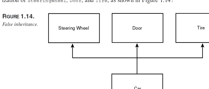
M ultiple Inheritance Versus Containment
Is an object the sum of its parts? Does it make sense to model a Carobject as a special-ization of SteeringWheel,Door, and Tire, as shown in Figure 1.14?
FIGURE1.14.
False inheritance.
Car
Steering Wheel Door Tire
It is important to come back to the fundamentals: Public inheritance should always model generalization. The common expression for this is that inheritance should model is-a relationships. If you want to model the has-a relationship (for example, a car has-a steering wheel), you do so with aggregation, as shown in Figure 1.15.
The diagram in Figure 1.15 indicates that a car has a steering wheel, four wheels, and 2–5 doors. This is a more accurate model of the relationship between a car and its parts. Notice that the diamond in the diagram is not filled in; this is so because we are model-ing this relationship as an aggregation, not as a composition. Composition implies con-trol for the lifetime of the object. Although the car hastires and a door, the tires and door can exist before they are part of the car and can continue to exist after they are no longer part of the car.
created when the body is created and disappear when the body disappears. That is, they have no independent existence; the body is composed of these things and their lifetimes are intertwined.
Steering Wheel Door Tire 1
2..5 4
Discriminators and Pow ertypes
How might you design the classes required to reflect the various model lines of a typical car manufacturer? Suppose that you’ve been hired to design a system for Acme Motors, which currently manufactures five cars: the Pluto (a slow, compact car with a small engine), the Venus (a four-door sedan with a middle-sized engine), the Mars (a sport coupe with the company’s biggest engine, engineered for maximum performance), the Jupiter (a minivan with the same engine as the sports coupe but designed to shift at a lower RPM and to use its power to move its greater weight), and the Earth (a station wagon with a small engine but high RPM).
You might start by creating subtypes of Carthat reflect the various models, and then cre-ate instances of each model as they roll off the assembly line, as shown in Figure 1.17.
FIGURE1.17.
Modeling sub-types.
Car
Earth Jupiter Mars Venus Pluto
How are these models differentiated? As we saw, they are differentiated by the engine size, body type, and performance characteristics. These various discriminating character-istics can be mixed and matched to create various models. We can model this in the UML with thediscriminatorstereotype, as shown in Figure 1.18.
FIGURE1.18.
Modeling the discriminator.
Car
High Power Sedan Coupe Family Car
Low Power Sports Car engine performance
body
The diagram in Figure 1.18 indicates that classes can be derived from Carbased on mix-ing and matchmix-ing three discriminatmix-ing attributes. The size of the engine dictates how powerful the car is, and the performance characteristics indicate how sporty the car is. Thus, you can have a powerful and sporty station wagon, a low-power family sedan, and so forth.
Each attribute can be implemented with a simple enumerator. Thus, the body type might be implemented with the following statement in code:
It may turn out, however, that a simple value is insufficient to model a particular discrim-inator. For example, the performance characteristic may be rather complex. In this case, the discriminator can be modeled as a class, and the discrimination can be encapsulated in an instance of that type.
Thus, the car might model the performance characteristics in a performancetype, which contains information about where the engine shifts and how fast it can turn. The UML stereotype for a class that encapsulates a discriminator, and that can be used to create
instancesof a class (Car) that are logically of different types (for example,SportsCar
versus LuxuryCar) is «powertype». In this case, the Performanceclass is a powertype for car. When you instantiate Car, you also instantiate a Performanceobject, and you associate a given Performanceobject with a given Car, as shown in Figure 1.19.
1
High Power Sedan Coupe Family Car
Low Power Sports Car
engine performance:PerformanceCharacteristics
Powertypes let you create a variety of logicaltypes without using inheritance. You can thus manage a large and complex set of types without the combinatorial explosion you might encounter with inheritance.
Typically, you implementthe powertype in C++ with pointers. In this case, the Carclass holds a pointer to an instance of PerformanceCharacteristicsclass (see Figure 1.20). I’ll leave it as an exercise to the ambitious reader to convert the body and engine discrim-inators into powertypes.
Class Car : public Vehicle {
public: Car(); ~Car();
// other public methods elided private:
PerformanceCharacteristics * pPerformance; };
powertype, these attributes can be parameters to the powertype’s constructor. This means that you can, at runtime, create new typesof cars on-the-fly. That is, by passing different engine sizes and shift points to the powertype, you can effectively create new perfor-mance characteristics. By assigning those characteristics to various cars, you can effec-tively enlarge the set of types of carsat runtime.
FIGURE1.20.
The relationship between aCar
object and its powertype.
Car
High Power Sedan Coupe
Low Power
engine
body
Performance Characteristics
shift Point max RPM accelerate
Dynamic M odel
In addition to modeling the relationships among the classes, it is critical to model how they interact. For example, the CheckingAccount,ATM, and Receiptclasses may interact with the Customerin fulfilling the “Withdraw Cash” use case. We return to the kinds of sequence diagrams first used in analysis, but now flesh out the details based on the meth-ods we’ve developed in the classes, as shown in Figure 1.21.
This simple interaction diagram shows the interaction among a number of design classes over time. It suggests that the ATMclass will delegate to the CheckingAccountclass all responsibility for managing the balance, while the CheckingAccountwill call on the ATM to manage display to the user.
Interaction diagrams comes in two flavors. The one in Figure 1.20 is called a sequence
diagram. Another view on the same information is provided by the collaboration
1
As we come to understand the interactions among the objects, we have to understand the various possible statesof each individual object. We can model the transitions among the various states in a state diagram (or state transition diagram). Figure 1.23 shows the vari-ous states of the CustomerAccountclass as the customer logs into the system.
FIGURE1.21.
Sequence diagram.
Customer ATM Checking Account
1: Check Balances
2: Get Balance
3: Display Balance
6: Print 4 : Withdraw cash
5 : Dispense 4 : Withdraw cash
5 : Dispense
Every state diagram begins with a single startstate and ends with zero or more endstates. The individual states are named, and the transitions may be labeled. The guardindicates a condition that must be satisfied for an object to move from one state to another.
Super States
The customer can change his mind at any time and decide not to log in. He can do this after he swipes his card to identify his account or after he enters his password. In either case, the system must accept his request to cancel and return to the “not logged in state” (see Figure 1.24).
As you can see, in a more complicated diagram, the Canceledstate quickly becomes a distraction. This is particularly annoying because canceling is an exceptional condition that should not be given prominence in the diagram. We can simplify this diagram by using a super state, as shown in Figure 1.25.
The diagram in Figure 1.24 provides the same information in Figure 1.23 but is much cleaner and easier to read. From the time you start logging in until the system finalizes your login, you can cancel the process. If you do cancel, you return to the state “not logged in.”
FIGURE1.23.
Customer account state.
Getting Account Info
Getting Password Not Logged In
Logged In
Solid bullet = start
State transition
State
Guard
1
O
B
JE
C
T
-O
R
IE
N
T
E
D
A
N
A
LY
S
IS
A
N
D
D
E
S
IG
N
Summary
This chapter provided an introduction to the issues involved in object-oriented analysis and design. The essence of this approach is to analyze how your system will be used (use cases) and how it must perform, and then to design the classes and model their relation-ships and interactions.
FIGURE1.24.
User may cancel.
Getting Account Info
Getting Password Not Logged In
Logged In Start
Canceled Canceled
FIGURE1.25.
Super state.
Not Logged In
Logged In Start
Getting Password Getting Account Info Canceled
In the old days, we sketched out a quick idea of what we wanted to accomplish and began writing code. The problem is that complex projects are never finished; and if they are finished, they are unreliable and brittle. By investing up front in understanding the requirements and modeling the design, we ensure a finished product that is correct (that is, it meets the design) and that is robust, reliable, and extensible.
I
N
T
HIS
C
HAPTER
• Translating Class Diagrams into C++ 42
• Translating Interaction Diagrams
into C++ 61
• Translating State Transition Diagrams
into C++ 68
• Translating Activity Diagrams
into C++ 72