Solar Powered Exhaust Fan for Automobiles
by
Azlia Binti Ajid
Dissertation submitted in partial fulfilment of the requirements for the
Bachelor of Engineering (Hons) (Mechanical Engineering)
DECEMBER 2008
Universiti Teknologi PE1RONAS Bandar Seri Iskandar
31750 Tronoh
Perak Darul Ridzuan
CERTIFICATION OF APPROVAL
Solar Powered Exhaust Fan for Automobiles
Approved by,
(How Meng Git)
By
Azlia Binti Ajid
A project dissertation submitted to the Mechanical Engineering Department
Universiti Teknologi PETRONAS in partial fulfilment of the requirements for the
BACHELOR OF ENGINEERING (Hons) (MECHANICAL ENGINEERING)
UNIVERSITI TEKNOLOGI PETRONAS TRONOH, PERAK
December 2008
CERTIFICATION OF ORIGINALITY
This is to certifY that I am responsible for the work submitted in this project, that the original work is except as specified in the references and acknowledgements, and that the original work contained herein have not been taken or done by unspecified sources or persons.
ACKNOWLEDGEMENT
Throughout the completion of this Final Year Project (FYP), many people have give a great support, guidance, advice, assistance and brilliant ideas to me. Without their help, this FYP would not be successful as it is now. Therefore, I would like to take this opportunity to thanks as a symbol of my appreciation to all who had contributed a lot in my learning and excellence in this FYP.
First of all I would like to express my gratitude to God Almighty for His blessings that help me smoothly complete my FYP for this whole year.
My highest and heartiest appreciation is for my supervisor, Ms How Meng Git for providing me with the enormous idea of the Solar Powered Exhaust Fan for Automobiles and guiding me throughout the project. Certainly this project wouldn't be a success without her priceless advices, guidance and sincere attention.
I also like to thank the staffs of Production Engineering Engine, Transmission and Machining for their guidance and information for this project. Furthermore, thanks to Mr Daud, Electronic teacher from Sekolah Menengah Teknik Bandar Sri Iskandar for his support, help throught the project.
Lat but not least, I would also like to extend my gratitude to my dad, for his truly support and help in the early of this FYP till the ends, Mr. Amin from ACK Auto service and my friend, Mr. Norhafiz Nordin for their ideas and assistance at various occasions during the project.
ABSTRACT
Long exposure of a vehicle to hot weather at an open space parking will cause an extreme heat build-up in the car cabin. This extreme heat build-up will increase the interior temperature of vehicle's cabin which cause uncomfortable situation to most people, especially when they get into their car. The effect that most of us do not realize is that this situation will be hazardous to human health and is one of the major causes of heat illnesses. In order to reduce the high temperature to at least near the ambient temperature before driver gets into their vehicle, this project will utilize solar energy that is converted to electrical energy to initiate the fan inside the system. The system also includes rechargrable battery to activate the fan if there is insufficient energy from solar
f
panel. A relay. concept is used for the switching process and the fan will only activate if the thermostat detect certain level of temperature. The project scope involved are
' (
studying the negative impact of extreme heat build-up to human health, conducting a survey to 100 of Universiti Teknologi PETRONAS (UTP) students, analyzing current product's strengths and weaknesses, designing and fabricating operating exhaust fan and lastly, validate product by comparing result between sample car with Solar Powered Exhaust Fan for Automobiles and sample car without the product. The project is conducted by do the literature review and research, collect data for temperature distribution in three different volume of cars, produce engineering design specifications, generate conceptual design, analyze and evaluate alternatives design, finalized design by producing technical drawing and specifications, construct the prototype and finally, validate the final product. This solar powered exhaust fan ensures that the engine is not overburdened and increases its service life, conserving energy, protecting the environment while creating a comfortable traveling environment.
TABLE OF CONTENTS
ABBREVIATIONS AND NOMENCLATURES ... 1
CHAPTER 1: INTRODUCTION ... 2
1.1 Background of Study ... 2
1.2 Problem Statement ... 2
1.3 Objective and Scope of Study ... 4
CHAPTER 2: LITERATURE REVIEW ... 6
2.1 Solar Energy and Its Application ... 6
2.2 Solar Electricity (Low Power Application of Photovoltaic) ... 7
2.3 Existing Products in the Market ... 9
2.4 Related Research on Reducing Interior Temperature By Ventilating Air in Enclosed Area of A Car ... II CHAPTER 3: THOERY ... 15
3 .1 Heat Quantity ... 15
3.2 Electric Work Required ... 17
CHAPTER 4: METHODOLOGY ... 18
4.1 Project Work Flow ... 18
4.1.1 Literature Review ... 18
4.1.2 Data Gathering ... 20
4.1.2.1 Collection of Temperature Data in Enclosed Area of Car ... 20
4.1.2.2 Analysis of Current Products ... 20
4.1.2.3 Distribution of Survey ... 21
4.1.3 Designing ... 21
4.1.3.1 Details on Engineering Design Specifications ... 22
4.1.3.2 Generating Conceptual Design ... 22
4.1.3.3 Analyzing and Evaluating Alternatives ... 22
4.1.3.4 Producing Technical Drawing and Specification ... 23
4.1.4 Fabrication of Prototype ... 23
4.1.5 Validation of Design ... 23
CHAPTER 5: RESULT AND DISCUSSION ... 24
5.1 Mechanism of Solar Powered Exhaust Fan for Automobiles ... 24
5.2 Electric Power Required by the System from Mathematical Model... ... 25
5.3 Selection of Materials I Components ... 29
5.3.1 Alternatives of Exhaust Fan Power Supply ... 29
5.3.2 Alternatives of Exhaust Fan ... 30
5.4 Engineering Design Specification (EDS) ... 31
5.5 Bill of Material ... 32
5.6 Detailed Design of Solar Powered Exhaust Fan for Automobiles ... 33
5.7 Product Validation ... 39
CHAPTER 6: CONCLUSION ... 42
CHAPTER 7: RECOMMENDATION ... 44
REFERENCES ... 45
APPENDICES ... 46
LIST OF FIGURES
Figure 1.1 Temperature Difference
between Car Cabin and Ambient Temperature 3
Figure 2.1 Cross-Section ofPhotovoltaic Cells 7
Figure 2.2 Production of Photo-electrons 8
Figure 2.3 Solar Cell Configuration 9
Figure 2.4 Trillium Worldwide TWI-7001 Auto Vent Solar-Powered Ventilator 10
Figure 2.5 Auto Cool Solar Powered Fan 10
Figure 2.6 Solar-Powered Auto Vent Turbo Fan 10
Figure 2.7 Mechanism of
Intelligent Solar-Powered Automobile-Ventilation System 12 Figure 2.8 Circuit Diagram of
Intelligent Solar-Powered Automobile-Ventilation System 12 Figure 2.9 Perspective View of
Portion of a Car where Invention is Applied 13
Figure 2.10 Sectional View of
A Vehicle's Body along a Center Line of Exhaust Path 14
Figure 3.1 Illustration on Dimension of Car Cabin 16
Figure 3.2 Assumption on Design of Vehicle's Cabin 16
Figure 4.1 Project Work Flow Chart 19
Figure 4.2 Data Collection Flow Chart 21
Figure 4.3 Validation of Design Work Flow 23
Figure 5.1 Process Flow of Solar Powered Exhaust Fan for Automobiles 25 Figure 5.2 Graph for Ambient Temperature
and Car's Interior Temperature for PROTON Wira 26 Figure 5.3 Top View of Prototype Attaches
to Board at Rear Shelf-Board of a Car 33
Figure 5.4 Actual Top View of Prototype Attaches
to Board at Rear Shelf-Board of a Car 34
Figure 5.5 Technical Drawing
of Solar Powered Exhaust Fan for Automobiles Casing 35
Figure 5.6 Connection of Solar Panel in Series 36
Figure 5.7 Drawing of Exhaust Hose 36
Figure 5.8 Picture of Exhaust Hose 37
Figure 5.9 Technical Drawing of
Solar Powered Exhaust Fan for Automobiles without Solar Panel 38 Figure 5.10 Graph shows Temperature Difference from Product Validation 41
LIST OF TABLES
Table 2.1 Bulk and Thin-Film Type ofPV cell 8
Table 5.1 Ambient Temperature and Car's Interior Temperature
Data for Wira Aero back 26
Table 5.2 Heat Quantity, Electric Work and
Power Required at Each Hour during Data Collection 29 Table 5.3 Alternatives of Power Supply to the Exhaust Fan 30
Table 5.4 Alternatives of Exhaust Fan 30
Table 5.5 Technical Specifications of Solar Powered Exhaust Fan
for Automobiles 31
Table 5.6 Build of Material of Solar Powered Exhaust Fan
for Automobiles 32
Table 5.7 Data Collection on Product Validation 40
ABBREVIATIONS AND NOMENCLATURES
FYP
=
Final Year ProjectUTP
=
Universiti Teknologi PETRONAS T.,=
Ambient Temperature (0C)p
=
Density (g/cm3)oc
=
Degree Celcius$
=
US DollarRM
=
Ringgit Malaysia Vc=
Voltage (V)v =
Volume (cm3)=
Length (em)w
=
Width (em)h
=
Height (em)Qh
=
Heat Quantity (J)Pa Density of Air (0.0012g/cm3)
Ca
=
Specific heat of air (1.0048 J/ go C) T Temperature ("C)t
=
Time (s)w. =
Electric Work (kJ) I Current required (A)p Power(W)
TR Temperature Reduction(%) Tbase Baseline Temperature ("C)
CHAPTERl 1.0 INTRODUCTION
1.1 Background of Study
This project is related to a ventilation process of air in an enclosed area that allows the hot air to be replaced by fresh air from the outside. The research focused on studying a ventilating device for automobiles which prevents temperature in the cabin of a vehicle from going too high during the vehicle's parking time. Particularly, it relates to a ventilating system where a solar panel will be used to convert the sun light to electrical energy that activates the fan to remove the hot air inside the vehicle.
1.2 Problem Statement
Most of the parking lots or areas in Malaysia are under the direct sunlight especially parking lots in most universities in Malaysia. For example, student's parking lots for each department in Universiti Kebangsaan Malaysia (UKM), and student village parking lots in Universiti Teknologi PETRONAS (UTP). This kind of hot weather with temperature range from 32
oc
to 34oc
[I] will cause the interior temperature of a vehicle to increase and will keep increasing depending on how long the automobile is being parked there.The heat source of the automobiles is the heat from sun light that gets through the glass window by radiation. The glass window of car that has high heat capacity and low thermal conductivity does not allow the interior heat energy to pass through as easy as light, thus, some heat will be trapped in the enclosed area of car cabin causing the interior temperature to increase [2].
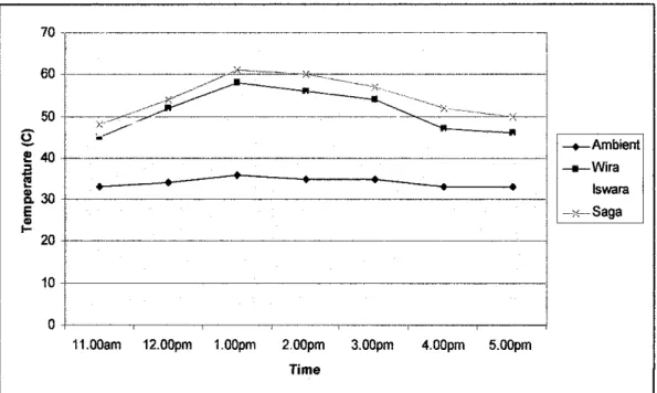
One preliminary data collection had been conducted to prove that the interior temperature in the car cabin is high which is exceeding 40
oc
during hot weather day asshown in Figure 1.1. The experiment was conducted in one of open space parking lot in UTP, P7 parking lot, by using 3 different volume of car. Figure 1.1 shows the high difference of interior temperature in the cars compared to ambient temperature.
60 1--~~~--~--;~----?·-!= .. ·=·----'A~~"'7-::::::::-:==~;-_·_---
\I
50~-:;~/~ -~---~--= - 2'==~,f----~
'--+---cA-mccbie-ntCle 40 ----~---~
~
8. 30 +---·~~-~~--!
:: +--~--~~-======----=---=--====~=~-=~·======~~~=~-·
0+---~--~--~--,---~--~--~
11.00am 12.00pm 1~00pm 2.00pm 3.00pm 4.00pm 5.00pm Time
----wira lswara ->c--Saga
Figure 1.1: Temperature Difference between Car Cabin and Ambient Temperature.
The heat is reflected inside the car and some been absorbed by the seats, dashboard, steering, transmission case, handbrake case and etc which causes the increase of heat amount inside the cabin. As a result, the air in the enclosed area inside vehicle becomes stale and uncomfortable because there is no air circulation in the enclosed area of car cabin.
The parts in the vehicle like instrumentation panel, leather seats and plastic accessories, age rapidly if exposed to extreme heat built-up situation for a long period [3]. High interior temperature can be reduced by removing the hot air within an automobile through opening a door or car glass window, activating the engine and turning the air conditioning to its peak power after entering a car. However, all these processes take some time to reduce the interior temperature to a comfortable level. Furthermore, if the engine has not reached a proper working temperature when the air conditioner is turned on, then the additional loading that occur will lead to speedy abrasion of
The effect that most of us do not realize is the situation will be hazardous to human health. Our bodies create a tremendous amount of internal heat. We normally cool ourselves by sweating and radiating heat through our skin. Under certain circumstances, such as unusually high temperatures, high humidity in hot weather and enclosed area, this natural cooling system may begin to fail, allowing internal heat to build up to dangerous level. The example of hazard that might affect our body and health when dealing with this situation are heat illness, which can come in two forms which are heat exhaustion, or heatstroke [4).
Examples of heat exhaustion are headache, dehydration and hyper ventilation which result in rapid breathing. Heatstroke is the most serious form of heat illness that needs immediate medical treatment. When heatstroke occurs, human body loses its ability to regulate its own temperature. Body temperature can rise to 106 op ( 41.1 oq or even higher, leading to brain damage or even death if it isn't quickly treated. Heatstroke is more hazardous to the children than adults. There are many cases of heatstroke involving children where a child is left in, or becomes accidentally trapped in a car on a hot day. When the outside temperature is 93 °F (33.9 °C}, the temperature inside a car can reach 125 op (51.7 °C) in just 20 minutes, quickly raising a child's body temperature to dangerous levels [4].
1.3 Objective and Scope of Study
The objective of this project is to design a solar powered exhaust fan for automobiles that ventilates continuously after it reach certain level of temperature to reduce the interior vehicle temperature to the ambient temperature.
The project scope involved is given as follows:
a) Study of negative health impact due to exposure to extreme temperature in an enclosed area.
b) Conducting a survey to I 00 of students in UTP about how they react to the high temperature when entering a car.
c) Study of existing products in the market by analyzing their strengths and weaknesses.
d) Design and fabricate a device which is able to operate that based on the research completed.
e) Product validation by comparing the result between sample car with solar powered exhaust fan and sample car without the product.
CHAPTER2
2.0 LITERATURE REVIEW
This chapter presents all relevant information and data that are useful for the designing of Solar Powered Exhaust for Automobiles. This chapter also explains the related researches that are relevant to support this project. The researches that have been gathered are:
• Solar Energy and Its Application
• Solar Electricity (Low Power Application ofPhotovoltaic)
• Existing Products in the Market
• Related Research on Reducing Interior Temperature by Ventilating Air in Enclosed Area of A Car
2.1 Solar Energy and Its Application
Solar energy from direct sun light is radiation where most technologies capture this radiation as heat. Heat and light from the sun, along with other energy resources such as wind and wave power account for most of the available flow of renewable energy [5].
There are many examples for application of solar energy in the world. For instance, the most common use of solar energy is as day lighting where the visible solar radiation been used to reduce or eliminate the need of artificial lighting in a building. Other than that, solar energy is used for application of active heating like in Alaska to provide domestic hot water and passive heating for space heating by moving the heat through conduction, convection and radiation [6].
Solar energy also can be directly converted to electrical energy. It was first explored for electrical purposes in the 1950s, when the need for continuous electric power generation on space satellites spawned the development of a solar cell in the Bell Telephone Laboratories of the United States [7]. The solar energy can be converted to electrical
energy either through the photovoltaic effect by using solar panel or photovoltaic cells, or by heating a transfer fluid to produce steam to run a generator [5]. In this project, solar energy will be used to generate electricity that initiates the fans.
2.2 Solar Electricity (Low Power Application of Photovoltaic)
Photovoltaic power generation is reliable, involves no moving parts, and the operation and maintenance cost are very low. The operation of a photovoltaic system is silent and
creates no atmospheric pollution. Photovoltaic systems are modular and can be quickly installed. Power can be generated where it is required without the need of transmission line. The solar cell operation in photovoltaic system is based on the ability of semiconductor to convert sunlight directly into electricity by exploiting the photovoltaic
effect. In the conversion process, the incident energy of light creates mobile charged particles in the semiconductor which are the separated by the device structure and produce electrical current [8].
external load
antl-reflec1JVe coating
D
) front & back contact•..---
P·tvpen-type
Figure 2.1: Cross-Section ofPhotovoltaic Cell [9]
This concept can be further explained by using the photoelectric effect concept.
Figure 2.2 shows the basic concept of production of photo-electrons that generate electricity in photovoltaic cells [ 1 0].
incident light
ejected electrons
I ~/
MetalI
Figure 2.2: Production of photo-electrons [ l 0]
Figure 2.2 shows that when light falls on metal surface, electrons may be ejected. The amount of current generated by photon excitation in a Photovoltaic cell is affected by
incident light in two ways:
• By the intensity of the incident light.
• By the wavelength of the incident rays.
Photovoltaic cells are most commonly made of silicon, and come in two varieties, bulk and thin-film type, as detailed in Table 2.1.
Table 2.1:
Bulk and Thin-Film Type of PV Cell [9]
Cons
Able to automate all Can be more efficient man
Cons
The materials used in PV cells have different spectral responses to incident light, and exhibit a varying sensitivity with respect to the absorption of photons at given wavelengths. Each semiconductor material will have an incident radiation threshold
frequency, below which no electrons will be subjected to the photovoltaic effect. Above the threshold frequency, the kinetic energy of the emitted photoelectron varies according to the wavelength of the incident radiation, but has no relation to the light intensity.
Increasing light intensity will proportionally increase the rate of photoelectron emission in the photovoltaic material. In actual applications, the light absorbed by a solar cell will be a combination of direct solar radiation, as well as diffuse light bounced off of surrounding surfaces. Solar cells are usually coated with anti-reflective material so that they absorb the maximum amount of radiation possible.
PV cells can be arranged in a series configuration to form a module, and modules can then be connected in parallel-series configurations to form arrays as shown in Figure 2.3. When connecting cells or modules in series, they must have the same current rating to produce an additive voltage output, and similarly, modules must have the same voltage rating when connected in parallel to produce larger currents.
Cell Module Array
Figure 2.3: Solar Cell Configuration [9]
2.3 Existing Products in tbe Market
Many solar-powered ventilation systems have been designed and marketed by some organizations. For instance, Trillium Worldwide TWI-7001 Auto Vent Solar-Powered Ventilator ($29.95) [I 1], Auto Cool Solar Powered Fan ($14.99) [12] and Solar- Powered Auto Vent Turbo Fan ($19.75) [13]. These products use the solar panels that convert sun light to electrical energy. Then, the electrical energy produced will be used to activate the fan inside the ventilation system device. These three current devices are portable and come in different shapes, features and specifications. Figures 2.4, 2.5 and 2.6 show the details for the three products.
S ecification 8 X 5 X 2.5"
12 ounces
Cost
Figure 2.4: Trillium Worldwide WI-7001 Auto Vent Solar-Powered Ventilator [ll]
S ecification 4.5x6x2.5"
1.5 ounds Worldwide
Cost
Figure 2.5: Auto Cool Solar Powered Fan [12]
S ecification
- 12V car battery power cooling fan - Fit windows from all model of
automobiles
- Built-in DC adaptor for cigarette li ht lu ·ack
Cost $ 19.75 (RM 62.38)
Figure 2.6: Solar-Powered Auto Vent Turbo Fan [13]
2.4 Related studies and researches witb Solar Powered Exhaust Fan for Automobiles
This topic presents review of some previous similar and related works, which are important to gather better understanding of the concept for this FYP purpose. There are many researches have been made for the solution to this green house effect in car which is to reduce the interior temperature to at least the outside temperature before the driver or passengers get into the vehicle.
An article by K. David Huang, Sheng-Chung Tzeng, Wei-Ping Ma and Ming-FungWu, claim that the interior temperature can be reduced to ambient temperature if the air inside the car is ventilated [3]. Based upon integrated CAD (Computer Aided Design) and CAE (Computer Aided Engineering) software, the study establishes a realistic numerical model of the automobile, and designs a control system that occupies very limited space to try to achieve optimum perfonnance.
The study concerned with theoretical and mathematical design of Intelligent Solar- Powered Automobile-Ventilation System. This system uses solar energy module to absorb solar power that is then turn into electric power. The solar-energy module which is covered with a transparent colloid protective layer is placed in the hardboard on the top support. The system also detennines whether the interior temperature exceeds the preset value using an air-temperature detector and compares with the ambient temperature surrounding the car. When the internal temperature exceeds the preset temperature and external temperature, the ventilating fan will continue to exhaust the hot air and open the inlet valve to absorb the outdoor air. Otherwise, it will close the inlet vaJve, inactivate the ventilating fan and monitor the difference between the temperatures inside and outside the car. Figure 2.7 presents the infrastructure of the system.
Figure 2.8 shows the architecture of the system in the study. The electrical capacity of the solar-energy module is directly proportional to its collector area, and also varies with the intensity of illumination. Therefore, a group of voltage-stabilizing circuits is required to maintain the charge at 12 V for the monitoring and driving systems. Figure 2.8 also
ventilating fan. If the solar electric-power is insufficient, the battery will power the ventilating fan and the detector in order to achieve the optimal performance.
j
Sd valueI
.... .
··--,...<
... EDJmc nm off.
. .,... ...>
: ,---~ ..
: ' Gna!boWic ' Ym t---..
: • effect controUor •
!
ii I
.I ...
Tbc JowerofOOidoor tanpcnhln:
Tbchilbcrot
outdoor tcmpc:muR
·-·--· .. --··
Input tbe - ·- - ---, oaldoor 6-ab 1ir £nviroamcD1 j
!Diake valve t--.---...;;.;.;;..;;'-'-='----1 ICmpCriNI'C I L--·-·· ---·
Figure 2.7: Mechanism oflntelligent Solar-Powered Automobile-Ventilation System [3]
·--·-· -···-··-- -· ··- ... :
I
Venulate li)'Sitm or i ~ - - - - -
I
Indoor status sensorI'
greet\house effect ; . .
•
Rc~latd power circuit
r ! r - - - , .._
___________
...,:i i ,__ _ _ __,
Figure 2.8: Circuit Diagram oflntelligent Solar-Powered Automobile-Ventilation System (3]
Other researchers, Ohba and Shunji in United States Pattern 5205782, 1993, claims that
"In a car ventilating system for ventilating the air in the cabin of a vehicle and to reduce the temperature in the cabin, a solar cell is installed on an external surface of vehicle to receive sunlight for generating electricity, and an electric circuit is connected to initiates the fan to drive the hot air flow out of the cabin," [14]. The researches produced a design as shown in Figure 2.9 and Figure 2.1 0. In their research, they used ventilating devices that has an exhaust path penetrating through a portion of a vehicle's body to exhaust hot air in the cabin of a vehicle to the surrounding environment and also a fresh- air conducting path penetrating through a portion of the vehicle's body to conduct fresh air into the cabin of the vehicle. The inlet of the exhaust path is arranged on a ceiling of the cabin, while the inlet of the fresh-air conducting path is arranged on an external face of the vehicle's body. The arrangement is essential for the air with high temperature which gathers near the ceiling of the cabin to easily ventilate by fresh air with low temperature conducted to the cabin from the shade under the vehicle's body. The solar cells which are arranged on an external surface of the vehicle will receive sunlight and generate electricity that drives the fan through an electric circuit.
to surrounding
Figure 2.9: Perspective View of Portion of a Car where Invention is Applied [14]
/1~
Inlet of hot air
Inlet of fresh air!
Figure 2.10: Sectional View of a Vehicle's Body along a Center Line of Exhaust Path [14]
CHAPTER3 3.0THEORY
This chapter presents the theory used to mathematically model the Solar Powered Exhaust Fan for Automobiles. This information was obtained through literature review and by referring to thermodynamics and electronics books. This analysis is important because it is one of the important elements in justification of the selected design for the product.
3.1 Heat Quantity
This part shows the equation that is used to calculate the amount of heat in car cabin.
Equation (1) is use to calculate the volume of car. The interior volume of the car is measured by neglecting the seats. The volume of car also is assumed to be the volume of hot air inside the vehicle's cabin. The volume of the car is calculated to be applied in equation (2).
V=lxwxh
V = Interior volume of car I = Interior length of car w = Interior width of car
h = Interior height of car
(cm3) (em) (em) (em)
(1)
Figure 3.1 shows the dimension area of a car to be measured for calculating the volume of hot air in the cabin. For this project, the car cabin is assumed to be like a box with the dimension that had been measured as shown in Figure 3.2.
;----r--\
:=JC~
#' '
I ~
w , ; / I '0 0 ( ()-~--~
~() '
D
~-=I_
Figure 3.1: Illustration on Dimension of Car Cabin
./
Figure 3.2: Assumption on Design of Vehicle's Cabin
After the interior volume is obtained, the amount of heat inside the vehicle's cabin can be calculated. Equation (2) shows the formula used to calculate the heat quantity inside the car cabin.
(2)
Qh =Heat quantity in car cabin (J) Pa =Density of air (0.00 12g/cm3) V =Volume of car (cm3)
Ca =Specific heat of air (1.0048 J/ g 0C) (T 1-T 2) = Change in temperature (°C)
From equation (2), it shown that the heat quantity, Qh, is directly proportional to the volume of car. Therefore, a larger car with higher value of V will increase the amount of heat which Qh at same temperature.
3.2 Electric Work Required
The quantity of heat obtained from equation (2) is assumed to be the same with electric work required by the system to pull out some amount hot air in certain range of time.
Electric Work Required equation is as follow:
We= VI L\ t (3)
We = Electric Work required by the system (kJ) I = Current required (A)
V c = Voltage need to be supply (V)
L\ t = time to reduce the desired temperature ( s)
The voltage supply is assumed to be 12V for the whole system in the project based on study on current products in the market. Then, the time required to reduce interior temperature is set. Finally, the value of current, I, can be measured. From that, the value will be substituted into equation (4) to calculate the power required by the fan to exhaust the hot air out of the car cabin.
P=IV
P =Power of the device (W) I =Current required (A)
Vc =Voltage need to be supply (V) (4)
The value of power, P, obtained from equation ( 4) will be used to select the fan, solar panel and rechargeable battery to be used in the devices.
CHAPTER4
4.0 METHODOLOGYThis chapter contains the work flow of this project and fundamental of engineering analysis that is use in this project.
4.1 Project Work Flow
Several phases are implicated in this project. The distributions of the phases are listed as below:
• 1'1 semester: Literature Review/Research/Data Gathering/Design Stage
• znd semester: Fabrication of Prototype/Product Validation
All tasks will be based within the allocated time frame as shown in the project Gantt chart as shown in Appendix 1-1 and Appendix 1-2. For the first semester, project focused on basic research of ventilation in enclosed area of cars, study on current products specifications and produce engineering design specifications for Solar Powered Exhaust Fan for Automobiles. During second semester, project concentrate on prototype construction and product validation process will be conducted. The complete project work flow is shown in Figure 4.1.
4.1.1 Literature Review
Literature review is the important element in the project and is done at the beginning of the project. By seeking information and ideas through books, internet, journals and thesis, all the findings are very useful to be used in design stage.
START
Literature Review
Data Gathering - Data Collection
- Analysis of Current Products Specifications
- Distribution of Survey
Designing
1" Semester - Engineering Design Specifications ---.-~~1Jener.rtmgCon&~uruDe~~---
No
- Analyzing and Evaluating Alternatives
-Producing Technical Drawing and Specifications
Fabricate Prototype
Product Validation Meet requirement?
Yes Conclusion
£~~~~~~~---
Figure 4.1: Project Work Flow Chart Note: Refer Appendix 1-1 and 1-2for Gantt charts
4.1.2 Data Gathering
Data gathering is where all the information found were collected and to be studied in more details. There are three tasks at this stage which are:
• Collection of Temperature Data in Enclosed Area of Car
• Analysis of Current Products
• Distribution of Survey
4.1.2.1 Collection of Temperature Data in Enclosed Area of Car
The data can be obtained by conducting simple experiment to get the actual data of temperature in enclosed area of car during hot day. Digital thermometer will be used to measure the temperature inside three different sizes of car. Temperature reading will be taken in each hour starting from 11.00 am till 5.00 pm. This time frame is chosen because the temperature started to increase from 9.00 am to 5.00 pm and started to reduce back after that time as shown in the forecast channel on normal day when there is no rain [1]. 11.00 am had been selected as starting point because that time is where the temperature is above the room temperature which is 24 "C for most days. From the data, the pattern of heat increase can be observed and the maximum temperature can be determined. Different volumes of cars will be used as samples to show if there is any correlation between temperature profile and volume of car interior. Figure 4.2 shows the flow chart of data collection.
4.1.2.2 Analysis of Current Products
Studying the current product features and technical specifications from manufacturer website and internets would enhance understanding on how the ventilation system unit works. This stage is very useful in finding information to be used in generating conceptual designs and evaluating alternatives for the Solar Powered Exhaust Fan for Automobiles design specifications.
Select three different volume of car.
•
PROTON Wira Aeroback•
PROTON Iswara•
PROTON SagaMeasure the temperature in the cabin of the three vehicles at each hour in the experiment range of time. Three thermometers are required.
Analyze result and make conclusion on the experimental data.
Figure 4.2: Data Collection Flow Chart 4.1.2.3 Distribution of Survey
Conducting a survey to 100 students in UTP (50 males and 50 females) is essential to study whether they are aware of all the effects from extreme heat build-up in car cabin.
This stage is also useful to know if the project is significant and will give benefits to user. The survey questionnaire is shown in Appendix 2-1.
4.1.3 Designing
Designing is the most important stage to complete the project. In this stage, all the specifications and details of the design features of Solar Powered Exhaust Fan for Automobile are created. There are four main tasks in this stage which are:
• Details on Engineering Design Specifications
• Generating Conceptual Design
• Produce Final Technical Drawing and Specifications 4.1.3.1 Details on Engineering Design Specifications
This first element in designing stages is essential as main reference for generating conceptual designs and evaluating alternatives. In this stage, all specifications for Solar Powered Exhaust Fan for Automobiles will be drawn out by evaluating the datum specifications which are the standard design specifications of existing products in market. The examples of specifications data required are weight, dimensions, voltage of solar cells and material type.
4.1.3.2 Generating Conceptual Design
This is the evolution phase of design where alternatives design concepts of the ventilation unit are generated. In this stage, several conceptual designs are produced based on the engineering design specifications data. The conceptual design will differ primarily in physical principle and the materials been used. Along the way, the ideas for generating conceptual design can be searched through journals, internets, and by innovative methods which is brainstorming to generate innovative ideas. The conceptual design must fit one major requirement which is the design will not required any major modification to vehicle that required modification to body of the vehicle and its main parts like dashboard.
4.1.3.3 Analyzing and Evaluating Alternatives
This stage is where the conceptual design generated will be analyzed and evaluated.
First, the alternatives design should be analyzed whether the designs fulfilled all requirements in engineering design specifications. The design that fulfilled fewer requirements should be eliminated. Then, the remaining design will be evaluated to determine which should be selected for further development by using weighted rating method.
4.1.3.4 Producing Technical Drawing and Specification
The technical drawing of this project will be created at this phase. All measurements and specifications required in designing the Solar Powered Exhaust Fan for Automobiles are represented in the drawing. The drawing is very important and is the blueprint for the construction of prototype.
4.1.4 Fabrication of Prototype
The prototype of Solar Powered Exhaust Fan for Automobiles will be fabricated with reference to all the technical design. features and specifications available from previous stage. The process involved in fabrication stages are:
• Fabricate casing of Solar Powered Exhaust Fan for Automobiles
• Connect rechargeable battery circuit with temperature sensor circuit, relay, solar panel and exhaust fan
• Construct the exhaust paths of the hot air and the connection to the car.
4.1.5 Validation of Design
A test will be run to observe whether the prototype can work and achieve project objective or not. If no, the design needs to be reviewed and if the error is major, process need to be started again from the designing stage. Figure 4.3 shows the work flow of the validation process.
I
Install prototypeI
l
Measure temperature distribution (Data Collection)J
Analysis and Justification
CHAPTERS
5.0 RESULT AND DISCUSSION
This chapter presents all the findings and outcomes of all works to complete the project of Solar Powered Exhaust Fan for Automobiles. All elements in this part are important because its shows the justification of the decision that had been make to design this operated device. The results that need to be discussed are as follows:
• Mechanism of Solar Powered Exhaust Fan for Automobiles
• Electric Power Required by the System from Mathematical Model
• Selection of Materials I Components
• Engineering Design Specification (EDS)
• Bill of Material (BOM)
• Detailed Design of Solar Powered Exhaust Fan for Automobiles
• Product Validation
5.1 Mechanism of Solar Powered Exhaust Fan for Automobiles
Figure 5.1 shows the operating mechanism of Solar Powered Exhaust Fan for Automobiles. In the system, the solar energy will be converted to electrical energy to operate the fan. lfthe energy from solar panel is not sufficient to run the fan, the system will switch where the solar energy will charge the rechargeable battery while the rechargeable battery will assist the operation of the fan to vents hot air out to surrounding. The system also consists of a thermostat and it will be set at certain level of temperature which is Tset· The fan will automatically start to operate when the interior temperature of car cabin exceeds Tset and turned off when the temperature is below T,.,.
f ................ -... - - - .. - .. - - ... - - - .. - - ... - .. - .. - .. - -.. - - ... - .. - .... -.. - ... ,
. .
Venti_!tion System
J . . .
.. . . . . . . .
r~
• ; .... L~•.'~-A"-.>.-' ""----·~
,..-
~-- ,~-~·.·
.t
~--.-..,_,.. - _,l
Figure 5.1:
Process Flow of Solar Powered Exhaust Fan for Automobiles
5.2 Electric Power Required by tbe System from Mathematical Model
The mathematical model prepared, facilitated the design calculation of the Solar Powered Exhaust Fan for Automobiles, and also enabled theoretical analysis of its performance.
For this project, a sample car is selected to be the subject. The car is Wira Aeroback with its cabin dimension:
I= 190cm w= l45cm h
=
120 emValues are substituted in equation (I) to find the volume of the hot air inside the vehicle's cabin.
V=lxwxh
= 190 em x 145 em x 120 em V = 3306000 cm3
The volume obtained will be substituted in equation (2) to calculate the heat quantity of hot air inside the car each hour during the preliminary data collection of temperature in the Wira Aeroback's cabin.
To calculate heat quantity in equation (2), a temperature difference data are needed for the calculation, 11 T. Hence, a data collection is conducted to gather all the data needed for this mathematical model. The same car, which is Proton Wira Aeroback is used in this experiment during a hot day. The data of interior temperature with respect to ambient temperature is shown in Table 5.1 and Figure 5.2.
Table 5.1:
Ambient Temperature and Car's Interior Temperature Data for Wira Aeroback
Time Ambient Temperature, Too (OC) Interior Temperature of Car, T 1 (OC) AT (°C)
11.00am 33 50 17
12.00pm 39 64 25
1.00pm 37 65 28
2.00pm 37 63 26
3.00pm 38 60 22
4.00pm 37 59 22
5.00pm 34 54 20
70
60
..
•
; 50 1
..
- -Ambient Temperature~ 40 rtenor Temperature
- .. "'
~ 30
~ E 20
10 0
1
r -__J
11.00am 12.00pm 1.00pm 2.00pm 3.00pm 4.00pm 5.00pm Time
Figure 5.2:
Graph for Ambient Temperature and Car's Interior Temperature for PROTON Wira
Qh =Heat quantity in car cabin (J) Pa =Density of air (0.0012g/cm3)
V = Volume of car (330600 cm3)
c.
=Specific heat of air (1.0048 J/ g °C) (T1-T2) =Change in temperature ("C)In this project, the T 2 is set to be 45
oc
as the triggering temperature to activate the system. The calculations involved are as follows:Let T1
=
64oc,
Qh =PaX V X Ca (T1-T2)
= 0.0012g/cm3x 330600 cm3 x 1.0048 J/ g °C x (64 °C- 45 °C)
= 7573.86 J Qh = 7.57386 kJ
The value of heat quantity then is substituted into equation (3) to find the electric work required to remove the hot air from the system. The value of Qh is assumed to be the same as electric work required,
w.
W.=Vc I~t
I =Current required (A) Vc = 12 V
~ t = 30 min x 60s I min
= 1800s
In this project, Vc is assumed to be 12V by benchmarking with existing products in market. Time to reduce the desired temperature is set to be at least 30 min to reduce the interior temperature.
Let Qh = 7.57386 kJ, We=Vc l~t
Rearrange the equation to find I, I =We/Vc~t
= 7.57386 kJ I (12V) (1800s) I = 0.000351 A
The value of current, I, calculated in equation (3), is substituted in ( 4) to find the minimum power required by the fan to reduce the interior temperature of car cabin.
P=IV
P = Power of the device (W) I = 0.000351 A
V = 12V
Therefore, the power of the fan is
P=IV
= (0.000351A) (12V)
=0.0042
w
Table 5.2 shows the calculated value for heat quantity, electric work required and power of the fan for each hour to reduce the heat quantity in the car cabin based on the data collected. The calculation was prepared in the form of Excel spreadsheet to ease calculations of different values.
Table 5.2:
Heat Quantity, Electric Work and Power Required at Each Hour during Data Collection
The value of power, P, and current, I, as shown in Table 5.2 are important to select the fan, solar panel and its arrangement, rechargeable battery circuit and thermostat for the system.
5.3 Selection of Materials I Components
This part illustrates the evaluation of alternatives of main component of Solar Powered Exhaust Fan for Automobiles. There are two main components that need to be selected which are:
• Alternatives of Exhaust Fan Power Supply
• Alternatives of Exhaust Fan
5.3.1 Alternatives of Exhaust Fan Power Supply
Table 5.3 shows the alternatives of exhaust fan power supply. From Table 5.3, it can be conclude that solar panel with rechargeable battery will be selected. Even though the additional component of electronic parts in the system will initially increase the overall cost of product, but towards the end, the overall cost will reduce due to reduction cost of solar panel. This is because lower power of solar panel is required to run the system leads to reduction in size of solar panel. This is how the cost of solar panel is affected.
Example of rechargeable battery can be used are Lion battery or Seal Lead Acid battery.
Table 5.3:
Alternatives of Power Supply to the Exhaust Fan
ALTERNATIVES ADVANTAGES DISADVANTAGES
Solar panel -Free energy -Works only when - Directly initiates fan there is sufficient
voltage supply (high intensity of sun light) -Needs large size of
solar panels to have high voltage supply to initiates the fan Solar panel + -Continuously run the It adds weight to the Rechargeable battery fan with back-up from product due to electronic
batteries parts for recharge battery and its charger circuit Car battery powered - Operate as long as -Might drains the
current power in power of the car battery are battery and the car
might face difficulty sufficient
to ignite
-The installation is complicated -High cost
5.3.2 Alternatives of Exhaust Fan
There are two alternatives of fan made by different materials are available in the market which are plastic type and metal type. Table 5.4 shows the alternatives of the exhaust fan.
Table 5.4:
Alternatives ofExhaust Fan
ALTERNATIVES ADVANTAGES DISADVANTAGES
Metal -High in rpm -Heavy weight
-High temperature resistant -High AC voltage (240V) -Easy to purchase - Expensive (RM20-RM30) Plastic -Low DC voltage ( 12V) -Temperature resistance
-Easy to purchase lower than metal type -light weight
-Cheap (RM5- RM10)
Plastic fan will be selected to use in the Solar Powered Exhaust Fan for Automobiles.
Even though the temperature resistance of the plastic type is low, it still fulfilled the material requirement because the system does not required very high temperature resistance material due to the temperature range between 45 to 60 °C. Other reason for the selection of plastic type fan is the low DC voltage which is 12V which is common voltage as current exhaust fan in the market. Its also important so it is compatible with energy supplied selected.
Number of fan place in the system is not a major issue to be decided. This is because the increase in number of fans, sizes and the speed of fan will only affect the time taken, ~t,
for the system to reduce the temperature of the car. The time taken for reducing the interior temperature is not to important because the car cabin does not required rapid temperature reduction below than the time that had been targeted which is 30 minutes.
This is because the system purpose is to maintain the interior temperature to at least near the ambient temperature, not rapidly reduce temperature. Additional fan which is not necessary for the system will only increase cost and dimension of the system.
5.4 Engineering Design Specification (EDS)
The specifications of the devices are based on standard devices that can be easily purchased in the market and as compared to the current product in the market. One example of places where the devices can be purchased is Jalan Pasar in Kuala Lumpur.
Table 5.5:
Technical Specifications of Solar Powered Exhaust Fan for Automobiles
1.8W 2-3W
3-4W
SIZe1-2W
NA dimension depends on the element
need
to beTable 5.5 shows the technical specifications of all components required in completing the system of Solar Powered Exhaust Fan for Automobiles. The voltage, V for all components in the system should be the same which is 12 V. All the devices selected must fulfill the requirement in Table 5.5 and must withstand temperature which is range between 45 to 60 °C. The material selection of casing also must with stand the temperature and able to support weight of all other components.
5.5 Bill of Material (BOM)
BOM is used to describe the parts, components, and raw materials needed to produce a saleable end-item. Generally it is a list of components that make up a system. In this report, a bill of materials for the Solar Powered Exhaust Fan for Automobiles would include all the main parts and sub parts. Table 5.6 shows the BOM of Solar Powered Exhaust Fan for Automobiles.
Table 5.6:
BOM of Solar Powered Exhaust Fan for Automobiles
Qty Units
Main Casing 1 pes
Parts
1Fan 1 pes
2 Solar Panel 2 pes
3 Rechar_gable Battery 2 pes 4 Heat Temperature Rela, 1 set
5 Hose 1 unit
Qty Units Material IDimension(mm Other property Main Casing 1 pes Plastic perspe> 220 x170 x46 t=3mm
1-1 Screw 2 pes steel head dia = Smm
Qty Units Material Dimension(mm1 Other j)rO_perty
Sub1 Fan 1 pes
1-1 Fan 1 pes Plastic BOx 80 x 25 12V, 0.13A
Sub2 Solar Panel 2 pes
2-1 Solar Panel 2 pes 10x 60 X 2 4V, 2-3 W
2-2 Plastic Plate 1 pes Plastic 140 X 220 X 2
2-3 Rubber hook 4 pes Rubber Dia = 15 transparent
2-4 Wires 2 m
2-5 Screw 4 pes steel head dia = 5mm
2-6 Nut 8 pes steel
Sub3 Rechargable Battery 2 pes
3-1 Rechargable Battery 2 pes 12V
3-2 Rechargable Circuit 1 set 12V
3-3 Screw 4 pes steel head dia = 5mm
3-4 Nut 8 pes steel
Sub4 Heat Temperature Relay 1 set 4-1 Heat Temperature Relay
1 set 12V
Circuit
4-2 Screw 4 pes steel head dia = 5mm
4-3 Nut 8 pes steel
SubS Hose 1 unit
5-1 Hose 1 unit
5-2 Plastic Plate 1 unit Plastic 90X90
5.6 Detailed Design of Solar Powered Exhaust Fan for Automobiles
Radio
Speaker r
I
.
...( t
- .f T"" ,. ·~ ..,..] \
t
Radio Speaker
Figure 5.3 shows the top view of prototype attaches to board at rear shelf-board of a car (refer Appendix 3-1 for clearer view). The device is placed on top of the rear shelf-board of a car. In this design, a hole with slightly larger diameter than fan will be cut through the rear shelf-board. The system will be fixed and no need to be moved or placed for usage. The hot air from the car will be sucked out from the inlet of fan and will go through a hose pipe that is connected between the fan and the hole at the bottom of car bonnet where it is usually use to drain water out from the car bonnet. Figure 5.4 shows the actual top view of Solar Powered Exhaust Fan attached to rear shelf-board of a car.
Figure 5.4:
Actual Top View of Prototype Attaches to Board at Rear Shelf-Board of a Car
Figure 5.5 shows the technical drawing of casing for Solar Powered Exhaust Fan for Automobiles. The dimension of casing is design so that it will be sufficient enough to support all components like rechargeable battery circuit, exhaust fan and temperature sensor inside it.
Figure 5.6 shows the connection of solar Photovoltaic cells in series to increase the voltage. It also shows the connection of rubber hook to plastic plate that help attached the solar panel to rear screen. The temperature sensor is attached also at the plastic plate to detect the interior temperature of the car rather than place it inside the casing. This is to assure that the temperature sensor is sensitive to the temperature change in the car.
Figure 5. 7 shows the technical drawing of the exhaust hose of the system. The exhaust hose is the path of hot air to vents out from the car. The hose is design to be connected between the Solar Powered Exhaust Fan for Automobiles casing with the water drainage hole at the bonnet of car. The diameter of the hose is chosen based on the type of hose that are available in the market and easily to be purchased. The actual exhaust hose of the ventilation system are shown in Figure 5.8.
L L L
'l'tL ( C Of =tr-A
l
~ lo\l 6•1.c~·
Figure 5.5:
Technical Drawing of Solar Powered Exhaust Fan for Automobiles Casing
Figure 5.6:
Connection of Solar Panel in Series
Figure 5.7:
Drawing of Exhaust Hose
Connection of Solar Panel in
Rubber Hook
Figure 5.8:
Picture of Exhaust Hose
Figure 5.9 shows the 3-D drawing with the dimension of Solar Powered Exhaust Fan for Automobiles without solar panel.
J: I
J1
r I
Figure 5.9:
Technical drawing of Solar Powered Exhaust Fan for Automobiles without Solar Panel
5.7 Product Validation
Product validation is a process of testing the prototype at actual conditions. The test was conducted by using Proton Wira Aeroback car with a Solar Powered Exhaust Fan for Automobiles (car A) and Proton Wira Aeroback (car B) that have not. Below are the procedures involved in the product validation:
I. Park both cars at an open space (Parking P1 in UTP) on hot day.
2. Start installs the Solar Powered Exhaust Fan in Car A at 9am.
3. Measure the temperature in both cars and ambient temperature starting from llam-5pm.
4. Conclude effectiveness of design based on the results.
Table 5. 7 shows the interior temperature of Proton Wira with exhaust fan and Proton Wira without exhaust fan with respect to ambient temperature. The difference of interior temperature of each car with the ambient temperature, T "'' shows that the l1 T. is lower from l1 T bat all time of experiment. This shows that the Solar Powered Exhaust Fan for Automobiles reduce the interior temperature. Percent of temperature reduction (%) is the data that shows the value of the temperature that had reduce as compared with the baseline temperature, which is the interior temperature of car without exhaust fan. The equation to calculate the percent reduction is shown below in equation (5).
T R = Temperature reduction (%)
/1'1 Ta - l1 T b/ = Difference of interior temperature between
car with exhaust design and car without the device ("C)
T base = Baseline temperature, interior temperature of car without
exhaust fan ("C) Let,
/L'1Ta -l1Tb/ = 6 °C and
Therefore, the temperature reduction at 11.00 am is TR
=
(/ilTa- ilTb/ f Tbase} X 100= (6/55) X I 00 TR = 10.91%
From the calculation, the average reduction of interior temperature is obtained which is 16.97%. This shows that the exhaust fan can reduce about 16.97% of the interior temperature during hot weather day.
Figure 5.10 shows the plotted temperature of interior temperature of car with exhaust fan, car without exhaust fan and ambient temperature at P7 parking lot.
Table 5.7:
Data Collection on Product Validation
Time Ambient Car with AT a Car without ATb IAT.-ATbl Temperature (•C) Exhaust Fan (°C) (•C) Exhaust Fan (°C) (•C) (•C) Reduction (%)
11.00am 35 49 14 55 20 6 10.91
12.00pm 37 50 13 62 25 12 19.35
1.00pm 39 53 14 66 27 13 19.70
2.00pm 38 52 14 63 25 11 17.46
3.00pm 38 50 12 60 22 10 16.67
4.00pm 36 48 12 59 23 11 18.64
5.00pm 35 47 12 56 21 9 16.07
Ave: 16.97
- - - -
11.00am 12.00pm 1.00pm 2.00pm 3.00pm 4.00pm 5.00pm Time
Figure 5.10:
-+-Arrbient _,__ \Mth Exhaust Fan -A--\Mthout Exhaust Fan
Graph shows Temperature Difference from Product Validation
CHAPTER6 6.0 CONCLUSION
Solar Power Exhaust Fan for Automobiles is basically a ventilating device that prevents temperature in a cabin of vehicle from going too high. This device will be very useful to reduce the temperature in car cabin with its mechanism that vents hot air out by using a control unit that convert solar energy from the sun light to electrical energy to activate the fan.
Many problems can occur because of extreme heat build-up in car cabin when we park our vehicle in an open space parking lots for a long period during hot weather day. The problems arise are:
• Parts in the vehicle like instrumentation panel, leather seats and plastic accessories will age rapidly.
• Air in the car cabin becomes stale and uncomfortable because there is no air circulation.
• Hazardous to human health which is it is one of major cause to heat illness.
To solve these problems, the project aims to design a solar powered exhaust fan for automobiles that ventilate continuously after reach certain level of temperature to reduce the interior vehicle temperature to the ambient temperature. The scope include the study of the negative health impact due to exposure to extreme temperature in an enclosed area, conducting a survey to I 00 students in UTP about how they react to the high temperature when entering a car, research and analysis on strengths and weaknesses of existing products in the market and lastly, design and produce an operated device based on research completed.
The project had been carried out in a few stages. For the 1 ''semester, the tasks that been done are research on ventilation in enclosed area of cars and gathering data of current
products specifications that leads to design stage. There are four main tasks in design stage which are producing the Engineering Design Specifications (EDS) of Solar Powered Exhaust Fan for Automobiles, generating conceptual design from EDS, evaluating the alternatives that have been generated and lastly, producing the design technical drawing that contains all the design specifications. For the 2"d semester, projects are concentrated on fabricating the prototype. Finally, product validation are conducted to test the constructed prototype is successful.
As shown in result and discussion, the project able to achieve the objective of this FYP.
The results in product validation show that the interior's temperature of sample car with exhaust fan is lower than the interior temperature difference of sample car without the device where the average interior temperature difference between both cars is around 10 °C. It is also proven that Solar Powered Exhaust Fan for Automobiles application in car cabin is efficient where it can reduce about16.97% of the cabin's interior temperature.
Solar Exhaust Fan for Automobiles able to reduce the greenhouse effect in the car. The main benefit of this design is that it can minimize the risk of hazard to human health due to extreme heat build-up. This design will also ensure that the car's engine is not overburdened during start-up, conserving energy, protecting environment and improving comfort.
CHAPTER 7
7.0 RECOMMENDATION
Based on findings of this project and challenges faced, some r
![Figure 2. 1: Cross-Section ofPhotovoltaic Cell [9]](https://thumb-ap.123doks.com/thumbv2/azpdforg/11082249.0/17.834.62.743.254.985/figure-2-1-cross-section-ofphotovoltaic-cell-9.webp)
![Figure 2.2: Production of photo-electrons [ l 0]](https://thumb-ap.123doks.com/thumbv2/azpdforg/11082249.0/18.829.32.795.58.1133/figure-2-2-production-photo-electrons-l-0.webp)
![Figure 2.3: Solar Cell Configuration [9]](https://thumb-ap.123doks.com/thumbv2/azpdforg/11082249.0/19.856.56.751.18.1290/figure-2-3-solar-cell-configuration-9.webp)
![Figure 2.5: Auto Cool Solar Powered Fan [12]](https://thumb-ap.123doks.com/thumbv2/azpdforg/11082249.0/20.849.46.755.207.1131/figure-2-auto-cool-solar-powered-fan-12.webp)
![Figure 2.4: Trillium Worldwide WI-7001 Auto Vent Solar-Powered Ventilator [ll]](https://thumb-ap.123doks.com/thumbv2/azpdforg/11082249.0/20.849.55.745.166.354/figure-trillium-worldwide-auto-vent-solar-powered-ventilator.webp)
![Figure 2.7: Mechanism oflntelligent Solar-Powered Automobile-Ventilation System [3]](https://thumb-ap.123doks.com/thumbv2/azpdforg/11082249.0/22.825.91.635.218.748/figure-mechanism-oflntelligent-solar-powered-automobile-ventilation-system.webp)
![Figure 2.8: Circuit Diagram oflntelligent Solar-Powered Automobile-Ventilation System (3]](https://thumb-ap.123doks.com/thumbv2/azpdforg/11082249.0/22.825.201.626.807.1062/figure-circuit-diagram-oflntelligent-powered-automobile-ventilation-system.webp)
![Figure 2.9: Perspective View of Portion of a Car where Invention is Applied [14]](https://thumb-ap.123doks.com/thumbv2/azpdforg/11082249.0/23.846.100.729.681.1024/figure-perspective-view-portion-car-invention-applied-14.webp)
![Figure 2.10: Sectional View of a Vehicle's Body along a Center Line of Exhaust Path [14]](https://thumb-ap.123doks.com/thumbv2/azpdforg/11082249.0/24.829.175.599.156.599/figure-sectional-view-vehicle-body-center-line-exhaust.webp)
