STATUS OF THESIS
Title of thesis
Optimization of Injection Parameters in Compressed Natural Gas Direct Injection (CNG-DI) Spark Ignition Engine
I FIRMANSYAH
hereby allow my thesis to be placed at the Information Resource Center (IRC) of Universiti Teknologi PETRONAS (UTP) with the following conditions:
1. The thesis becomes the properties of UTP.
2. The IRC of UTP may make copies of the thesis for academic purposes only.
3. This thesis is classified as
V
Confidential Non-confidential
If this thesis is confidential, please state the reason:
The contents of the thesis will remain confidential for
Remarks on disclosure:
years.
Endorsed by
Signature of Author Lubang Buaya No 69, Jakarta, Indonesia
Date: £0 JVlHOOJ
Universiti Teknologi
PETRONAS
Date :
APPROVAL PAGE
UNIVERSITI TEKNOLOGI PETRONAS
Approval by Supervisor (s)
The undersigned certify that they have read, and recommend to The Postgraduate Studies Programme for acceptance, a thesis entitled "Optimization of Injection
Parameters in Compressed Natural Gas Direct Injection (CNG-DI) Spark Ignition Engine" submitted by (Firmansyah) for the fulfillment of the requirements for the degree of Master of Science in Mechanical Engineering.
Date
Signature
Main supervisor A^Ot- fop- P>~- A\>Jd Eashid. A. A*i$
Date : '
Signature :
Co-Supervisor :
Date :
TITLE PAGE
UNIVERSITI TEKNOLOGI PETRONAS
Optimization of Injection Parameters in Compressed Natural Gas Direct Injection (CNG-DI) Spark Ignition Engine
By Firmansyah
A THESIS
SUBMITTED TO THE POSTGRADUATE STUDIES PROGRAMME AS A
REQUIREMENT FOR THE
DEGREE OF MASTER OF SCIENCE MECHANICAL ENGINEERING
BANDAR SERIISKANDAR,
PERAK
2007
DECLARATION
I hereby declare that the thesis is based on my original work except for quotations and citations which have been duly acknowledged. I also declare that it has not been previously or concurrently submitted for any other degree at UTP or other institutions.
Signature :
Name : FIRMANSYAH
Date
3o JULY gQO 7IV
ACKNOWLEDGEMENT
First and foremost, I would like to give my sincere thanks to ALLAH SWT, the almighty God, the source of my life and hope for giving me the strength and wisdom to complete the research.
I am most grateful to my supervisor Assoc. Prof. Dr. Abdul Rashid. A. Aziz for giving me an opportunity and guidance to pursue a master degree. Many times, his patience and constant encouragement has steered me to the right direction. I would also like to thank my co-supervisor Mr. M. Arif. M. Noor for his suggestions, criticism and helps. Further, I would like to thank Assoc. Prof. Dr. Chalilullah Rangkuti for the support and guidance.
I would like also express my gratitude to all Research officers from Center for Automotive Research, UTP, En. Shahrul, En Gezmir, En. Saiful, En. Razali, En Fahmi, Ms Hasniza for their effort in helping during the experimental works. Special thanks also to my postgraduate friends for their encouragement and friendship. My sincere thanks also to postgraduate office staffs, Kak Norma, Kak Haslina, Pn Kamaliah and Bang Fadhil for their assistance during my study.
At last and most importantly, I would like to thank my family for their open- mindedness and endless support. They are always close to my heart.
ABSTRACT
Energy security and environmental problems boosts the development on automotive industry. CNG as an alternative fuel has been applied in the vehicle to reduce the engine emissions with drawback in engine performance. It has lower performance compared to gasoline due to lower volumetric efficiency, lower energy content, and longer combustion durations. However, high octane number of CNG is beneficial in increasing engine efficiency. Direct injection application on CNG engine is expected to increase the volumetric efficiency of the engine to get further increase in engine performance while still maintaining the low engine emissions. In order to improve the engine performance, the objectives of this research are investigating the combustion characteristics of CNG direct injection engine and optimization of injection parameters to obtain high performance engine.
This research was carried out on a dedicated natural gas-fuelled spark ignition engine with a compression ratio of 14:1. This research was carried out in two stages;
simulation process and experimental works. The simulation stage used GT-POWER software to predict the experimental results while the experimental works was carried out on a central direct injection system, where the injector was placed on the centre of the combustion chamber with spark plug offset by 6 mm from the center. A wide open throttle condition was set to examine the best performance of CNG-DI engine within operating range from 2000 RPM to 5000 RPM. The test was conducted according to SAE standard for Engine performance and Testing (SAE J1995, Engine Power Test Code-Spark ignition and Compression ignition-Gross power rating). Injection parameters such as injection timing, injection pressure and injector spray angle were investigated to find out the effect of the injection parameters to the CNG-DI engine performance. While, ignition timing is adjusted to achieved the maximum brake torque (MBT).
This research has come out with the injection strategy to get an optimum condition for direct injection operation with CNG fuelled engine. Firstly, port simulated injection timing is good to be applied in high engine speed condition with lower injection pressure due to better mixing capabilities. While secondly, partial and full direct
VI
injection systems with high injection pressure is good to be applied in lower engine speed due to better volumetric efficiency. Furthermore, partial direct injection systems have shown better performance for wide engine speed. As for the injector spray angle, each injector has its optimum operating condition where the WAI injector performs better at high engine speed. In contrary, the NAI injector has higher performance at lower engine speed.
ABSTRAK
Gas asli sebagai bahan api alternatif telah digunakan pada enjin untuk mengurangkan kotoran asap walaupun terjadi kejatuhan prestasi enjin. Kejatuhan prestasi enjin gas asli adalah disebabkan oleh kecekapan isi padu yang rendah, ketumpatan tenaga yang rendah dan tempoh pembakaran gas asli yang lama. Walau bagaimanapun, kelebihan menggunakan gas asli bagi aplikasi enjin adalah kemampuan enjin yang dapat mempunyai nisbah mampatan lebih tinggi disebabkan nombor oktana yang tinggi.
Sistem suntikan terus untuk enjin gas asli dijangka untuk meningkatkan isi padu bagi memperolehi prestasi enjin gas asli yang tinggi dengan kotoran asap yang rendah.
Kajian ini bertujuan untuk pengoptimuman parameter-parameter suntikan diperlukan bagi memperolehi hasil terbaik daripada enjin gas asli dan penyelidikan karakteristik pembakaran gas asli.
Kajian ini dijalankan terhadap enjin gas asli khusus-nyalaan bunga api dengan 14 nisbah mampatan. Sistem suntikan terus berpusat digunakan. Penyuntik bahan api ditempatkan di pusat kebuk pembakaran di samping palam pencucuh yang ofset sebanyak 6mm daripada pusat kebuk. Bukaan pendikit penuh ditetapkan untuk memeriksa prestasi terbaik enjin CNG-DI dalam lingkungan operasi daripada 2000 ppm ke 5000 ppm. (ppm= pusingan per minit). Ujian dijalankan berdasarkan piawaian SAE untuk Engine performance and Testing (SAE J1995, Engine Power Test Code-Spark ignition and Compression ignition-Gross power rating).
Penyelidikan kesan parameter-parameter suntikan seperti pemasaan suntikan, tekanan suntikan dan sudut semburan penyuntik terhadap prestasi enjin CNG-DI telah dijalankan. Di samping itu, pemasaan pencucuhan dilaraskan untuk memperolehi daya kilas brek maksima (MBT). Hasil eksperimen dikelaskan berdasarkan setiap parameter-parameter suntikan seperti berikut.
Kajian ini telah menemukan strategi suntikan untuk mendapatkan keadaan yang optimum bagi operasi suntikan langsung dengan enjin yang menggunakan bahan api gas asli. Pertamanya, masa suntikan liang yang diselakukan adalah baik untuk diaplikasi dalam keadaan halaju tinggi enjin dengan tekanan suntikan yang lebih rendah disebabkan oleh keupayaan pembauran yang lebih baik. Keduanya, system
V11I
suntikan langsung separa dan penuh dengan tekanan suntikan tinggi adalah baik untuk diaplikasi dalam halaju rendah enjin disebabkan oleh kecekapan isi padu yang lebih baik. Tambahan pula, system suntikan langsung separa telah menunjukkan prestasi yang lebih baik untuk halaju luas enjin. Manakala untuk sudut semburan pemancit mempunyai keadaan operasinya yang optimum di mana pemancit WAI berfungsi dengan lebih baik pada halaju tinggi enjin. Sebaliknya pemancit NAI mempunyai prestasi lebih tinggi pada halaju rendah enjin.
TABLE OF CONTENTS
STATUS OF THESIS
APPROVAL PAGE i
TITLE PAGE ii
DECLARATION ..iv
ACKNOWLEDGEMENT v
ABSTRACT vi
ABSTRAK viii
TABLE OF CONTENTS x
LIST OF TABLES xiii
LIST OF FIGURES xiv
ABBREVIATIONS xviii
1 INTRODUCTION 1
1.1 Background 1
1.2 Problem Statement 4
1.3 Objectives 5
1.4 Scope of Works 5
1.5 Theses Organization 5
2 LITERATURE REVIEW 7
2.1 Internal Combustion Engine development 7
2.2 CNG as an alternative fuel 9
2.3 The Development of Natural Gas engine 10
2.3.1 Engine Format: 12
2.3.2 Fuel delivery system: 12
2.3.3 Combustion strategy 18
2.4 Compressed Natural Gas Direct Injection (CNG-DI) Engine 19
2.4.1 Stratified charge operation 20
2.4.2 Homogeneous charge operation 21
3 THEORETICAL BACKGROUND 24
3.1 Thermodynamics principles 24
3.1.1 The ideal air standard Otto cycle 24
3.1.2 Mechanical cycles 25
3.1.3 Comparison between thermodynamic and mechanical cycle 26 3.2 Basic calculation of performance parameters for internal combustion engines... .27 3.3 Combustion Analysis for Internal Combustion Engine 31
3.3.1 Cylinder Pressure 33
3.3.2 Mean effective pressure (MEP) 34
3.3.3 Heat release analysis 36
3.3.4 Combustion Efficiency 38
3.4 Emission 38
3.4.1 Hydrocarbon emission 38
3.4.2 Nitric Oxide (NOx) 39
3.4.3 Carbon Monoxide (CO) 41
4 ENGINE PERFORMANCE SIMULATION :..43
4.1 Building the model 43
4.2 Model Validation 45
4.3 Simulation Result 46
4.3.1 Injection timing 46
4.3.2 Injection Pressure 51
5 EXPERIMENTAL WORKS 54
5.1 Engine Test-bed, Instrumentations and Engine Testing 54
5.1.1 Pressure sensor 57
5.1.2 Exhaust Gas Analyzer 58
5.1.3 Injectors 60
5.2 Injection parameters and Data collection 61
5.2.1 Injection timing 61
5.2.2 Injection pressure 62
5.2.3 Injector spray angle 62
5.3 Engine performance parameters 63
5.3.1 Combustion analysis 64
5.3.2 Indicated Mean Effective Pressure (IMEP) 65
5.3.3 Heat release rate analysis 65
5.4 Device Calibration 70
5.4.1 Dynamometer calibration process 70
5.4.2 Pressure data acquisition systems calibration 70
5.4.3 Exhaust gas analyzer calibration 71
6 RESULT and ANALYSIS 73
6.1 Effect of Injection Timing to The Engine Performance of CNG-DI Engine ...73
6.1.1 Engine Performance 74
6.1.2 Engine Emission 79
6.1.3 Engine Combustion 81
6.1.4 Experimental results comparison with simulation results 89 6.2 Effect of Rail Pressure to The Engine Performance of CNG-DI Engine 92
6.2.1 Engine Performance 92
6.2.2 Engine Emission 98
6.2.3 Engine Combustion 100
6.2.4 Experimental results comparison with simulation results 110 6.3 Effect of Injector Spray Angle to The Engine Performance of CNG-DI Engine 112
6.3.1 Result of Engine Performance 112
6.3.2 Result of Engine Emission 116
6.3.3 Result of Engine Combustion 119
7 CONCLUSIONS and RECOMMENDATION 126
7.1 CONCLUSIONS 126
7.2 RECOMMENDATIONS 127
REFERENCES: 128
APPENDIX A 133
APPENDIX B 134
APPENDIX C 142
x n
LIST OF TABLES
Table 1-1 Natural gas vehicle statistics[2] 3
Table 2-1 Emission standard for CNG engine[15] 9
Table 2-2 Conversion effect of Gasoline to CNG in Spark ignition engine[3] 10 Table 2-3 Tailpipe emission (un-catalyzed) and fuel composition[36] 16
Table 3-1 HC sources 39
Table 4-1 Performance prediction of CNG-DI engine 49
Table 5-1 Engine Specifications and Test bed 55
Table 5-2 Micro-motion fuel flow meter specifications 57
Table 5-3 General specification of GASMET™ FTIR analyzer 59
Table 5-4 Load Sequence for Dynamometer Calibration Process 70 Table 6-1 (a, b, c) Summary of effect of injection parameters to CNG-DI engine
performance 124
LIST OF FIGURES
Figure 1-1 The evolution of environmental thinking[l] 1
Figure 1-2 Energy option for vehicle[l] 2
Figure 2-1 Diesel engine built by MAN AG 8
Figure 2-2 Carburetor 13
Figure 2-3 Single point injections 14
Figure 2-4 Multi port injection (MPI) [34] 15
Figure 2-5 Direct injection systems 17
Figure 3-1 Pressure-Volume diagram for air standard Otto cycle 25 Figure 3-2 Mechanical cycles of internal combustion engine 26
Figure 3-3 A comparison of an actual cycle with its equivalent fuel-air cycle 27
Figure 3-4 Forces acting in the engine cycles 28
Figure 3-5 Combustion stages in Spark Ignition Engine 31
Figure 3-6 Indicated Mean Effective Pressure 34
Figure 4-1. CNG direct injection spark ignition experimental engine 44
Figure 4-2 CNG-DI engine model 44
Figure 4-3 Injection timing variation (GT-Power) 47
Figure 4-4 (a,b,c) Engine performance for various injection timing 48 Figure 4-5 Volumetric efficiency for various injection timing 48 Figure 4-6 Volumetric efficiency effect to the Torque of SI-DI engine 49 Figure 4-7 brake specific NOx for various injection timing 50
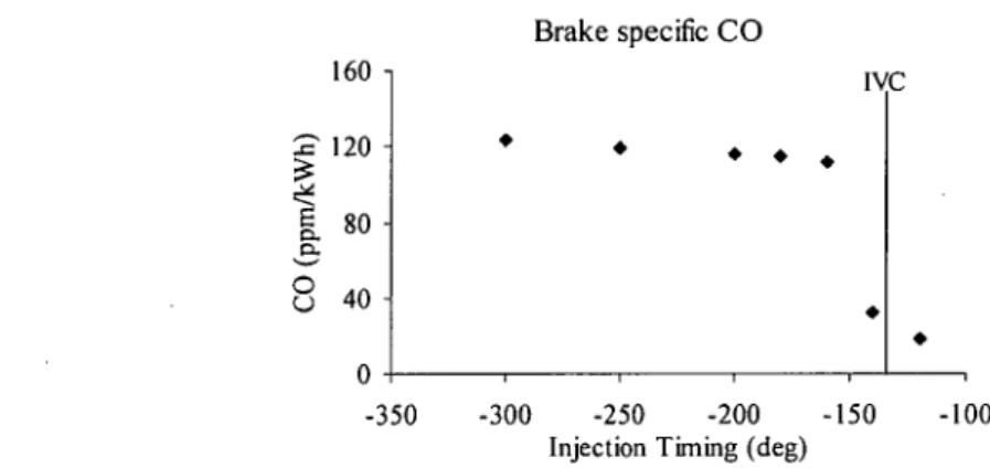
Figure 4-8 Brake specific CO emission of CNG-DI engine for various injection timing
50
Figure 4-9 Injection window for various injection pressures 51 Figure 4-10 Volumetric efficiency for various injection pressures 52 Figure 4-11 Pressure profile for injection pressure variation 53
Figure 5-1 Schematic of engine test-bed 54
Figure 5-2 Injector and Spark position 55
Figure 5-3 Homogeneous piston head shape 56
Figure 5-4 CNG fueling system 56
Figure 5-5 Quartz piezoelectric pressure transducers, (a) Courtesy of Kistler
Instrument Corp. (b) Courtesy of AVL Corp 57
x i v
Figure 5-6 Pressure as a function of volume in the engine cylinder 58
Figure 5-7 GASMET™ stationary FTIR analyzer 59
Figure 5-8 (a, b) Injection sequence at atmospheric condition for both injector spray
angle 61
Figure 5-9 Injector image 62
Figure 5-10 Typical pressure measurement system 64
Figure 5-11 Results ofheat release analysis showing the effect of heat transfer,
crevices, and combustion inefficiency 67
Figure 5-12 Calibration spectrum on FTIR system for emission analysis 72 Figure 6-1 Injection duration for different injection timing 73 Figure 6-2 Engine Performance characteristics for different injection timing 74 Figure 6-3 Volumetric efficiency for different injection timing 76 Figure 6-4 Engine performance mapping sensitivity to the injection timing parameters
78
Figure 6-5 Emission characteristics for different injection timing 80 Figure 6-6 Pressure reading characteristics for different injection timing at 3000 RPM.
82
Figure 6-7 IMEP characteristics for different injection timing 83 Figure 6-8 Cycle by cycle variation for different injection timing 84 Figure 6-9 Combustion efficiency for different injection timing 85 Figure 6-10 Heat release characteristics for different injection timing at 3000 RPM 86 Figure 6-11 Heat release rate for various injection timing 87 Figure 6-12 Pressure characteristics for different injection timing at 5000 RPM 88 Figure 6-13 Heat release rate for different injection timing at 5000 RPM 88 Figure 6-14 Mass fraction burned for different injection timing at 5000 RPM 89 Figure 6-15 Engine performance comparison between experimental and simulation
results 9Q
Figure 6-16 Nitric oxide emission comparison 90
Figure 6-17 Injection duration for different injection pressure 92 Figure 6-18 Performance characteristics for different injection pressure 94 Figure 6-19 Engine performance mapping sensitivity to the Injection pressure
parameters 96
Figure 6-20 Volumetric efficiency sensitivity for different injection pressure 97
Figure 6-21 Emission characteristics for different injection pressure 98
Figure 6-22 Emission characteristics for different injection pressure at various RPM 100
Figure 6-23 Pressure reading for different injection pressure at 3000 RPM 101 Figure 6-24 Heat release rate for different injection pressure at 3000 RPM 102 Figure 6-25 Mass fraction burned for different injection pressure at 3000 RPM 102 Figure 6-26 IMEP characteristics for different injection pressure 103 Figure 6-27 COV values for different injection pressure at various engine speed... 104 Figure 6-28 Ignition delay for different injection pressure at 3000 RPM 104 Figure 6-29 Combustion stages for different injection pressure at 3000 RPM 105 Figure 6-30 Combustion efficiency for different injection pressure at 3000 RPM .. 106 Figure 6-31 Pressure reading for different injection pressure at 5000 RPM 106 Figure 6-32 Heat release rate for different injection pressure at 5000 RPM 107 Figure 6-33 Mass fraction burned for different injection pressure at 5000 RPM 107 Figure 6-34 Ignition delay for different injection pressure at 5000 RPM 108 Figure 6-35 Combustion duration for different injection pressure at 5000 RPM 108 Figure 6-36 Combustion efficiency characteristics for different injection pressure at
5000 RPM 109
Figure 6-37 (a, b,c) Engine performance comparison 110
Figure 6-38 NOx emission comparison 111
Figure 6-39 Performance at 300°BTDC Injection timing for different Spray angle
injectors 113
Figure 6-40 Volumetric efficiency for different injector at 300 injection timing 114 Figure 6-41 Performance at 140°BTDC injection timing for different Spray angle
injectors 1L5
Figure 6-42 Volumetric efficiency for different injector at 140 injection timing 116
Figure 6-43 Emission at 300°BTDC injection timing for different injectors 117Figure 6-44 Emission at 140 °BTDC injection timing for different injectors 118 Figure 6-45 Pressure-Crank angle diagram at 3000 RPM with 140 °BTDC injection
timing 119
Figure 6-46 Heat release rate diagram at 3000 RPM with 140 °BTDC injection
timing 119
Figure 6-47 Mass fraction burned for different injector spray angle at 3000 RPM.. 120 Figure 6-48 Pressure-Crank angle diagram at 5000 RPM with 300 injection timing 121
x v 1
Figure 6-49 Heat release rate diagram at 5000 RPM with 300 injection timing 121 Figure 6-50 Mass fraction burned for different injector spray angle at 5000 RPM with
300 injection timing 122
ABBREVIATIONS
ABDC AFR ATDC BMEP BSFC BTDC CNG CO COV DI EGR FMEP HC IANGV IMEP MBT NAI
NOx RCM UHC VVT WAI WOT
After Bottom Dead Center Air Fuel Ratio
After Top Dead Center
Brake Mean Effective Pressure
Brake Specific Fuel Consumption Before Top Dead Center
Compressed Natural Gas
Carbon Monoxide Coefficient of variation Direct Injection
Exhaust Gas Recirculation
Friction mean effective pressure Hydrocarbon
International Association for Natural Gas Vehicle Indicated Mean Effective Pressure
Maximum Brake Torque Narrow Angle Injector
Nitric Oxide
Rapid Compression Machine Unburned Hydrocarbon Variable Valve Timing Wide Angle Injector Wide Open Throttle
XVUl
Chapter I: Introduction
CHAPTER I INTRODUCTION
1.1 Background
The rapid development of automotives industry is mostly driven by increasing concern of energy security and environmental problems. Hydrocarbon fuels have become the main energy source for over centuries and creating high dependencies on using hydrocarbon as fuels in every aspect in life. Hydrocarbons as a non-renewable energy source have a limited supply that eventually will be depleted especially for gasoline and diesel that have been used on the transportation sector for decades. It has forced the automotive industry to find an alternative fuel to reduce the dependencies on gasoline and diesel as fuel.
Energy
Greenhouse Gases CO-,
Exhaust Emissions CO.NOx.HC.PM
1990 1995 2000 2005 2010 2015 2020 2025
Figure 1-1 The evolution of environmental thinking[l]
Furthermore, environmental problems caused by the rapid development of automotive industry have become the concern for the future generation as seen in Figure 1-1 other than energy security. Automotive sector has contributed a large amount of air pollution and it has deteriorated the environment. In particular, air pollution such as CO and NOx can bring hazard to humans. Therefore, the environmental regulator has created strict regulations that limit the exhaust emission allowed from vehicle to ensure the environment condition and reduce harmful gasses that are dangerous to humans. Natural gas that has methane as the main composition is the cleanest fuel
Chapter I: Introduction
Exhaustible Energy Petroleum, Natural
Gas, Coal
'
Nuclear Fuel
Renewable Energy Solar Irradiation,
Water Power, Wind Energy
I
Electricity
Biomass
Water electrolysis
Diesel Petrol Ethanol Methane
F.A.M.E Methanol
More Emission
Propane- Butane
Emission
Hydrogen
Less Emission
Battery Power
Figure 1-2 Energy option for vehicle[l]
The Europe Commission has discussed the direction of alternative fuel for the next decade mainly to overcome the problems stated earlier. The Commission proposed by 2020 the use of 10% natural gas, 8% biofuels, and 5% hydrogen for transportation, while the rest of the percentages is using the conventional fuel (gasoline and diesel).
This perspective gives the picture that the natural gas development as fuel source for the next decade will rapidly increase especially in transportation sectors[l] because of natural gas potential that can gives significant contribution to both energy security and emissions problems.
The conversion to natural gas as vehicle fuel had been steadily increasing in many countries. Statistical data provided by IANGV (International Association for Natural
Gas Vehicle) shows that Malaysia is in the 20l position among all the countries that
has been using natural gas vehicle in the transportation sector after Argentina, Brazil, and Pakistan as the biggest three of natural gas vehicle fleet. (See Table 1-1)
In order to solve the energy security and environmental problems, automotive industry also has come out with systems that reduce emission and also fuel consumption. Technological developments such as direct injection (DI), variable valve timing (VVT), exhaust gas recirculation (EGR) and on-board diagnosis system (OBD) are proven to exhibit the ability to reduce fuel consumption and the emission levels to a very low limit.
Chapter I: Introduction
* *
Table 1-1 Natural gas vehicle statistics[2]
Position Country Vehicles* Refuelling
Stations VRA** Last Updated
1 Argentina 1,459,236 1,400 32 5-Dec-06
2 Brazil 1,357,239 1410 7-Mar-06
3 Pakistan 1,300,000 1230 7-Apr-06
4 Italy 410,000 558 6-Dec-06
5 India 334,658 321 Apr 06
20 Malaysia 19,000 46 1 6-Dec-06
TOTALS 6,080,582 10,068 9,176
Includes both OEM and converted NGVs
VRA = Number of Vehicle Re-fuelling Appliances
The natural gas products consist of CNG (compressed natural gas), LNG (liquefied natural gas) and LPG (liquid petroleum gas). Research has been done to compare the application of natural gas product in the internal combustion engine. LPG has higher thermal efficiency and lower fuel consumption although it has an issue with safety and high demand for household sector. CNG shows better starting and smooth acceleration but higher safety issues due to its specific gravity which is lower than air [3].
In today's application, CNG fuel was mainly applied in combination with other fuels in the bi-fuel or tri-fuel vehicle system. The fact that all fuel has different properties gives compensation to the engine setting which has to be adjusted to facilitate both fuel and create un-optimized setting for each fuel. Dedicated CNG engine is expected to utilize the advantages of using CNG as fuel which has high octane number to be applied with higher compression ratio and increase the engine efficiency. Moreover, Natural gas as an alternative fuel has potential to emit low exhaust emissions because of simplicity of the chemical bonding and has low H/C ratio.
Currently most CNG fuelled vehicles employed conventional engine technology for fueling system that use mixer to create air and fuel mixture and the engine performance for these systems is lower compared to gasoline engine. In order to improve the engine performance, the automotive company has employed fueling
Chapter I: Introduction
systems with multi port injection[4]. The new systems are claimed to perform better compared to mixer systems. Further development of CNG engine technology has focused on increasing the engine power that can be achieved by applying current SI engine technology to the CNG fuelled vehicle[4-6].
With the recent engine technological development, CNG engine has reach the direct injection stage in its application. In the implementation of EGR on CNG engine resulting as the NOx and HC emission were very low especially with stoichiometric condition. However, EGR decreased the brake efficiency of the engine[7]. While CNG engine with turbocharger is beneficial at increasing power due to higher intake charge, the power increased is still lower at low engine speed[8]. Direct injection (DI) systems in CNG engine is another way to increase the volumetric efficiency. DI system could also enhance the mixing process forming turbulence inside the combustion chamber, due to high speed delivery
1.2 Problem Statement
The implementation of mixer and port injection system to the natural gas engine gives lower torque and power output compare to gasoline direct injection because of low volumetric efficiency of the gaseous fuel. CNG as an engine fuel has slow flame speed so that advancing ignition timing is needed to get a complete combustion.
However, advance ignition timing would result in longer time fuel heat to be transferred to the wall and thus decreasing the engine efficiency. In addition, slow flame propagation of CNG is equals to longer combustion duration. Longer combustion duration could cause some portion of fuel left unburned during the exhaust stroke, and high hydrocarbon emission will be detected in the emission.
Moreover, unburned fuel is indicating combustion efficiency of an engine, so that the combustion efficiency of CNG engine is lower compare to gasoline fuelled engine. As an outcome, the employment of CNG as an alternative fuels has been resulted 13-30%
lower engine performance due to lower volumetric efficiency, combustion efficiency and longer combustion duration.
Chapter I: Introduction
1.3 Objectives
The objectives of this research are:
1. To investigate the combustion characteristics of CNG using a direct injection system on a spark ignition engine
2. To obtained a higher power output of the CNG direct-injection engine by optimizing Injection Parameters.
1.4 Scope of Works
This research is basically focused on injection parameters on CNG direct injection spark ignition engine. The injection parameters are injection timing, injection pressure and injector spray angle on the range of engine speed from 2000 RPM to 5000 RPM.
Moreover, this research was carried out in the full load wide open throttle condition on which ignition timing was set to get the maximum brake torque for each injection parameters.
1.5 Theses Organization
This thesis consists of seven chapters which are introduction, literature review, theoretical background, simulation, methodology, results and discussion, and conclusion. A whole range of systematic experimental works had been performed to meet the objective describe in chapter 1 of this thesis.
Chapter 1 describes the background of this research that also covered the current development of engine technology mainly for spark ignition engine. Further, chapter 1 consist of explanation of both advantages and disadvantages in this engine development technology. In addition, the objective and scope of works for this
research is also oulined
Chapter 2 describe the past work that had been done on this research area and the position of this research in the current area. Mainly, it explains the fueling system
Chapter I: Introduction
technology of spark ignition engine using CNG as fuel and its development along with the characteristics of each technology.
Chapter 3 presents the theoretical background for this research which will be used as the basic for simulation and analysis stage. Chapter 3 elaborates the theory on engine performance along with its efficiency and combustion characteristics that occurs inside the combustion chamber. Further, this chapter briefly explains about emission resulting from the combustion process.
Chapter 4 discussed on the simulation process including the assumption being used, parameters of input and the model building process. It also explains the simulation results that will be used as the tools to set up the experimental investigation and help to explain the experimental results analysis.
Chapter 5 specifies the equipment that had been used in this research together with its measurement capabilities and characteristics. The data gathering process is also included in this chapter together with the constraint for each parameters being researched, as well as the equation used to analyze the data that had been gathered.
Chapter 6 illustrates the experimental results on engine performance such as torque, power, fuel consumption and engine efficiency. Furthermore, detailed analysis on the combustion process that occur in the combustion chamber and emission resulted during this process is carried out for every parameters in the certain range of engine speed.
Chapter 7 contains the concluding remarks of this research and proposed work for the future development.
Chapter II: Literature Review
CHAPTER II LITERATURE REVIEW
This chapter will elaborate the development in internal combustion engine as well as the fueling systems technology. The information on CNG application in engine with the advantageous and the disadvantageous of this fuel will also be explained with the combustion strategy that has been employed to get better results derived from the engine.
2.1 Internal Combustion Engine development
Engines have been used as tools to generate power for centuries. In the early 1769, steam engine was used and became the platform for the next chapter of engine
development. Throughout the 18th and 19th centuries, people started to search for
alternative systems due to the expensive and complex systems of the steam engines.
The internal combustion engine was a promising alternative system. Over the years, there were numerous proposals on patents for internal combustion engines. Otto and Langen introduced the first concept of internal combustion engine in 1866. It was assembled as a long vertical cylinder with piston and piston rod and it had a very low power-weight ratio. This first generation of internal combustion engine was called the Otto engine and it used gasoline as fuel source. Rudolph Diesel founded an alternative system to Otto engine in 1892, which is known as the diesel engine as shown in Figure 2-1. Diesel engine required higher compression ratio to achieve the auto ignition. Typically the compression ratio is above 19:1, while for Otto engine typical compression ratio is about 10:1 and it is limited by the knock limit. As the result, diesel engine has higher efficiency and lower fuel consumption compared to Otto engine.
Chapter II: Literature Review
Figure 2-1 Diesel engine built by MAN AG
Source: www.wikipedia.com
The widespread utilizations of Otto and Diesel engine along the years had brought up energy and environment issues such as fuel depletion and environmental pollution.
These issues have resulted in increased technological development of internal combustion engines. Continues improvement was done to increase the engine efficiency and to reduce emissions. The use of alternative fuels were considered to overcome some of these issues. Technology improvement includes variable valve timing (VVT), direct injection (DI), variable compression ratio, and on board diagnosis. The use of alternative fuel such as CNG, LNG, alcohol bond hydrocarbon, and hydrogen was considered to solve not only the emission issues, but also the fuel depletion issues[l].
Technology improvement and alternative fuel were affecting emission level of an engine in many ways. Through these developments, spark ignition engine performance and emission results are getting better each day with NOx is 80% lesser than compression ignition engine. However, the green house gas (C02) emission of SI engine is higher compared to compression ignition (CI) engine[9].
Chapter II: Literature Review
2.2 CNG as an alternative fuel
The automotive industry is seen in the natural gas as a promising fuel to reduce the dependency on crude oil supply, as natural gas is expected to be available for a longer term compared to crude oil. The number of vehicle which is converted from diesel or gasoline to natural gas is increasing, and dedicated CNG-fueled vehicle shows significant increase in some countriesfl]. The use of natural gas as engine fuel actually started way back in 1974 and 1979 where gas engine was used due to the shortage of gasoline and diesel fuels. Another factor that contributed to the development of the CNG engines is the tightening emission regulations in many developed countries to the allowable emission level of the conventional engine.
Increasing environmental concern boosts the CNG engines development because of the fact that the use of CNG resulted in a lower emission. Exhaust emission gases from engines such as NOx, CO, HC, CO2, and particulate matter have polluted the air.
Release of the exhaust gas emissions into the atmosphere has contributed to smog pollution and the increase in the levels of dangerous ground level ozone.
Natural gas is primarily composed of methane and has a high H/C ratio. This makes CNG favorable fuel to reduce CO2 and CO emission[9-ll]. Although hydrocarbon emissions of CNG are lower than conventional SI engine using port injection, the HC emission in form of methane shows contradictory results as it is higher compared to gasoline-fueled engine. Some experimental works have found that NOx emission of CNG engine was higher than conventional SI engine[12-14]. Table 2-1 shows the emission standard that is applied for CNG engine.
Table 2-1 Emission standard for CNG engine[15]
NMHC THC CO NOx PM
[g/kWh]
EURO I - 1.1 4.5 8 0.36
EURO II - 1.1 4 7 0.15
The use of CNG from the point of view of engine efficiency has some advantages and the disadvantages. Advantages of CNG include, firstly, CNG possesses high
Chapter II: Literature Review
octane number (RON130) that could be applied to a higher compression ratio and
increase the engine thermal efficiency. And secondly, the flammability limits of CNG fuel are wider than gasoline, so it can operate on a very lean limit[16, 17]. As for the
results of wider flammability limits, CNG can be operated at a lower fuel consumption than that of gasoline.Disadvantages of CNG as fuel are that, firstly, power produced from CNG engine shows approximate 10% lower output compared to gasoline fuel[ 18-23]. This is due to gaseous state of CNG that decrease the engine volumetric efficiency[24, 25].
Secondly, energy content of CNG is lower, and has longer combustion duration[26].
And thirdly, natural gas engine conversion from gasoline fueled engine requires some modification on the fueling systems, valve train and ignition system[19]; However, other systems in CNG fueled engine basically operate on the same fundamental concept as that of gasoline fueled engine. Table 2-2 summarizes the conversion effect of spark ignition engine from gasoline -fueled to CNG-fueled vehicle.
Table 2-2 Conversion effect of Gasoline to CNG in Spark ignition engine[3]
Changes - Conversion from Gasoline to
CNG
Effect Scale
Change in fuel Loss of power 8% to 15%
Lower energy density of fuel Loss ofrange 40% or more
Increase in fuel storage volume Loss of available space signifcant Increase in storage weight Loss of acceleration noticeable
Improvements due to methane fuelling Improved emissions signifcant
Fuel costs Saving on fuel costs 30% or more
Savings in engine maintenance Cleaner oil and longer life noticeable
2.3 The Development of Natural Gas engine
CNG was first used as fuel for vehicles since 1920 to provide power for heavy commercial vehicle with spark ignition engine. And its rapid development happened during oil shocks in 1974 and 1979[27], CNG seems to be the best alternatives those days because of its availability and affordable price. However the use of CNG engine was slowly terminated in 1953 as sufficient amount of gasoline became available and heavy truck with spark ignition engine fell out of favor. In the year after, the use of
10
GO
£ o
^_' e _ Z£ —
< O
s 3c; O m ^ S t-
go -<i- bCO
go ac
c >
2:
Chapter II: Literature Review
CNG as fuel was slowly phased out by the use of gasoline and diesel in vehicle as
these fuels were readily available. Recently the demands on CNG engine are steadily
increasing as the world is facing the depletion of fuel source and increased concern onenvironmental condition. Further more, CNG development was pushed up by the strengthening emission regulation and with the full support from the government
institutions.
By the end of the 20th century, many automotive industries and government
institutions were giving their full attention concerning CNG engine development.
These changes are mostly driven by stricter emission regulations that emphasize these institutions to find the best alternatives fuel. Current problem faced by conventional
diesel and gasoline engine is the emissions emitted consist of CO2, NOx, CO and hydrocarbon. These emissions give detrimental effect to the environment as it can bring green house effect and some are harmful to humans.As an alternative, CNG fuelled engine are developed to meet the power and efficiency of the available engines which are gasoline and diesel engine[25, 27, 28], with significantly lower harmful emission.
Among the innovations that the engineers and researchers have come up with regards to CNG engine are:
i. Engine format:
Dedicated / Monofuel with higher compression ratio with supercharger or turbocharger, bi-fuel / dual fuel, tri-fuel engine
ii. Fuel delivery systems:
Carburetor, Single port injection, Multi port injection, and Direct injection
iii. Combustion strategy:
Stoichiometric and Lean burned combustion
Chapter II: Literature Review
2.3.1 Engine Format:
i. Dedicated/Monofuel engine is a dedicated engine that uses only natural gas as its fuel source. A dedicated engine has the advantage of being optimized to operate on natural gas. Thus it ensures maximum efficiency and minimum emission results. As the vehicle has been optimized for natural gas engine, the distance it can travel depends on the CNG volume carried by the vehicle
ii. Bi-fuel/dualfuel is the engine which operates on either natural gas or gasoline.
Bi-fuel engine generally relies on gasoline to start the engine, thus a small portion of gasoline is still required to get a good cycle. These engines are usually optimized to run on one fuel. The deficiency in running CNG fuel are compensated by the use of a supercharger or turbocharger.
iii. A relatively recent technology, a tri-fuel engine combines a flex-fuel (flexible fuel) vehicle and natural gas engine vehicle. A flex fuel vehicle uses gasoline and ethanol, either exclusively or blended together. Tri-fuel vehicles first entered the market in 2005 in Brazil, where ethanol and NG were widely used as a transport fuel[29].
2.3.2 Fuel delivery system:
Fuel delivery system has been investigated along with other technology development and it has been developed over the years, from conventional Carburetor system to a sophisticated Direct-injection system. The purpose of the development is to ensure the precise amount of fuel supply that is required for combustion process. Along with precise control of fuel, mixing control of fuel and air is important parameters that are affected by fuel delivery methods. Controllable mixing can ensure the good and stable combustion takes place in the combustion chamber.
i. Carburetor
Carburetor is among the first fueling system that comes along with engine technology. It delivers fuel with a less complicated system and it has less control to the amount of fuel that enters the system as shown in Figure 2-2.
More complicated carburetor has been introduced to control fuel delivery in
12
Chapter II: Literature Review
such way. However, due to its nature, carburetor system has its limitation to control fuel to a very specific amount.
The basic principal of carburetor is differential pressure that occurs during intake process inside the intake manifold and throttle. High velocity of air entering intake manifold will pass the throttle and reduce the pressure in the
throttle, while the reduction in diameter from intake to throttle will create vacuum condition. Pressure difference between fuel rail and throttle will pull out some amount of fuel and instantly mix with air. A homogeneous mixture
will be created and enter the combustion chamber.
AIR Basic Carburetor (Crou Svctlon)
Figure 2-2 Carburetor
CNG fueled engine with carburetor system had 13-30% drop in engine performance compared to gasoline engine, and 13-17% performance drop if it used more complex system with additional AFR controller. As expected from CNG, the exhaust emission emitted from CNG engine was 90% and 50%
lower for CO and HC emissions respectively compared to gasoline engine[20, 30].
ii. Single point injection / Throttle bodyfuel injection.
The improvement had been done to improve the control on fuel delivery with Single point injection (SPI), which was basically a replacement for carburetor systems. SPI was an incorporated electronically. It controlled fuel injector valves into the throttle body and was designed as a bolt-in replacement for carburetor, so the automakers did not have to make any drastic changes to their engine design.
Figure 2-3 shows the main component of SPI systems. The SPI system consists of fuel pump, fuel filter and carburetor unit. Power to the system is
Chapter II: Literature Review
supplied by the power relay, which has built-in timer and allows throttle valves to continue to operate after the engine is switched off. SPI basically is a carburetor derivative. However, instead of having the induction vacuum sucking the fuel into venture, an injector forced fuel into the air flow. This system allows more precise control on fuel delivery by injecting the amount of fuel required by the combustion process. Furthermore, it can decrease the fuel consumption of an engine. CNG application on SPI system can increase the engine performance compared to carburetor system due to its precise control in regulating air-fuel ratio[30].
«^.«p
1 Fuel injector assembly
2 Fuel pressure regulator components 3 Fuel inlet connector
4 Air charge temperature (ACT) sensor 5 Throttle valve control motor 6 Throttle position sensor (TPS) 7 Fuel injector wiring
Figure 2-3 Single point injections
Source: Ford 1.4 CFI engine maintenance manual
SPI system of CNG had 14.4% lower IMEP output at 4500 RPM and 13.8%
lower at rated speed in comparison with gasoline fuel because CNG fuel has small effect on cooling the intake charge as gasoline does. As the results, inlet temperature for CNG will be higher and reduces the volumetric efficiency of the engine[31].
//'/'. Multi Port Injection (MPI)
As the engine design advanced, single point injection (SPI) was phased out and replaced by multi-port fuel injection (MPI). This design placed single
14
Chapter II: Literature Review
injector for each cylinder and the injector is normally attached either on the intake manifold (employed by 80% of MPI system) as seen on Figure 2-4 or on the cylinder head upstream (20% of MPI system employed), and both aimed right at the intake valve. Mostly, MPI system in gasoline engine inject
the fuel when the intake valve is closed so that there will be an associated time
lag between the injection event and fuel/air mixture induction into the combustion chamber. During this time lag, fuel and air will be mixed and create homogeneous mixture before entering the combustion chamber[32].
While, MPI systems of CNG engines inject the fuel when the intake valve is open, which eliminates the time lag factor[4, 33].
Exhaust Valve
Injector
Figure 2-4 Multi port injection (MPI) [34]
The MPI system consists of three major parts, which are injectors, fuel pump and ECU. ECU is mainly used to control the injection event parameters such as injection timing and fuel required by each cylinder, such that by employing ECU, MPI systems use more sophisticated system compared to SPI system[2, 35]. However, MPI system utilization can accurately deliver the fuel requirement for each cylinder as such that the fuel metering will be enhanced and fuel consumption will be decreased. Moreover, MPI usage somehow increases the control on combustion process which improve the engine performance[33]. Along with increasing engine performance, the emissions emitted were also decreasing especially for CO and HC emission compared to carburetor system as shown in Table 2-3.
Chapter II: Literature Review
On the perspective of CNG fueled engine, MPI systems had 9.95% and 10.4%
lower IMEP values for 4500 RPM and rated RPM respectively compared to MPI-gasoline. Further, it also has 3% to 5% better performance if compared to SPI-CNG system[31].
Table 2-3 Tailp ipe emission (un-catalyzed) anc fuel composition[36]
Vehicle Tailpipe emissions-measured Fuel consumption-measured
Model Fuel system HC (g/km)
CO (g/km)
Nox (g/km)
HC+NOx (g/km)
(g/km)
(1/100 km) (km/I) Absolute Relative
Large 2S'(150- 200 cm3 2-stroke)
Large 4S'(I50- 200 cm3 4-stroke)
Carburetor (baseline) aSDI' (Euro I system) Carburetor (baseline) SePI' (Devel system)
8.5
1.06 1.76
0.85
0.5
10.9
1.47 1.82
11.1
1.34
0.04
0.09 0.06
0.17
0.25 8.5
1.16 1.82
1.02
0.72
33.4
19.6 20.4
246
20.5
-41%
-39%
-17%
4.43
2.58 2.7
3.33
2.79
22.6
38.7 37
30
35.9
iv. Direct Injection (DI) System
The most recent technology development on fuel delivery system is direct injection. Over the past three decades, a research goal has been to develop an internal combustion engine that combines the best feature from spark ignition and compression ignition engines. Such an engine would exhibit a brake specific fuel consumption approaching that of a diesel engine, while maintaining the operating characteristics and specific power output of gasoline engine. Direct injection-four stroke-spark ignition engine believes to be the answers to this objective because it does not throttle the inlet mixture to control the load. In direct injection system (Figure 2-5), the fuel is directly injected to the combustion chamber instead of separate chamber or port and the load is controlled by varying the amount of fuel that is injected to the cylinder.
16
Chapter II: Literature Review
Figure 2-5 Direct injection systems
Source: http://www.emercedesbenz.com/
Typical spark ignition direct injection (SI-DI) engine consists of high pressure fuel pump, injector and ECU, where the ECU function is to control the amount of fuel injected and injection timing.
Direct injection system has several advantages compared to MPI system.
These advantages are higher fuel economy, drive-ability, AFR controllability, combustion stability, better emission and increasing engine efficiency by 10- 20%. However, DI has some limitation with a very complex control system, low injector performance and durability and higher amount of local NOx[37].
In the CNG fueled engine, direct injection system offers a better control on AFR [12] which affects the exhaust emission of CNG engine. In addition, it can provide very low allowable lean limit down to 0.1 equivalence ratio, which indicates a very low fuel consumption[38]. Further, DI employment on CNG engine could reduce the cycle-by-cycle variation from 23.7% to 4% and 1.6% respectively for late and early injection mode with AFR equals to 23[39]. DI also offers faster combustion rate because of its capability to generate turbulence[40]. However, a drawback of DI-CNG engine is emitting high level of NOx emission due to higher combustion temperature resulting from increased combustion process.
Other research that compared the direct injection method with mixer system and the results state that the maximum brake power for DI systems is 7.7%
higher than that mixer engine, while the thermal efficiency of DI is increased up to 98.8% which resulted in decrease of NOx emissions[41].
Chapter II: Literature Review
2.3.3 Combustion strategy
Currently there are two types of combustion strategy that has been utilized on CNG- DI engine, stoichiometric and lean-burned combustion. Both systems are based on the specific amount of fuel injected to the system.
i. Stoichiometric Combustion
Stoichiometric or theoretical combustion is the ideal combustion process during which a fuel is burned completely and it depends on the fuel composition. CNG which primarily composed of methane had a stoichiometric air-fuel ratio around 16.9. Stoichiometric systems offer exceptionally clean combustion especially with the employment of EGR and three-way catalyst, where it can reduce more than 90% NOx and methane emission[12]. On the other hand, stoichiometric system on CNG engine performance was down to 20%> for BSFC and 15% for BMEP compared to gasoline fueled engine[14, 42]. Furthermore, CNG stoichiometric has slower burning rate and longer ignition delay compared to gasoline engine.[43]
Stoichiometric combustion has been used in light duty applications because it can be equipped by three-way catalyst and after treatment technology to meet light duty emission standard. The stoichiometric natural gas engine performs remarkably low emission results thanks to high catalyst efficiency compared to lean-burn combustion. However, the emission results are highly dependant on the stability of air-fuel ratio of the engine. As changes in AFR values could affect the emission results[44].
In addition, the engine performance could be improved and exhibit high tolerant on gas property variations with, the use of feedback control which is using an oxygen sensor to control air-fuel ratio. As an effect, high thermal efficiency of stoichiometric engine come at a price of higher combustion temperature and reduced fuel economy[2].
ii. Lean-burned Combustion
Lean-burned combustion is the combustion process during which a fuei is burned in the ratio that provides excess air. Lean burn combustion offers low fuel consumption with capability to operate under a very lean limit, where the
Chapter II: Literature Review
lowest lean limit of CNG is approaching 0.02 equivalence ratio way below the limit of gasoline direct injection engine. With 0.3[45] equivalence ratio, the engine performance of lean burn combustion shows at least twice the power produced by stoichiometric combustion but with the consequences of much higher NOx and HC emission emitted from lean burn combustion method[46].
Compared to stoichiometric combustion, lean burn combustion shows higher values for coefficient of variation due to variation of mixture properties in each engine cycle. Controlling mixture formation is the main concern for researchers to get the stable engine operation using lean burn combustion system [47].
The application of lean burn engine is in the range of medium to heavy duty application, in which low fuel consumption and reducing emission without after treatment technology are the main concern of its development[2].
2.4 Compressed Natural Gas Direct Injection (CNG-DI) Engine
Emission reduction is one of a key task for automotive industries. Therefore, energy resources offering advantage with respects to emission savings are of high interest.
CNG offers this benefit by emitting lower emission compared to liquid fuel due to its chemical properties. Additionally, CNG has potential to increase thermal efficiency of spark ignition engine due to its combustion properties such as high knock resistance and extreme stratification capabilities for lean air-fuel ratio.
For current passenger car standard applications, a power drop of approximate 10% is noticed by the use of CNG, which occurs from reduced volumetric efficiency. But this drawback can be compensated by direct injection of CNG straight into the combustion chamber. It was noticed that direct injection system has 9-35% higher IMEP compared to MPI system from the effect of improved volumetric efficiency[39, 48].
However, emission level of CNG-DI engine is higher compared to MPI system especially for NOx and HC emission near stoichiometric condition.[49] Controlled combustion with controlling mixture preparation is hoped to solve this problem.
Furthermore, regulating injection parameters such as injection timing, injection
Chapter II: Literature Review
pressure and spray angle of injector to control the mixture preparation is hoped to solve a drawback in emission and it could increase the power resulted by the engine.
There are two types of mixture preparation method, homogeneous charge and stratified charge[32, 37, 50].
2.4.1 Stratified charge operation
Stratified charge is the mixture condition which some amount of fuel stratification exists before the combustion takes place. This condition is achieved by injecting the fuel relatively late during the cycle. Stratified charge operation was applied on idle- medium engine load and engine speed in gasoline direct injection engine in order to achieve maximum fuel economy.
An experimental study to improve direct injection parameters on natural gas engine performance has been done. As the outcome that the combustion and emission parameters are not significantly influenced by the modes of fuel injection such as the number of injectors, position of the injectors and the arrangements of injector regards to spark position. Furthermore, the pressure rise due to combustion for direct injection is higher compared to homogeneous/port injection[38].
As mentioned before, time availability for mixing is important on natural gas engine combustions. Degree of stratification of fuel inside the combustion chamber is an important parameter. Controllable charge stratification can make the combustion process better. Study on the possibility of controlling the charge stratification was done. CNG-DI stratified combustions systems can realize overall shorter combustion compared to homogeneous system. And the combustion efficiency can be maintained more than 0.92 in the range of equivalence ratio from 0.1 to 0.9[17].
The basic characteristics of CNG direct injection have been investigated. Stratified combustion strategy was investigated at rapid compression machine (RCM) that has 10 compression ratios. The result shows that compared to homogeneous system, stratified combustion has higher heat release rate for wide range of §. Furthermore, emission result shows that for CO and C02 emission, stratified charge has better
20
Chapter II: Literature Review
performance. In contrary, hydrocarbon emission of natural gas is higher in respect
with gasoline. Higher heat release rate and peak pressure lead to high NOx emission.However, the NOx emission result is the same as gasoline. The combustion duration of CNG is faster for initial combustion (0-10%) in the combustion process, but slower at main stager of combustion (10-90%). Equivalence ratio has less effect on combustion duration of CNG[51]. Injection timing has significant effect on combustion of CNG, which can be seen on the variation of heat release rate pattern and emission obtained from CNG combustion. Moreover, the possibility of CNG-DI on spark ignition engine has been researched[17]. Wide operational range of equivalence ratio and high-energy conversion efficiency are the basic thought for CNG-DI implementation on spark ignition engine. The combustion duration of CNG with stratified system is shorter than CNG-homogeneous by significantly decreasing time interval between injection timing and ignition timing. Pressure rise due to combustion is insensitive to the injection timing parameter[52].
Combustion stability of CNG-DI engine is high with less cycle-by-cycle variation at the maximum pressure rise. The of CNG-DI is approximately 2% for wide range equivalence ratio. Furthermore, the combustion stability of CNG-DI is less sensitive to equivalence ratio and the variation of NOx shows interdependence with variation of rapid combustion duration. For CO and hydrocarbon, variation of late combustion duration is related to the variation CO and HC emission[53].
2.4.2 Homogeneous charge operation
Homogeneous charge is the control strategy in which the mixture of fuel and air had achieved homogeneous mixture before the ignition event can be realize with the use of early injection timing on direct injection system. The reason of this is with the use of early injection timing, significantly longer time for mixture preparation is
available.
Homogeneous systems on gasoline direct injection offers good exhaust emission results thanks to stoichiometric after treatment systems. Combines with direct injection, homogeneous systems offers the possibility to reduce fuel consumption that
Chapter II: Literature Review
has been addressed as the disadvantage of the system compared to stratified combustion[6].
CNG direct injection homogeneous systems was investigated by Zuohua Huang .et al.
(2001). The experiment was done on rapid compression machine (RCM). It was stated that combustion efficiency of CNG direct injection operated at homogeneous charge is higher than that of stratified systems at stoichiometric condition. While at lean operation, stratified charge stratification has higher combustion efficiency[17].
CNG direct injection engine operated at homogeneous charge had lower methane emission, but it had higher nitric oxide emission than that of stratified charge stratification. These emission trends may be due to a higher combustion efficiency of homogeneous charge compare to stratified systems[38, 45].
There are few experiments on homogeneous charge direct injection CNG engine because of the higher fuel consumption limits compared to stratified charge[17, 45].
But the emission of homogeneous charge systems which is lower compared to stratified systems especially using catalytic converter made homogeneous systems favorable. Longer combustion duration as the disadvantage of homogeneous combustion systems is the obstacle that needs to be solved. Furthermore, the problems with methane and NOx emission on CNG engine need to be reduced. Implementation of direct injection systems at CNG engine is beneficial for combustion enhancement process. Momentum generated by CNG injection is 3 times higher than gasoline.
Higher turbulence intensity is achievable. The pressure difference between injection pressure and ambient pressure are determining parameters for momentum generation inside the combustion chamber. The higher the pressure difference the greater is the momentum generated by injection is [26]. It was observed that the concentration of NOx drops to a very low level at stoichiometric air/fuel ratio. It leads to NOx emissions on CNG-DI engine can be reduced by increase the equivalence ratio (<j>).
Homogeneous charge operating method is designed to meet the requirement of medium-high engine loads. In order to facilitate these needs, the power output of a CNG direct injection engine has to be increased by increasing the turbulence level
22
Chapter II: Literature Review
inside the combustion chamber since turbulence is needed to enhance the combustion
speed of CNG homogeneous mixture especially to improve the mixing process mainly at low engine speed[54]
From the literature review, it can be conclude that the possibility of direct injection systems to be applied on CNG engine could increase the performance of the engine.
In order to get more power on the engine, one has to optimize the parameter that controls the injection events in direct injection systems. Injection parameters such as injection timing[41, 49, 52, 53, 55-58], injection pressure [32, 37, 41, 50, 59]and type of injectors[32, 59, 60] had proven to be important parameters that affect the combustion and performance of direct injection engine. Therefore, the research will be focused on optimizing the injection parameters in order to improve the power output of CNG direct injection engines.
Chapter III: Theoretical Background
CHAPTER III
THEORETICAL BACKGROUND
3.1 Thermodynamics principles
This chapter provides criteria by which to estimate the performance of internal combustion engines. Most important are thermodynamics cycles based on ideal gas undergoing ideal process. However, internal combustion engine follows mechanical cycle. The start and end points are mechanically similar in the cycle for internal combustion engine, whether it is two-stroke or four-stroke mechanical cycle.
It is very convenient to compare internal combustion engine with ideal air standard
cycle as a simple basis for comparison. Air standard cycles have limitations as air and
fuel mixtures do not behave as an ideal gas. Despite this, the simple air standard cycles are very useful, as they indicate trend.Commonly, there are 3 types of air standard cycles which are used to represent internal combustion system. These are the ideal air standard Otto cycle for spark
ignition engine, the ideal air standard Diesel cycle for compression ignition engine,
and air standard dual cycles that combine Otto and Diesel cycle. In this chapter weonly discussed the ideal air standard Otto cycle as representative of the experimental
engine.
3.1.1 The ideal air standard Otto cycle.
The Otto cycle is usually used as basis for spark ignition engine and high-speed compression ignition engines. The cycle consists of four non-flow processes. The compression and expansion process are assumed to be reversible adiabatic, and thus
isentropic.
Chapter III: Theoretical Background
The processes are as follows (Figure 3-1):
1-2 Isentropic compression of air through a volume ratio VjV2 , the compression
ratio rv2-3 Addition of heat Q2Z at constant volume 3-4 Isentropic expansion of air to the original volume
4-1 Rejection of heat Q4] at constant volume to complete the cycle
V (volume)
Figure 3-1 Pressure-Volume diagram for air standard Otto cycle.
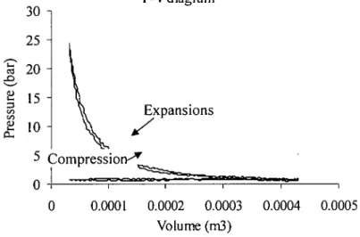
3.1.2 Mechanical cycles
Internal combustion engine operates in mechanical cycle, not a thermodynamic cycle.
Nevertheless, it is convenient to analyze engine behavior using hypothetic cycles from thermodynamic cycle. The mechanical cycle can be represented by pressure-volume diagram in Figure 3-2.
Chapter III: Theoretical Background
65 "
55 - _. 45 •
& 35 "
s?
«
2 25 -
a
15 -
-5
P-V Diagram
0.0001 0.0002 0.0003
Volume (m'J)
0.0004 0.0005
Figure 3-2 Mechanical cycles of internal combustion engine
Figure 3-
![Figure 1-2 Energy option for vehicle[l]](https://thumb-ap.123doks.com/thumbv2/azpdforg/11079496.0/20.827.156.688.75.372/figure-1-2-energy-option-for-vehicle-l.webp)