DOI: 10.12928/TELKOMNIKA.v15i2.6246 628
Peripheral Slits Microstrip Antenna Using Log Periodic
Technique for Digital Television Broadcasting
Indra Surjati*1, Yuli Kurnia Ningsih2, Syah Alam3
1,2
Graduate Programme of Electrical Engineering, Faculty of Industrial Technology Trisakti University, Jln. Kyai Tapa No.1 Grogol, Jakarta 11440
3
Electrical Engineering Departement, Faculty of Engineering 17th August University Corresponding author, e-mail: [email protected]*1, [email protected]3
Abstract
This paper proposed a new design of log periodic microstrip antenna using peripheral slits for dgital video broadcasting applications in DKI Jakarta. Applying peripheral slits can be reduced the dimension of antenna up to 62.6% with its dimension 400 mm x 150 mm using 4 patches in different frequencies. The patches are one another connected using log periodic technique. The measurement results showed that the antenna was operating at frequency ranges of 450 MHz to800 MHz with impedance bandwidth of 350 MHz, VSWR ≤ 2 and return loss ≤ -10dB. The proposed antenna could receive 11 DVB stations with high definition quality pictureand only channel number 24, such as RCTI, Global TV and MNC TV can not reveive signals as expected.
Keywords: digital video broadcasting, peripheral slits, log periodic, microstrip antenna
Copyright © 2017 Universitas Ahmad Dahlan. All rights reserved.
1. Introduction
Digital television broadcasting is a technology that can not be avoided by any country in the world. The development of digital television broadcasting technology becomes a global demand which nearly each country has and in the process towards the transition from analogue to digital broadcasting systems. The advantages of digital television broadcasting such as high definition picture quality, sound system are of sharper and better efficient allocation of radio frequencies [1].
Digital television broadcasting standard has been also developed from Digital Video Broadcasting-Terrestrial (DVB-T) to Digital Video Broadcasting - Second Generation Terrestrial (DVB-T2). The Indonesian Government has adopted the regulation on standard fixed and not paid Digital Terrestrial Television Broadcasting (free-to-air); known as DVB-T2 digital terrestrial television broadcasting free-to-air standar in Indonesiaas manifestated with the Minister of Communications and Information Technology Regulation No. 05/PER/M.KOMINFO/2/2012 [2]. Beside this regulation, the digital television system in Indonesia also follows the Regulation of Minister of Communication and Information Technology Number 23/PER/M.KOMINFO/11/2011 on the Master Plan of Radio Frequencies for Television Broadcasting in the Digital Terrestrial Radio Frequency Bands between 478 MHz-694 MHz [3].
Several studies related to the producing of digital television receiver antennas with certain expected characteristics were the use of slot technique that produced a dimension of (204.8 x 160.6) mm with omnidirectional radiation pattern and VSWR ≤ 2 [4], research already done by [5] using 5 pieces of element patch log periodic that produced dimension of (169.4 x 113.8) mm, and producing a 2 x 2 array antenna with dimension of (515 x 300) mm [6]. Another research done by [7] proposed a linear array antenna.
Peripheral slits were able to produce a compact antenna with smaller dimension. This technique could reduce microstrip patch antenna up to 33% of its original size. Therefore peripheral slits technique is one method to optimize the microstrip antenna dimension [13]. Peripheral slits is a method of miniaturization techniques microstrip antenna by using some slits on patch antenna.
Based on previous studies results it can be inferred that the peripheral slits method can reduce antenna size. Therefore this paper proposed a new design of peripheral slits microstrip antenna using log periodic technique fed by microstrip line.
2. Antenna Design
The design of the proposed antenna is made based on one layer substrate with relative permitivity ( r) of 4.3, substrate thicknes (h) of 1.6 mm and loss tangent (tan ) of 0.0265. The dimensions of the rectangular patch antenna are given by the equations as follows.
By embedding a stub at the microstrip line, the matching condition can be well achieved and the value of return loss and VSWR can be improved by adjusting the length and width of the stub. Having several iterations related those parameters, afterward peripheral slits was embedded to reduce the dimension of the patch antenna.
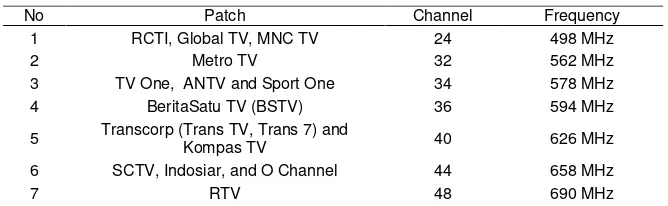
The antenna can be applied at various frequencies as presented by Table 1 for Digital Television Broadcasting application in DKI Jakarta Region.
Table 1. DVB Frequencies for DKI Jakarta Region
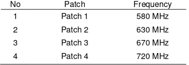
All of those frequencies in Table 1 are classified into four groups of patches as shown in Table 2. These all four patches are combined using log periodic technique which is shown in Figure 1.
Table 2. Frequency of Each Patch Antenna
No Patch Frequency
1 Patch 1 580 MHz
2 Patch 2 630 MHz
3 Patch 3 670 MHz
4 Patch 4 720 MHz
Table 3. Dimension and Size of Log Periodic Peripheral Slit Microstrip Antenna
Patch 1 W1 = 77.4 mm L1 = 89.5 mm Y1 = 27.8 mm Ls1 = 24 mm
Patch 2 W2 = 77 mm L2 = 80 mm Y2 = 28 mm Ls2 = 24 mm
Patch 3 W3= 65 mm L3 = 73 mm Y3 = 23 mm Ls3 = 14 mm
Patch 4 W4= 58 mm L4 = 65 mm Y4 = 23 mm Ls4 = 14 mm
Figure 1. Peripheral Slits Microstrip Antenna Using Log Periodic Technique
3. Results and Analysis
Return loss and VSWR value can be obtanined after having several iterations by adjusting the width and length of the patch antenna and also the dimension of the slits. To produce the best value of return loss and VSWR can be achieved by controlling the length of the microstrip line and the stub length, and the outcome of return loss and VSWR can be seen in Figure 2.
(a) (b)
The overall iteration are summarized in Table 3 for the parameters of the proposed antenna and in Table 4 for the return loss value. Its can be seen the return loss results of ≤ -10 dB in the range of 482.7 MHz to 740.5 MHz can be achieved at the third iteration by varying the parameters of the width of the second patch (W2), the length of the first patch (L1) and the length of the second patch (L2).
Table 3. Iterations of the parameters antenna
Iterations Parameters (mm)
W1 W2 W3 W4 L1 L2 L3 L4
1 77.4 70 65 58 83.5 80 73 65
2 77.4 73 65 58 83.5 73 73 65
3 77.4 77 65 58 89.5 80 73 65
Table 4. Return Loss Results
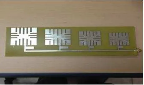
The fabrication of the proposed microstrip antenna design was done after the simulation of the third iteration process. FR4 Epoxy substrate and SMA connector which have 50 Ohm impedance value are used in this fabrication and the fabrication result can be seen in Figure 5.
Figure 5. Fabrication of microstrip antenna design
After the fabrication, the measurements of return loss and VSWR have been done in the laboratory as seen in Figure 6 and Figure 7. From Figure 6 it can be sen that the proposed antenna can work at the range frequency between 498 MHz to 690 MHz for Digital Television Broadcast application in DKI Jakarta Region.The impedance bandwidth of the measurement result is 350 MHz (450 MHz–800 MHz) compared to 257.8 MHz (482.7 MHz 740.5 MHz) from the simulation process. It can be seen that the impedance bandwidth from the proposed antenna is increased up to 35.76%.
From Figure 7, VSWR ≤ 2 from the proposed antenna can be achieved in the frequency range 470 MHz to 740 MHz.
Iteration Return Loss (dB)
C.24 C.32 C.34 C.36 C.40 C.44 C.48
1 -11.6 -25.9 -17.8 -28.5 -11.7 -9.3 -13.1
2 -6.3 -15.7 -14.6 -14.3 -21.7 -12.7 -12.7
Figure 6. Measurement of Return Loss
Figure 7. Measurement of VSWR
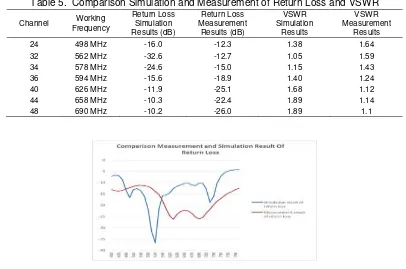
The results of return loss and VSWR of the simulation and measurement are tabulated in Table 5 and the graphic of the comparison are seen in Figure 8 and Figure 9 below. From Table 5 it can be seen that all of the return loss value is ≤ -10 dB and also the VSWR value is ≤ 2. With this results indicated that all of the channel of DVB stations can receive the signal.
Table 5. Comparison Simulation and Measurement of Return Loss and VSWR
Channel Working Frequency
Return Loss Simulation Results (dB)
Return Loss Measurement
Results (dB)
VSWR Simulation
Results
VSWR Measurement
Results
24 498 MHz -16.0 -12.3 1.38 1.64
32 562 MHz -32.6 -12.7 1.05 1.59
34 578 MHz -24.6 -15.0 1.15 1.43
36 594 MHz -15.6 -18.9 1.40 1.24
40 626 MHz -11.9 -25.1 1.68 1.12
44 658 MHz -10.3 -22.4 1.89 1.14
Figure 9. Comparison Measurement and Simulation Results of VSWR
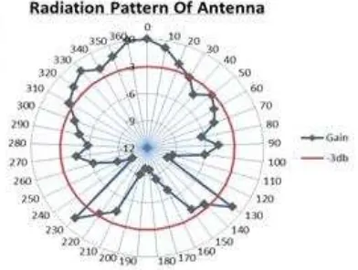
Figure 10 shown the radiation pattern from the proposed antenna design with Half Power Beamwidth (HPBW) of 1200 and its indicated that the radiation pattern is broadside.
Figure 10. Radiation pattern with HPBW 120o
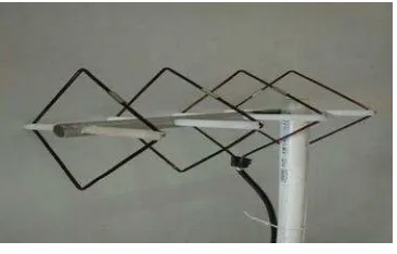
After the measuring process is finished, the antenna was applied for DVB application for DKI Jakarta and Figure 11 showed the diagram block for the inspection process of the antenna design. Yaggi antenna as seen in Figure 12 is used as comparison to analyze the perfomance of the proposed antenna design.
Figure 11. Diagram block of the inspection process
Figure 12. Antenna Yaggi model
The results which is presented by Table 6 below showed that the proposed antenna design can receive 11 DVB application stations with high definition quality picture as seen in Figure 13, as compared to Yaggi antenna that can receive 15 stations.The proposed antenna design could not received the signal only for channel 24, such as RCTI, Global TV, and MNC TV, because gain of the antenna design is 11.62 dB compare with gain of the Yaggi antenna of 13 dB.
Table 6. The Received Frequency Between Yaggi Antena and Microstrip Antenna
No TV Station Yaggi Antenna Microstrip Antenna
1. RCTI, Global TV, MNC TV Received Not Received
2. Metro TV Received Received
3. TV One, ANTV and Sport One Received Received
4. BeritaSatu TV (BSTV) Received Received
5. Transcorp (Trans TV, Trans 7)
danKompas TV Received Received
6. SCTV, Indosiar, and O-Channel Received Received
4. Conclusion
The proposed of peripheral slit microstrip antenna using log periodic technique with return loss value of ≤ -10 dB and VSWR value ≤ 2 can be achieved by adjusting the dimension of the patch antenna and the slits and also the length of the feed line and the stub length. Using peripheral slits technique the dimension of the patch antenna can be reduced up to 62.6% and can produce a compact antenna with smaller dimension. Using log periodic technique can increase the bandwidth of the antenna and the impedance bandwidth from the measurement is 350 MHz compared to 257.8 MHz from the simulation process. The proposed antenna could receive 11 DVB stations with high definition quality picture and only channel 24, such as RCTI, Global TV, and MNC TV can not reveived the signal.
Acknowledgement
The authors wish to express their gratitude to The Ministry of Research and Higher Educationn of Republik Indonesia for their support through Hibah Penelitian Unggulan Perguruan Tinggi No.777/K3K/KM/SPK.LT/2016 dated on 22th of September 2016.
References
[1] Seminar of the Ministry of Communications and Information Directorate General of Post and Informatics, Indonesia Goes Digital Communication Information, Jakarta: Administrator. 2012: 1-15. [2] Regulation No. 05 / PER / M.KOMINFO / 02/2012 on Standards for Digital Terrestrial Television
Broadcasting Revenue Fixed Not Paid (Free-To-Air). 2012: 1-3.
[3] Regulation No. 23 / PER / M.KOMINFO / 11/2011 on Master Plan (Masterplan) Radio Frequency For Purposes of Terrestrial Digital Broadcast TV On the Radio Frequency Band 478-694 MHz. 2011: 1-10. [4] A Adrian Gulfyan Putranto, Aloysius Adya Pramudita. Designing Microstrip Slot Antenna Receiver
System for Digital Television. RiTekTra, Jakarta. 2013.
[5] Sri Anggaraeni Kadiran. Log Periodic Patch Techniques to Widen Bandwidth Microstrip Antenna TV Receiver. ORBIT. 2013; 9(2).
[6] Andrew Mulia. Design and Realization Based Omnidirectional UHF Television Antenna Microstrip For Applied in Tasikmalaya Region. Telekontran. 2013; 1(2).
[7] T Isernia, A Massa, AF Morabito, P Rocca. On The Optimal Synthesis of Phase Only Reconfigurable Antenna Arrays. Proceedings of the 5th European Conference on Antennas and Propagation (EuCAP 2011). Rome, Italy. 2011: 2074-207.
[8] Hetal M Pathak et al. Design of Log Periodic Dipole Array Antenna Using Two Sides With Comparision of Two Dielectric Material Results. Journal of Information, Knowledge and Research in Electronics and Communication Engineering. 2013; 2(2).
[9] Giovani Andrea Casuladan Paolo Maxia. A Multiband Printed Log Periodic Dipole Array for Wireless Communications. International Journal of Antenna and Propagation, ume. 2014.
[10] Fang Lei et al. A Monolayer Multi Octave Bandwidth Log Periodic Microstrip Antenna. Progress In Electromagnetics Research Letters. 2013; 41: 97-104.
[11] Tauseef Tauqeer et al. Analytical Comparision of Wideband Microstrip Log Periodic and CPW Antennas. Microwave and Optical Technology Letters. 2014; 56(8).
[12] Hamed Ghanbari Forshtami et al. Wideband Log Periodic Microstrip Antenna with Elliptic Patches.
Journal of Information System and Telecommunication. 2013; 1(2).