A NEW APPROACH TO FAST MOSAIC UAV IMAGES
Qingyuan. Liu
1, Wenyang. Liu2, Lei. Zou1, Jinling. Wang2, You. Liu1 1
Department of Geomatic Engineering, Central South University, Changsha, Hunan, [email protected] 2
School of Surveying and Spatial Information Systems, University of New South Wales, Sydney, Australia- [email protected], [email protected]
Commission I, WG I/V
KEY WORDS
:
Mosaic UAV Images, Coordinate Transformations, Displacement of Images, Image Mosaic ErrorsABSTRACT:
Unmanned Aerial Vehicles (UAVs) have been widely used to acquire high quality terrain images of the areas of interest, particularly when such a task could potentially risk human life or even impossible as the areas cannot be accessed easily by surveyors. Once the images have been obtained, traditional photogrammetric processing process can be used to establish a relative orientation model and then, absolute orientation model with the procedures of space resection and intersection. In many such applications, the geo-referenced images which are stitched together to represent the geospatial relationships for the feature objects are sufficient. A fast or near real-time processing approach for UAV images using GPS/INS data has being investigated for years. One beneficial application of such approach is the capability of quick production of geo-referenced images for various engineering or business activities, such as urban and road planning, the site selection of factories and bridges, etc. In this paper, we have proposed a new fast processing approach for the UAV images collected with an integrated GPS/INS/Vision system. The approach features that the corresponding points between images have been determined, and then coordinate transformation is carried out to implement image stitching. The accuracy of corresponding points normally affects the quality of stitched images, but the results of our experiments revealed that the image stitching errors were obvious even the accuracy of corresponding points was high. The stitching errors could be caused by the changes of surface elevation.
1. INTRODUCTION
Unmanned Aerial Vehicles (UAVs) have been widely used for various applications for many years, for example, quick response mapping for disaster events, rescues. Low cost, small and long-time endurance UAVs fit well the geo-referencing needs. Conte & Doherty (2008) explored the possibility of using geo-referenced aerial images to assist UAV navigation. The multi-sensor based platforms, especially including vision sensors, have been widely used in aerial, medium and mini UAVs. Fully operational UAVs for photogrammetric image acquisition and quick mosaic of images have been developed for fast mapping. The amounted camera with a calibrated lens is used to automatically capture digital images combining with synchronized UAV position and attitude information. The collected data can be used in the further photogrammetric processing. Normally, ground height is to be used for differential rectification of the captured images to obtain correct imagery projection of ground objects before the Digital Orthophoto Map (DOM) is produced by image stitching. However, this traditional method is time consuming and thus, cannot reach the requirements for some applications nowadays. For quick mosaicking UAV images, the stitching errors normally come from three aspects: a) the accuracy of homogenous point matching, b) the curvature attribute of the Earth; and c) the projection of object height. As UAV flights for mapping applications are usually conducted with low attitudes, most errors of image stitching are probably from the object height projections.
Zhou (2009) used a low-cost UAV to capture video streams and implemented a real time mosaicking procedure. He made resampling of the video frame and rectified the camera’s interior orientation parameters and the exterior orientation
parameters of each video frame, while the rectified video frame was simultaneously mosaicked.to produce a 2D planar map. The accuracy of mosaicked images was about 1-2 pixels with the differential GPS positioning method. However, the errors of object height projection were not considered in his approach. Actually, the height projection errors have an impact on the accuracy of 3D mapping.
Jun at al. (2007) implemented a procedure to provide geo-registered, mosaicked UAV images for quick responses in disaster managements. For their proposed procedure, the steps adopted include decoding, re-sampling and matching. They implemented self-calibration bundle adjustment processing to correct the Exterior of Parameters (EOP) for use in producing rectified geo-ortho images. The experimental results showed the accuracy of rectified geo-ortho images was approximately 1-2pixels. During the process of image rectification, the errors come from the height projection were not taken into account. Marenchino (2009) has considered the errors from the object height projections in his approach based on multi image geometrical constraints in the object space. Therefore, any number of images can be matched simultaneously and the geometrical constraints (height, epipolar line) are implicitly integrated.
Cheng et al. (2007) implemented the rectification for geometry distortion of remote sensing images. They focused on the correction for geometric distortions of the images with respect to the pitch and roll of UAV platform due to the UAV inclination or rotation.
Han et al. (2007) implemented image rectification on the basis of flying dynamic data for every image. A rectification
transform function was adopted with the nearest neighbour interpolation.
Yahyanejad et al. (2010) implemented mosaicking of images collected from an autonomous, small-scale UAV platform. As they dealt with the error issue of UAV image quick mosaicing with a focus on the inaccurate UAV position and orientation parameters, the errors of object height projections were not considered.
In this paper, we have proposed a new fast processing approach for mosaicking UAV images collected with an integrated GPS/INS/Vision system. The new approach is based on the assumption that the corresponding points between neighbouring images have been determined, and then a coordinate transformation is carried out to implement image stitching. Normally, the overlap between neighbouring images is high. But some factors, such as displacement and rotation between neighbouring images, as well as the scale factor, need to be solved with at least two corresponding points. However, residuals arise from the image matching process can result in the mismatches of these corresponding points. The least squares estimation should be used in the processing. In addition, due to the dynamic instability of UAV platforms, the errors in angular information can be large that increase the complexity of image stitching. In an effort to reduce such an impact, the affine transformation of coordinates has been considered in this approach. It has widely known that the accuracy of corresponding points normally affects the quality of UAV image stitching, but the results of our experiments have also revealed that the image stitching errors were obvious even the accuracy of corresponding point matching was high. The stitching errors could be caused by the changes of surface elevation. A formula has been developed to take this effect into account to improve the quality of the mosaicked UAV images.
2. STITCHING ERROR ANALYSIS IN QUICK MOSAIKING UAV IMAGES
The approach based on the condition that the homologous points have been extracted, and then the captured images will be quick mosaicked upon the affine transformation of image coordinates for practical applications. It is well known that the UAV images normally have extraordinary overlapping, usually the degree of overlap in the route direction can reach between 60% and 65%, and no less than 50% (Xing et al 2010). The format of the aerial photography could be small, thus the changes of object ground on the associated images could be negligible between the adjacent frames. However, the deference of objects between two neighbouring images always includes displacement, rotation of the images and the scale factor. The affine transformation of image coordinates is thus implemented, and the equations are shown as:
(1) (2) where (x, y) denote the transformed image coordinates, ( , ) indicate the original image coordinates, and ( , ) are the elements of the transformation. The quality of the stitched UAV images can be affected by the errors with respect to the earth curvature and the atmospheric refraction are negligible. In such situations, the captured images can be rotated by a rotation matrix into the near-horizontal plane. In this process, the major errors come from the object projection onto the image. If the terrain to be photographed is almost flat, the captured UAV images can be directly stitched.
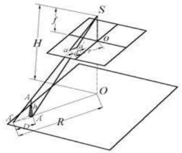
Actually in most practical applications, the image rectification needs to be done before the process of quick mosaicking the images. The height variations of the photographed ground surface result in the displacements of the image feature points from truth and the changes on the scale factor. Furthermore, such errors can be propagated into the process of multi-image stitching. Such a scenario is showed in Figure 1:
Figure 1. The image point displacement due to the surface respectively. Symbols d and D illustrate the displacements. R is the distance between the principal point’s projection and the projection errors are mainly affected by the UAV flight attitude and the height of the photographed ground surface.
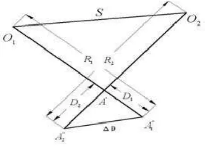
Figure 2. The same object project onto a different frame (Looking down at the surface)
When a strip of images have been processed, the model of the adjacent images is showed in Figure 2, in which A is the object, , are the principal points of the neighbouring images. S is the baseline. , are the object projections with the adjacent images on the surface. The ∆D denotes the error of object height projection with respect to the adjacent images. The function model is illustrated as:
(5)
(6) In Equations (1) and (2), solving the six transformation elements requires only three pairs of homologous points. Actually, redundant homologous points are normally made, thus a least squares estimation procedure is implemented to deal with redundancies. The is expressed as:
(7)
Equation (7) is based on the assumption that the adjacent images are taken at the same attitude. Eventually, the object height projection error in the image coordinate frame can be estimated and evaluated. For instance, when the image features are taken with the scale of 1:25000, the flight attitude is 600 m, the focus length is 24 mm, the baseline is 30 m, the surface height is 40 m, and then the is resolved as 0.085 mm. When the surface height varies to 100 m, the estimated error is 0.24 mm.
As GPS and Inertial Measurement Unit (IMU) can provide initial values of the exterior parameters, the mean values of the object height can be figured out by a photogrammetric process. These values are statistically related to the surface height h, and then the corrections can be estimated from Equation (4). 2.2 Quick Mosaicking UAV Images
Producing seamless mosaicked UAV images can benefit vaious practical applications. An optimal seam line should meet the criterions that the differences of the intensities between the pixels of the two images along the seam line are minimal, and neighboring geometric structures of the pixels along the seam line are most similar (Xing et al 2010). Our method implemented to quick mosaic UAV images with two different
processes in two situations that are the near-flat area and the area with chains of hills.
2.2.1 Quick Mosaicking UAV Images for the near-flat areas
In quick mosaicking UAV images in the near-flat areas, the errors of object height projections may be negligible. Thus, the affine transformation can be directly implemented. One of the adjacent images, e.g., the left image, has to be corrected with the known exterior parameters and vision distortions. The follow-on step in the mosaicking process is the coordinate transformation between the image coordinates and object coordinates, as showed below:
[ ] [ ] (8)
in which X,Y and Z denote the object coordinates, and x,y,z are the image coordinates, R is the rotation matrix. When the left image is nearly lying on the horizontal plane, the neighbouring image (the right image) is processed through Equations (1) and (2) to obtain the six transformation elements ( , ). And then the homogenous points on the right image are translated into the left image coordinate frame. Quick mosaicking the adjacent images can be done. The illustration of such a process is showed in Figure 3:
Figure 3. The homogenous points on the right image are matched with those on the left image
The origin of the image coordinate frame is located on the top left corner for each image. For many strips of images, the stitching processing could be implemented from one side to the other side. If the homogenous points are redundant for Equations (1) and (2), the least squares model is used and showed below:
(9)
(
) (10)
(11) (12) GPS and IMU can provide the exterior parameters. The matching between the geo-referenced homogenous points can be solved while quick mosaicking UAV images is conducted. Thus, instead of image coordinates in the models, the
referenced coordinates can be connected to the geometry models.
2.2.2 Quick Mosaicking UAV Images for the areas with hills
In quick mosaicking the UAV images from the areas with hills, the object height projection errors will have to be considered as such errors will propagate into the image stitching processing. So, according to project process, the bilinear transformation is proposed:
(13) (14) Similarly, the coordinates of one of the adjacent images are transformed into the other image coordinate frame. The geometric rectification of the images is made when the error of projection is large. To achieve a reasonable mosaicking quality, the number of the UAV images in one mosaicking process is limited. Thus, a set of images may be split into several strips. And then different strips of the stitched images can be linked by affine transformations.
3. EXPERIMENTS
The experiments were conducted in 2010, the flying attitude of UAV was 600 meters. The resolution of image can be reached to 3888*2596. GPS sampled with 1HZ. The accuracy of angular data from IMU was 1 degree (Root Mean Square). The accuracy of linear parameter was 10 m to 20 m. The tests focused on residuals and Root Mean Square (RMS) errors of homogenous points for each individual image. If the residual was over 2 times or 3 times larger than the RMS error, the corresponding homogenous point was removed in order to reduce the effect of outliers on the image matching.
The first experiment conducted in the area with hills. The most part of the test field is nearly flat. Some areas are full of hills. The process of quick mosaicking was along the UAV trajectory. The stitched overall image is showed in Figure 4. About 36 individual images have been stitched together and each image was assigned an identification number from the image strip’s left side to the right side.
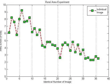
Table 1 and Figure 5 illustrate the results of the RMS errors for each UAV image. The largest RMS error of the image data set was 9.2 pixels, while the smallest one was 2.3 pixels. From the first image to the 13th image, the RMS errors were above 6 pixels.
Figure 4. 36 pieces of images stitched together
Image Identification 1 2 3 4 5 6 7 8 9 10 11 12
RMS (pixel) 6.1 8.2 7.6 5.8 8.0 9.2 7.6 7.7 8.2 6.2 6.7 5.8
Image Identification 13 14 15 16 17 18 19 20 21 22 23 24
RMS (pixel) 6.5 4.3 4.1 4.8 4.8 4.4 4.3 3.9 2.6 4.4 4.7 4.4
Image Identification 25 26 27 28 29 30 31 32 33 34 35 36
RMS (pixel) 3.6 4.8 3.4 4.4 3.1 3.7 2.5 2.6 2.3 2.3 2.8 2.5
Note: The largest RMS Error: 9.2*0.0057mm=0.05mm;
The smallest RMS Error:2.3*0.0057mm=0.013mm; (Pixel Size=0.0057mm)
Table 1. RMS errors of the hill area test for 36 UAV images
Figure 5. The plot of the RMS errors of the hills’ area test for each image
The error distribution pattern in the areas with hills is probably due to the complicated ground surface. In addition, in this test, the UAV flight stability could not be easily achieved. The flight attitude was changing all the time during the test, which also affects the projection of the object heights onto the images. From the 14th image to the last one, the RMS errors were around 3.5 pixels.
The second experiment was conducted in a typical urban area, where the UAV flight attitude was 600 meters. The resolution of images was 4000*3000. The GPS and IMU sensor data were not available. The tested urban area is featured with the flat ground surface that will benefit the image stitching process, but the major height projection error may also come from high-rise buildings. To eliminate the errors of object height projection onto the images, the several procedures were taken to remove the worst homogenous point that has the largest RMS error.
Figure 6. 9 pieces of images stitched together
Image Identification 1 2 3 4 5 6 7 8 9
RMS (pixel) 3.61 4.3 2.4 5.8 3.7 4.2 6.6 7.7 5.4
Note: The largest RMS Error: 7.7*0.0057mm=0.04mm;
The smallest RMS Error :2.4*0.0057mm=0.014mm, (Pixel Size=0.0057mm) Table 2. The RMS errors of the urban test for 9 UAV images
Figure 7. The plot of the RMS errors of the urban test for each image
The UAV images were identified by the numbers from the strip’s left side to the right side. The homogenous points were extracted from the right/left image pairs. The transformation parameters of the left image can be figured out from Equation (1) with the image coordinates of the homogenous points. The big residual errors were removed during the transformation processing, and then the image coordinates of the corresponding points on the right image were computed. Resampling the right image and stitching it with the left image, the mosaicked image was formed from several stitched image pairs, and is shown in Figure 6.
The differences between the test area with hills and the urban test area are that the GPS and IMU data were not used in the urban test. Thus the correction of height projection error cannot be made. The most important point for the urban test was the selection of the initial image which was the first one of the
stitched image strip. During the processing, some big residuals were removed to keep the corresponding points generally lying on the same flat surface. The RMS errors of the urban test were showed in Table 2 and Figure 7. It is noted that the largest RMS error was 7.7 pixels, while the smallest one was 2.4 pixels. There are five pieces of images that have less than 5 pixels of RMS errors, while the RMS errors of the rest images are larger than 6 pixels, which are caused by high rise buildings captured on those images.
When the process of affine transformation was made, the more corresponding points were extracted, the more accurate coordinates could be determined, and thus the impacts of gross errors on the quick mosaic of UAV images were reduced. On the other hand, the correction of big residuals and lowering
the “root mean square” errors in coordinate transformation steps can ensure more precise image stitching. For specific applications like UAV mapping in the areas with hills or in the urban areas with high rise buildings, the process of quick mosaicking UAV images should take a special consideration on the error of object height projection. During the process of quick mosaic, GPS and IMU geo-referencing data for the UAV platform could be used to correct the height error for high rise the correct was against to vector r. If the object height h above the ground surface is close to zero, the can be considered as 0. The higher flight attitude, the better performance of quick mosaicking can be achieved. On the other hand, if the baseline is short, or if the overlaps of images are large, the errors of object height projection will be reduced.
4. CONCLUTIONS
The traditional methods for UAV image processing have no capability of effective mapping in near real time modes. More efficient methods for quick mosaicking UAV images have been investigated for many years to deal with fast mapping applications, such as disaster monitoring, human rescue. This paper has proposed a new UAV image mosaicking method which uses the homogenous points extracted from the imaging stitching. The error of projection with respect to object height should be corrected to obtain an acceptable accuracy of the stitched images. For near-flat surfaces, the affine transformation can be directly used to translating the image coordinates from one image to the adjacent image frame. For the area with hills and the urban areas with high rise buildings, geometric rectification of images is necessary to ensure that the homogenous points are correctly matched. For general applications of UAV image quick mosaicking, the scales of the captured images vary from 1:10000 to 1: 50000, and the accuracy of the stitched image could reach the level of 1 meter in the object space.
REFERENCE
Cheng, Y., Xue, D. & Li, Y. 2007. "A fast mosaic approach for remote sensing images", International Conference on Mechatronics and Automation on IEEE, August 5 - 8, 2007, from UAV, IEEE Proceedings of Fourth International Conference on Fuzzy Systems and Knowledge Discovery, 24-27 Aug. 2007, Haikou, China, pp.11- 15.
Marenchino, D. 2009 reported on Horizon. “Low Cost UAV for the Environmental Emergency Management Photogrammetric procedures for Rapid Mapping Activities” http://www.dirap.unipa.it/autec/uploads/YvC2c2qgRDbdutX5n Images from Unmanned Aerial Vehicles", International Conference on Electrical and Control Engineering, June 25-June 27, Wuhan, China
Yahyanejad, S., Wischounig-Strucl, D., Quaritsch, M. & Rinner, B. 2010. "Incremental Mosaicking of Images from Autonomous, Small-Scale UAVs", Seventh IEEE International Conference on Advanced Video and Signal Based Surveillance. Zhou, G. 2009. "Near real-time orthorectification and mosaic of small UAV video flow for time-critical event response." Geoscience and Remote Sensing, Transactions on IEEE , vol. 47, No.3,pp739-747.