Load and Resistance Factor Design (LRFD) for Highway Bridge Substructures
Teks penuh
Gambar
Dokumen terkait
Correlation analysis was used to determine how the load consumption is related to the forecasting variables (model inputs), and hypothesis test was used to justify the
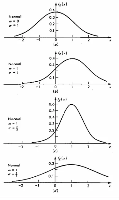
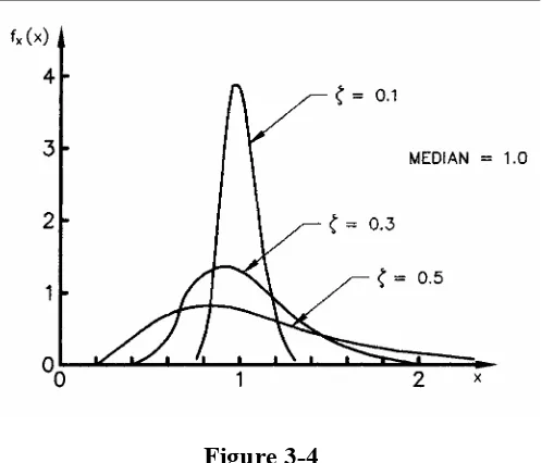
Gambar 1 mewakili variabilitas sifatsifat struktural dari produkproduk kayu yang telah didekati dengan distribusi normal standar. Gambar
In some cases, it may be appropriate to include the wind load effects directly in the main superstructure analysis. Wind load may have a more pronounced influence on the girder design
F t Nominal tensile strength of bolt from LRFD Specification Table J3.2, ksi F u Specified minimum tensile strength of the type of steel being used, ksi F v Nominal shear strength
Gde Widiadnyana Merati, Guru Besar Madya Jurusan Teknik Sipil ITB, “Perencanaan Struktur Baja berdasarkan konsep LRFD”5. M.Eng, “Grafik dan Tabel Perhitungan Beton Bertulang”
Tugas Akhir ini merupakan salah satu persyaratan yang harus ditempuh dalam menyelesaikan Pendidikan Tingkat Sarjana (Strata 1) Jurusan Teknik Sipil Fakultas Teknik
Dynamic results of the proposed controller during full-load to no-load change, reference voltage, output voltage and current, inverter output current (1 A/div), inverter output
5.2 Curved Box Girder Bridges The AASHTO LRFD Design Specifications provide a set of live load distribution factor formulas for determining the distribution of bending moment effects
