Autonomous Intelligent Systems Group, Institute for Computer Science VI, University of Bonn, Germany {holz, nieuwenhuisen, droeschel, schreiber, behnke}@ais.uni-bonn.de
KEY WORDS:Autonomous UAVs, Multimodal Sensor Setup, 3D Laser Scanner
ABSTRACT:
Limiting factors for increasing autonomy and complexity of truly autonomous systems (without external sensing and control) are onboard sensing and onboard processing power. In this paper, we propose a hardware setup and processing pipeline that allows a fully autonomous UAV to perceive obstacles in (almost) all directions in its surroundings. Different sensor modalities are applied in order take into account the different characteristics of obstacles that can commonly be found in typical UAV applications. We provide a complete overview on the implemented system and present experimental results as a proof of concept.
1 INTRODUCTION AND RELATED WORK
Unmanned aerial vehicles (UAVs) are particularly useful in ap-plications where the operating site cannot be reached by ground vehicles or applications that require an aerial view of the whole scene. In the context of a larger project on three-dimensional se-mantic mapping of inaccessible areas and objects, we aim at de-veloping an unmanned aerial vehicle that is able to autonomously navigate in suburban areas and especially in the (close) vicinity of buildings, vegetation and other possibly dynamic objects. In par-ticular, we focus on fast and reliable perception of (even small) obstacles in the vicinity of the UAV. In this paper, we describe the hardware design of our platform including the sensor setup and the applied methods for robustly detecting obstacles, as well as for planning the UAV’s motion in order to reach goal poses while reliably avoiding collisions.
The application of UAVs in recent robotics research varies es-pecially in the level of autonomy ranging from basic hovering and position holding (Bouabdallah et al., 2004) over trajectory tracking and waypoint navigation (Puls et al., 2009) to fully au-tonomous navigation (Grzonka et al., 2012). Limiting factors for increasing autonomy and complexity of truly autonomous sys-tems (without external sensing and control) are limited onboard sensing and limited onboard processing power.
Particularly important for fully autonomous operation is the abil-ity to perceive obstacles and avoid collisions. Most autonomous UAVs, however, cannot adequately perceive their surroundings and autonomously avoid collisions. Instead, collision avoidance is often restricted to the two-dimensional measurement plane of laser range finders (Grzonka et al., 2012) or the limited field of view of (forward-facing) cameras, or generally avoided, e.g., by flying in a certain height when autonomously flying between waypoints). Tomi´cet al. present an autonomous UAV that per-ceives its environments using a stereo camera pair mounted for-wards and a 2D laser range scanner mounted horizontally (Tomi´c et al., 2012). Still, their perceptual field is limited to the apex an-gle of the stereo camera pair (facing forwards), and the 2D mea-surement plane of the scanner when flying sideways. They do not perceive obstacles outside of this region or behind the vehicle. We aim at perceiving as much of the surroundings as possible in order to obtain almost omnidirectional obstacle detection.
The remainder of the paper is organized as follows: After an overview over the UAVs hardware and a description of the sensor
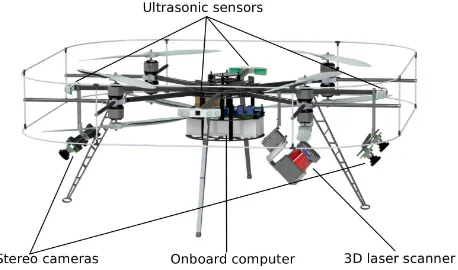
Figure 1: CAD model of our UAV with motor arrangement and sensor setup: continuously rotating 3D laser range finder, two stereo camera pairs and a ring of ultrasonic distance sensors.
setup in the next section, we will detail the communication infras-tructure in Sec. 3. In Sec. 4 we describe our laser-based obstacle detection, followed by visual and ultrasonic obstacle perception in Sec. 5, and Sec. 6, respectively. In Sec. 7 we present our state estimation filter. Finally, we show applications of the UAV and conclude the paper.
2 SYSTEM DESIGN AND SENSOR SETUP
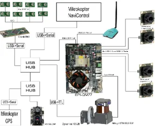
Figure 2: Schematic overview of the onboard communication on our UAV. The main compute unit is connected to a plurality of sensors, i. e., two stereo-camera pairs, the 3D laser scanner, eight ultrasonic sensors (via microcontroller board), an optical flow camera, and a GPS sensor. Our UAV is controlled using an extended version of the MikroKopter debug and control protocol. The downlink to a base station computer is provided by a high-power wireless adapter.
ground and can—depending on the lighting conditions—measure velocities relative to the ground-plane with more than100 Hz.
Our platform is based on the open sourceMikroKopteroctocopter kit, with a co-axial arrangement of rotors (see Fig. 1). The on-board computer (Intel Core i7, 8GB RAM) has ample computing power for tasks of advanced complexity and the variety of sen-sors. It is based on the Avalue EPI-QM77 and hosts two serial ports, two USB 2.0 ports, and four USB 3.0 ports. Under maxi-mum load it consumes60 Wwhich is negligible compared to the power consumption of the eight motors when flying. It is both small (115 mm×165 mm) and light-weight (180 g). CPU, CPU cooler, RAM, and SSD drive increase the weight of the onboard computer by another260 g.
The platform is powered by a Turnigy nano-tech lithium polymer battery pack with8000 mA h. It allows for high velocities (with high25 Cto50 Cdischarge) and flight times of up to10 min. When standing on the ground (with motors turned off), the system can operate for hours. The battery pack has a weight of0.9 kg. Overall, our system has a total weight of4.8 kg and a size of 85 cm×85 cm×35 cm(length×width×height).
3 COMMUNICATION
We communicate with the vehicle by means of serial communica-tion and a simple protocol originally intended for debug use (Sa and Corke, 2011). For the purpose of fully autonomous naviga-tion and control over the UAV, we have extended both firmware and protocol as well as the original hardware setup (see Fig. 2).
Depending on the application, we plan to use different GPS sen-sors. In order to gain this flexibility, we have directly attached the built-in GPS to the onboard computer. We use the binary u-blox protocol. It is not only more efficient than the ASCII variant usually used for the MikroKopter but also used by our other GPS sensors and thus allows for easy exchange of components.
Firmware and protocol have been extended to also communicate accelerometer and gyroscope measurements (for all three axes), user inputs (stick orientation and buttons from the remote con-trol) as well as internal status information. The user inputs are of particular interest for us as we plan to learn dynamic motion models to further improve the UAV’s local navigation capabili-ties (Nieuwenhuisen et al., 2013).
For the communication between different components of our soft-ware control architecture, we employ the communication infras-tructure of the Robot Operating System ROS (Quigley et al., 2009). Those processing pipelines with large amounts of data and almost batch-like processing like the laser pipeline and the visual obsta-cles pipeline presented in the following are implemented using nodelets and efficient intraprocess communication, respectively.
In order to retrieve higher level mission plans and exchange in-formation with advanced components on a base station computer we use a WiFi link. Due to possible limitations in bandwidth and signal quality, we focus communication on a fraction of the data that is communicated between components on the onboard com-puter. We implemented this focused communication by means of two ROS master cores running in parallel—one on the onboard computer and one on the base station. An additional node on the base station picks up local data topics and services that are to be exchanged and advertises to the remote ROS master on the on-board computer and vice versa. All components on the onon-board computer are designed to not fail in case of communication prob-lems or full connection loss.
(a) (b)
(c) (d)
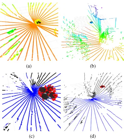
Figure 3: Examples of acquired laser scans with points colored by height (a+b) and laser-based ground plane and height estima-tion (c+d): After filtering out measurements on the robot (red points), we estimate the dominant horizontal plane (blue points), and compute its distance to the robot as an height estimate. Ob-stacles other than the ground are colored black.
4 LASER-BASED OBSTACLE DETECTION
Our primary sensor for obstacle avoidance is a continuously ro-tating 3D laser scanner that provides an almost omnidirectional view of the surroundings. Full 3D point clouds are acquired and processed with up to2 Hz.
4.1 Continuously Rotating 3D Laser Scanner
Our main sensor consists of a Hokuyo UTM-30LX-EW 2D LRF, mounted on a bearing with a slight tilt angle. The bearing is con-tinuously rotated by a Dynamixel MX-28 servo actuator to gain a three-dimensional field of view (FOV). The 2D LRF is connected to the system by a slip ring, allowing for seamless rotation of the sensor. The whole setup is pitched downward by45◦which al-lows to maximize the FOV and to minimize the blind spot of the sensor.
Calculating a 3D point cloud from the distance measurements ne-cessitates the exact orientation of the bearing. This information can be derived from the actuator’s encoder but results in a com-munication overhead with the Dynamixel actuator and is a source for artifacts in the 3D scan in case of varying communication la-tencies. Hence, we estimate the orientation of the bearing based on the encoder’s position, assuming a constant rotational velocity.
The Hokuyo UTM-30LX-EW is able to measure up to three echoes of a single emitted light pulse. The number of echoes a light pulse reflects depends on the surface of the object, i.e. shape and reflec-tivity. For example, transparent material, vegetation or edges of buildings often reflect more than one echo. Hence, multi-echo detection is ideal for outdoor applications.
4.2 Scan Acquisition
For further processing of the acquired 3D data we form distinct point clouds from the continuous data stream of the rotating laser range scanner. We keep track of the rotation angle and start aggre-gating laser range scans to form a new 3D point cloud every half
(a) CAD drawing (b) Photo of the scanner
Figure 4: CAD drawing (a) of the continuous rotating laser scan-ner with the two rotation axis with the Hokuyo 2D LRF mounted on a bearing and rotated around the red axis and photo of the assembled laser scanner (b).
rotation. Since movement of the sensor during acquisition leads to a distortion of the 3D scan, we use the estimated transforma-tion between two aggregated 3D scans to deskew it. Therefore the rotational and translational parts of the displacement are dis-tributed over the single scan lines of the scan. For an acquired 3D scan, the transformation that has been estimated for the pre-vious scan is used as an initial guess and deskewed again after registration.
4.3 Self Filtering and Removing Erroneous Measurements
Because of the wide angle of the laser range scanner, a consid-erable amount of points is either measured directly on the robot itself, or caused by occlusion effects. We filter out such measure-ments by applying a simplified robot model for estimating which measurements coincide with the robot’s body parts. Referring to Fig. 3, we distinguish between measured points on the aerial ve-hicle and measured points belonging to obstacles in the robot’s vicinity.
4.4 Laser-based Height Estimation
Height estimates based on onboard air pressure sensors are noisy and error-prone due to the turbulences created by the UAV itself. In order to obtain an accurate height estimate, we first compute the set of points below the robot and then find the most dominant (horizontal) plane for these points. We define a frustum that cor-responds to the apex angles of the optical flow camera mounted under the robot and pointed downwards. For the points within the frustum, we apply an approach based on the M-Estimator sample consensus (MSAC) (Torr and Zisserman, 2000). After finding the most dominant plane model, we determine the set of inliers (from the complete laser scan) for the found plane model, and then refine the model by fitting a plane through all inliers. We use the distance of the robot to the estimated ground plane as a height estimate within our state estimation approach. The run-times for scan acquisition, filtering and ground plane estimation as described above lie in the range of milliseconds. Fig. 5 shows a comparison of laser-based height estimation to the barometer and an ultrasonic height estimate.
5 VISUAL OBSTACLE DETECTION
(a)
(b)
Figure 5: Different height estimates: (a) at low heights the barom-eter is unreliable due to turbulences; (b) at heights above 5 m the ultrasonic distance sensor drops out.
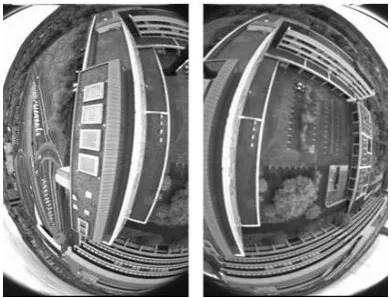
Figure 6: Images taken by one forward-facing and one backward-facing camera during flight. The fields of view cover the entire semi-sphere around and below the robot.
Visual obstacle detection is based on interest points, which are ex-tracted and tracked in the video streams of the individual cameras using the OpenCV implementation of the KLT feature tracker and matched across the cameras, if possible. Beneath obstacle detec-tion the tracked features are used for visual odometry, a topic we will not discuss in this paper. For visual obstacle detection we use the known mutual orientations between the cameras within a stereo pair, which is determined in advance as described in (Schneider and F¨orstner, 2013), to determine the coordinates of the matched feature points within the camera frame at every time of exposure via triangulation.
6 ULTRASONIC SENSORS
As neither the laser point cloud nor the visual obstacles are dense, and transparent obstacles cannot be measures optically, our UAV is equipped with eight ultrasonic sensors covering the near space around it. These sensors detect smaller obstacles in the vicin-ity of the robot, e.g., wires and tree branches. We use a total of eight Devantech SRF10 ultrasonic sensors. They have a maxi-mum range of6 mand a minimum range of4 cm. Distances are
(a) CAD model with illustrated cones (b) Photo
Figure 7: Setup and mounting of ultrasonic sensors.
(a) CAD model (b) Close-up
Figure 8: Setup and mounting of stereo camera pairs.
measured with40 Hzand in steps of43 mm. Ultrasonic sensors are particularly well suited for detecting close obstacles. In our setup, they are used as a fallback for dynamic obstacles suddenly appearing in the UAV’s vicinity. Furthermore, their measurement principle with the wide sonar cone allows for perceiving obstacles that are hard to detect otherwise, e.g., wires and tree branches, as well as transparent obstacles such as windows.
Referring to Fig. 7, the ultrasonic sensors are mounted in a ring around the UAV in a star-like pattern with one pair of sensors at each of the four riggers of the frame. The range measurements are sequentially read using an AVR ATmega2560. It is connected to the onboard computer via USB (and an USB serial converter).
We filter out erroneous measurements by examining a sequence of measurements for each of the ultrasonic sensors, and only take a measurement into account for collision avoidance when it ap-pears stable over several readings. In all our experiments, incor-rect measurements were sparse and not persisting over multiple range readings.
In order to asses the accuracy and characteristics of the sensors, we conducted a set of experiments. As can be seen in Fig. 9, the distance measurements are quite accurate and do not consid-erably deviate from ground truth if the measurement angle to-wards a surface is not too shallow. In addition, we successfully tested their ability to detect transparent objects by taking distance measurements to Plexiglas plates where beams of the range scan-ner went through without causing reflections and correct distance measurements, respectively.
7 STATE ESTIMATION
0
Figure 9: Experimental evaluation of ultrasonic range readings in different situations: varying distances to a cylindrical pipe (left) and to a perpendicular wall (middle) with ground truth (black line), and distances to a wall with varying measurement angle.
Filter (EKF). Our implementation is based on the Bayesian Filter-ing Library (Gadeyne, 2001). In this section we detail the fused sensor information and our state estimation.
We incorporate direct velocity measurements in the plane from an optical flow camera (Honegger et al., 2013) at 100 Hz. The velocities are calculated directly in the camera module. These noisy measurements provide us with a good velocity estimate af-ter filaf-tering. Due to the necessary scale estimation the distance to the ground is measured by an ultrasonic sensor. This restricts the operational height over ground of this sensor to5 m. Fur-thermore, to work reliably the ground plane has to be textured. Additionally, we incorporate the height measurements of the on-board ultrasonic sensor of the camera module.
At larger heights, we have to use other means of velocity mea-surements. We incorporate pose and velocity estimates com-ing from visual odometry uscom-ing our fisheye cameras with PTAM (Klein and Murray, 2007) at approximately20 Hz. Currently, our filter can be linked to two sources of visual odometry. PTAM es-timates an allocentric 6D pose of the UAV that we use to calculate ego-velocities for filtering.
Another source of position and velocity information is the on-board GPS receiver. The UAV is equipped with an u-blox LEA-6S consumer GPS chip. We incorporate the absolute position of the UAV and planar velocities into our filter. This is the only source of an absolute position in a global frame, but at a low rate of up to5 Hz.
To get an accurate height estimate, we fuse measurements from a barometric sensor, the ultrasonic sensor, laser range measure-ments, and visual odometry. The barometric measurements are available at a high rate and in every situation. In the initialization routine of the UAV, the sensor is calibrated and initialized with zero height. The provided height measurements are well suited to estimate relative height changes, but the absolute height is sub-ject to a drift over time. To cope with the drift, we incorporate the other sensors. The ultrasonic sensor measures the absolute height over ground at a high rate and with centimeter-level accuracy, but only up to an altitude of5 m. Up to an altitude of30 m, we use laser-based height estimation (cf. Sec. 4.4). As we extract this information from the 3D measurements of the rotation laser, this information arrives at a rate of2 Hz.
8 INTEGRATION, EXPERIMENTS AND RESULTS
We represent the surrounding environment as a three-dimensional grid map. Its purpose is to aggregate the multi-modal sensory
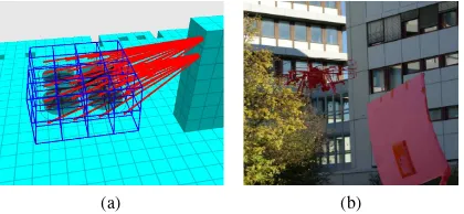
in-(a) (b)
Figure 10: Visualization of a 3D grid map and repelling forces induced by obstacles in range (a) and a photo (b) taken during an experiment where the hovering UAV avoided collisions with a dynamic obstacle approaching the vehicle (UAV and obstacle colorized for better visibility).
formation in order to 1) compensate for the limited view field and characteristic shortcomings of individual sensors, and 2) have a compact representation for planning collision-free paths and mo-tions of the UAV and to localize it with six degrees of freedom during its motion. We developed efficient approaches for register-ing 3D laser range scans and constructregister-ing the 3D map (Droeschel et al., 2013) as well as for planning collision-free paths in the map (Nieuwenhuisen et al., 2013). All components are integrated into a software framework based on the Robot Operating System ROS and run on the onboard computer. In addition, the UAV communicates with a base station for sending sensor readings and receiving mission plans.
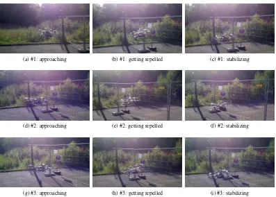
As shown in Figures 10 and 11, we evaluate the reliability of our obstacle detection and collision avoidance approach in both real-world and simulated environments. In the experiment setup shown in Fig. 11, the autonomous UAV was commanded to fly forwards with a constant velocity. In all three shown experiments, the UAV could detect the fence and avoided a collision. In other experiments, the UAV was commanded to hover in a stable po-sition or to fly constant velocities in certains directions and got approached by one or more persons and other moving obstacles from different directions (Figure 10.b). In all cases, the UAV was able to adapt its motion to avoid a collision with the obstacle(s).
9 CONCLUSION AND FUTURE WORK
omnidirec-(a) #1: approaching (b) #1: getting repelled (c) #1: stabilizing
(d) #2: approaching (e) #2: getting repelled (f) #2: stabilizing
(g) #3: approaching (h) #3: getting repelled (i) #3: stabilizing
Figure 11: Photos taken during three experiments. Videos are available at: http://www.ais.uni-bonn.de/MoD.
tional field of view, but only provides sparse measurements at considerably low frame rates (2 Hz). Two stereo camera pairs pointed in the main movement directions provide additional sparse obstacles at high frame rates. Ultrasonic sensors allow for detect-ing even small and hard to detect obstacles such as tree branches or cables at high frame rates, as well as transparent obstacles such as windows. As shown in experimental results, the autonomous UAV can avoid collision with dynamic obstacles (not necessarily intersecting a certain 2D laser range scanning plane as in related works).
In future work, we plan to further extend the system and increase autonomy by integrating fully autonomous navigation and the ex-ecution of higher-level mission plans such as exploration and in-spection tasks.
ACKNOWLEDGMENTS
This work has been supported partially by grants BE 2556/7-1 and BE 2556/8-1 of German Research Foundation (DFG).
REFERENCES
Bouabdallah, S., Murrieri, P. and Siegwart, R., 2004. Design and control of an indoor micro quadrotor. In: Proc. of the IEEE international Conf. on Robotics and Automation (ICRA), New Orleans, LA, USA, pp. 4393–4398.
Droeschel, D., Schreiber, M. and Behnke, S., 2013. Omnidirec-tional perception for lightweight uavs using a continuous rotating 3D laser scanner. In: Proc. of the 2nd Conference on Unmanned Aerial Vehicles in Geomatics (UAV-g).
Gadeyne, K., 2001. BFL: Bayesian Filtering Library. Available online athttp://www.orocos.org/bfl.
Grzonka, S., Grisetti, G. and Burgard, W., 2012. A fully au-tonomous indoor quadrotor. IEEE Transactions on Robotics 28(1), pp. 90–100.
Honegger, D., Meier, L., Tanskanen, P. and Pollefeys, M., 2013. An open source and open hardware embedded metric optical flow cmos camera for indoor and outdoor applications. In: Proc. of the IEEE international Conf. on Robotics and Automation (ICRA).
Klein, G. and Murray, D., 2007. Parallel tracking and mapping for small AR workspaces. In: Proceeding of the IEEE and ACM International Symposium on Mixed and Augmented Reality (IS-MAR).
Nieuwenhuisen, M., Schadler, M. and Behnke, S., 2013. Pre-dictive potential field-based collision avoidance for multicopters. In: Proc. of the 2nd Conference on Unmanned Aerial Vehicles in Geomatics (UAV-g).
Puls, T., Kemper, M., Kuke, R. and Hein, A., 2009. Gps-based position control and waypoint navigation system for quadro-copters. In: Proc. of the IEEE/RSJ Int. Conf. on Intelligent Robots and Systems (IROS), St. Louis, MO, USA, pp. 3374– 3379.
Quigley, M., Conley, K., Gerkey, B. P., Faust, J., Foote, T., Leibs, J., Wheeler, R. and Ng, A. Y., 2009. Ros: an open-source robot operating system. In: ICRA Workshop on Open Source Software.
Sa, I. and Corke, P., 2011. Estimation and control for an open-source quadcopter. In: Proc. of the Australasian Conference on Robotics and Automation (ACRA), Melbourne, Vic., Australia.
Schneider, J. and F¨orstner, W., 2013. Bundle Adjustment for Om-nidirectional Camera Systems with Points at Infinity Including System Calibration. Z. f. Photogrammetrie, Fernerkundung und Geoinformation. to appear.
Tomi´c, T., Schmid, K., Lutz, P., Domel, A., Kassecker, M., Mair, E., Grixa, I., Ruess, F., Suppa, M. and Burschka, D., 2012. To-ward a fully autonomous uav: Research platform for indoor and outdoor urban search and rescue. Robotics Automation Maga-zine, IEEE 19(3), pp. 46–56.