TRAFFIC LIGHT DETECTION USING CONIC SECTION GEOMETRY
S. Hosseinyalmdarya∗, Alper Yilmaza
aPhotogrammetric Computer Vision Laboratory (PCVLab),
Civil and Environmental Engineering and Geodetic Science Department, The Ohio State University 2070 Neil avenue, Columbus, OH, USA 43210 - (hosseinyalamdary.1, yilmaz.15)@osu.edu
Commission I, WG I/Vb
KEY WORDS:Traffic Light Detection, Conic Section, Homography Transformation, OpenStreetMap
ABSTRACT:
Traffic lights detection and their state recognition is a crucial task that autonomous vehicles must reliably fulfill. Despite scientific endeavors, it still is an open problem due to the variations of traffic lights and their perception in image form. Unlike previous studies, this paper investigates the use of inaccurate and publicly available GIS databases such as OpenStreetMap. In addition, we are the first to exploit conic section geometry to improve the shape cue of the traffic lights in images. Conic section also enables us to estimate the pose of the traffic lights with respect to the camera. Our approach can detect multiple traffic lights in the scene, it also is able to detect the traffic lights in the absence of prior knowledge, and detect the traffics lights as far as 70 meters. The proposed approach has been evaluated for different scenarios and the results show that the use of stereo cameras significantly improves the accuracy of the traffic lights detection and pose estimation.
1. INTRODUCTION
The traffic light detection and its state recognition is essential for quickly emerging fully automated vehicles. The state of traffic light includes red, yellow, and green signals that authorizes the right of way and consequently, correctly recognizing the state of traffic light is crucial for safe driving. Although many sensors are applied in fully automated vehicles, the recognition of the state of traffic light is feasible using color cameras on the platform. Thus, we focus on the traffic light detection and its state recognition using color cameras mounted on the platform.
This is still a challenging problem due to the fact that there are many variations of traffic lights. For instance, the shape of traffic lights are not always identical and traffic light lenses can be in-stalled horizontally or vertically. Moreover, size of traffic lights may change from one country to another or from one state to an-other. Traffic light may be installed on a pole or suspended and they can be located on the right or left side of the road. Moreover, there may be one traffic light for all the lanes or multiple traffic lights for each lane.
In addition, camera sensors are imperfect and the environment may not be benign to capture good images. The images are al-ways noisy especially when low cost cameras are used. Also, motion blurriness deteriorates the image quality when the plat-form moves. Additionally, camera lens distortion may change geometry of the traffic light if it is not calibrated. In addition, the traffic light has low resolution when it is far from the camera and the low resolution traffic lights may not maintain the shape cue. Furthermore, the lighting situation may create problems that impede correct detection of the traffic lights. For instance, the images can be overexposed during sunrise and sunset when the sun is low. Also, colors are not observed identical in daylight and nightlight.
Knowing these problems, traffic light detection is not a trivial task. In this paper, the color and shape cues are used to detect
∗Corresponding author
the traffic lights. In addition, prior knowledge of existence of a traffic light is applied using GIS maps. However, the GIS maps may not be comprehensive and accurate and the traffic lights may not to be accurately localized in the maps. This paper provides an approach to detect traffic lights considering the changes in color and shape cues due to different error sources and inaccurate GIS maps.
In this paper, we apply conic section geometry to detect the traffic lights since conic sections are primitive geometry shapes with multiple properties. Traffic light lens is a circular object which is a conic section. Additionally, conic sections are preserved under perspective geometry, that is, the projection of conic section is a conic section. Conic sections are represented by matrices and conic section geometry is easy to manipulate.
1.1 Previous work
The traffic light detection remains an unsolved problem in fully automated vehicles. More successful works apply prior knowl-edge such as GIS maps to initialize their search space and im-prove the traffic light detection results. Levinson et al. (Levinson et al., 2011b, Levinson et al., 2011a) have assumed that the traffic lights can be retrieved from databases such as Google Maps and the search space of traffic lights will be reduced knowing their po-sition. Fairfield and Urmson (Fairfield and Urmson, 2011) have also considered the use of prior maps to predict the location of traffic lights in images. Their GIS maps are fairly accurate and their results show that the use of prior information improves the traffic light detection accuracy. However, these databases are not publicly available in vector format. One of the spatial databases is OpenStreetMap (OSM) which is a vector based GIS database, has world coverage, and is publicly available. This database does not guarantee accurate features and these features may be positioned far from their actual location and even some of the features may be erroneously excluded in the database. OSM has been used in this paper to predict the existence of the traffic lights.
strong constraint to detect the traffic lights. The circular Hough transform is applied to detect the traffic signs (Caraffi et al., 2008, Huang and Lee, 2010) that may be applicable to traffic lights too. However, the use of Hough transform is computationally expen-sive and it may not be applicable for real time applications. Conic section geometry has been extensively studied for many years and it has been used for stereo, motion, and pose estimation (De Ma, 1993). It has been shown that the pose of the camera can be es-timated with respect to the object by observing conic sections of the object (Kannala et al., 2006). In this paper, the use of conic sections obtains a strong geometric constraint to detect the traffic lights and their pose.
Furthermore, color cue plays an important role in every traffic light detection. As previously mentioned, the color of traffic lights can be changed due to different lighting situations. Dif-ferent color spaces have also been investigated to more robustly detect the traffic lights (John et al., 2014) and multiple expo-sure images are tested to rigorously detect traffic lights in dark and bright environments (Jang et al., 2014). Diaz-Cabrera et al. (Diaz-Cabrera et al., 2015) claim that color segmentation using fuzzy clustering can improve the traffic light detection results. In this paper, Hue, Saturation, Luminance (HSL) color space is used to detect the traffic lights since it is more resilient to illumination as opposed to Red, Green, Blue (RGB) color space.
The spatial constraint also restrict the position of traffic lights and it can be used to remove false positive detection results that do not follow certain height characteristics. For instance, Siogkas et al. (Siogkas et al., 2012) apply the fact that the traffic light should be above the horizon and they reduce the search space for the traffic lights detection. Finally, characteristics of the traffic light box have been used and several classifiers have been trained to detect these boxes. Wang et al. (Wang et al., 2011) have used the template matching algorithm to detect the traffic light boxes. Also, a few papers, such as (Levinson et al., 2011b, Levinson et al., 2011a), have used machine learning approach to detect the traffic light boxes.
2. METHODOLOGY
This section explains how the visible traffic lights are selected and retrieved from GIS maps. The projection of visible traffic lights into image is not sufficient to initialize search space. Prior knowledge based approaches are not accurate enough when in-accurate GIS maps are used. We apply conic section geometry to detect traffic lights using mono and stereo cameras. The pose of the detected traffic light can be estimated with respect to the camera coordinate system using conic section geometry.
2.1 Visible traffic lights from database
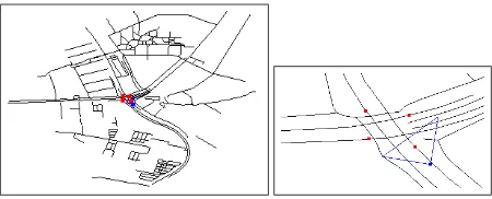
Let’s assume that the sensors installed on the platform have been calibrated and the lever arms and boresights of the sensors have been specified. Therefore, the observations are converted to a uni-fied coordinate system which is camera coordinate system here. The integrated GPS/IMU navigation system provides position and orientation of the platform and its solution is accurate as long as the GPS signals are not blocked. Knowing absolute position of the platform enables us to retrieve the information of the nearby traffic lights from available databases such as OpenStreetMap (OSM). Figure 1 shows the position of the platform in blue, the road links in black and the traffic lights in red, for 500 meters within the vicinity of the platform. The neighborhood of the plat-form is zoomed and the visibility of the camera mounted on the platform is shown by a blue triangle.
Figure 1: Left: the road links and traffic lights (red points) in the vicinity, 500 meters×500 meters, of the platform (blue point). Right: the traffic light which is within the region of interest is selected from OpenStreetMap. The region of interest, which is the field of view of the camera up to 70 meters, is shown in blue triangle.
The traffic lights that are visible in the image and are close to the platform should be retrieved from OSM. The absolute position estimated by GPS is used to find the adjacent traffic lights. In addition, the orientation of the platform estimated by IMU and the field of view of the camera, here90◦
, are used to find the visible traffic lights.
2.2 Projection of the visible traffic lights into image
If two dimensional position of a traffic light is retrieved from GIS maps, three dimensional position of the traffic light,X, is pro-vided assuming the height of the traffic light is known. In order to estimate the image position of traffic lights, projection ma-trix,P, should be estimated. The projection matrix maps three dimensional position of the traffic light into two dimensional im-age space. Two dimensional imim-age coordinates,x, is estimated such that
x=PX. (1)
The projection matrix can be calculated using rotation matrix and translation vector of the traffic light in the camera coordinate sys-tem. Let’s assume that Rco and tc are the rotation matrix and translation vector between the traffic light coordinate system and the camera coordinate system in the camera coordinate system.
P=K[Rc|tc]. (2)
If the camera is calibrated before the operation, the calibration matrix,K, is known. The rotation matrix can be brought to the camera coordinate system, such that
Rc=RciR i
nRn, (3)
whereRciis called boresight between the camera and IMU sensors and it is estimated from the calibration procedure. The rotation matrix between the traffic light coordinate system and the camera coordinate system in global coordinate system isRn. The trans-lation vector,tn, is the difference of the traffic light position and camera position in the global coordinate system and it can be con-verted to the translation vector in the camera coordinate system. The translation vector in global coordinate system is transferred to the camera coordinate system such that
wheretci is the lever arm between IMU and camera sensors and it is estimated from calibration procedure. If the GIS database and navigation system are fairly accurate, the projected position of the traffic light can be used to initialize the search space of the traffic lights. Generally speaking, the direction and height of the traffic lights are not stored in GIS databases. In addition, the traffic light is projected as a point and its size is not known. Moreover, the information of traffic lights may not be correctly collected and stored in GIS database. Therefore, reducing the search space of the traffic lights may lead to incorrect traffic light detection especially for inaccurate GIS databases such as OSM.
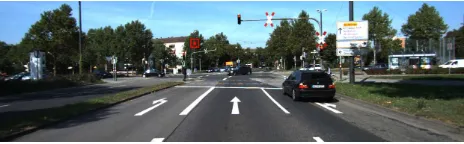
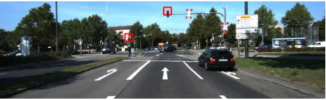
The position of visible traffic lights are retrieved from OSM and projected into image space in Figure 2. There are a few problems if the search space is initialized using the projected traffic light. First, there are multiple traffic lights in the image, whereas the traffic lights are marked as one feature in OSM. Second, the size of the traffic light is not known in the image space and therefore, different scales of the traffic lights should be searched.
Figure 2: The projection transformation of the traffic light is approximated using the position of the traffic light in Open-StreetMap. The projected traffic light lens into the image space is shown with a circle and a rectangle is drawn around it for better visualization.
2.3 Traffic light detection using mono camera
The traffic light lens is circular on a plane. Therefore, the traffic light lens is a conic section and it follows the conic section ge-ometry. Conic sections are closed form, compact, easy to manip-ulate shapes that have a symmetric matrix representation. Under perspective geometry, the circular lens will be seen as an ellipse. Let’s assume that the circular lens is a conic section,Cand its image is an ellipse which is still a conic section,C′in the image space. Since the traffic light is assumed to be planar, transforma-tion between the traffic light lens and its image is homography transformation. Therefore, the homography transformation,H, is used to mapCintoC′such that
C′=H−⊤kCH−1, (5)
Equation (5) estimates the homography transformation up to scale andkis the scale of the homography transformation. Let’s as-sume that the traffic light lens radius isr, the conic section in the traffic light lens plane is a circle represented by a symmetric matrix, such that
C=
1
r2 0 0
0 1
r2 0 0 0 −1
. (6)
The rotation matrix,R, is composed of three column vectors,R= [r1,r2,r3]. The homography transformation is calculated such
that
H=K[r1r2tc] =KRT, (7)
whereT=
1 0 −t1
0 1 −t2
0 0 −t3
,to= [t1t2t3]⊤is the translation vec-tor in the traffic light (object) coordinate system andtc=−Rto. Replacing the conic section,C, in (6) and homography transfor-mation, H, in (7) into (5) provides conic section in the image space,C′. By inverting (5), the conic section in image space is converted into the conic section in the traffic light coordinate sys-tem, such that
kC=H⊤C′H. (8)
Replacing (7) into (8), the homography transformation is esti-mated, such that
kC=T⊤R⊤K⊤C′KRT. (9)
Let’s moveTto the left side of (9) such that
kT−⊤CT−1=R⊤K⊤C′KR. (10)
If two sides of (10) are equal, their eigenvalues are equal too. If
λ1,λ2, andλ3 are the eigenvalues ofK⊤C′K, it has been shown that (De Ma, 1993)
λ1λ2λ3=−
k3 t2
3r4
, (11)
λ1λ2+λ1λ3+λ2λ3=k2
d2−2r2 t2
3r4
, (12)
λ1+λ2+λ3=k
d2+t2 3−r2
t2 3r2
, (13)
whereris the radius of the traffic light lens andd2=t12+t22+t23 is the distance between the camera and traffic light coordinate systems. Whent3anddare calculated, the choice oft1andt2is not important since the traffic light lens is a circle and it should only be chosen to the extent thatd2=t21+t22+t23.
Two sides of (10) are decomposed to their eigenmatrices and eignevlaues using singular value decomposition,K⊤C′K=UDU⊤ andT−⊤CT−1 =VDV⊤, whereUandVare eigenmatrices andD is a diagonal matrix containing the eigenvalues,λ1,λ2, andλ3. Equation (10) is applied to estimate the rotation matrix,R, such that
UDU⊤=R⊤VDV⊤R. (14)
and rotation matrix is calculated in the way that
R=UWV,−1 (15)
does not provide enough information to verify if a conic section is a traffic light. In the next section, stereo cameras are used to improve the geometry and provide sufficient constraints to detect the traffic lights.
2.4 Traffic light detection using stereo cameras
If there are two cameras installed on the platform, the traffic lights can be detected using stereo cameras. Let’s assume thatRLand tLare rotation matrix and translation vector from the left camera coordinate system to the traffic light coordinate system andRR andtRare rotation matrix and translation vector from the right camera coordinate system to the traffic light coordinate system. In addition,Randtare the rotation matrix and translation vec-tor from the right camera coordinate system to the left camera coordinate system. These parameters, which are called extrinsic camera calibration parameters, can be estimated from the calibra-tion procedure. The rotacalibra-tion matrix and translacalibra-tion vector of left or right camera can be estimated using the rotation matrix and translation vector of the other camera, such that
RR=RRL, (16)
tR=RtL+t. (17)
similar to (8), the traffic light lens and its projection into left and right images are written, such that
kLC=H
If the2×2upper left submatrix of (18) and (19) are chosen, these two equations will be simplified, such that
kL(C)2
Since the left side of (20) and (21) are equal up to a scale, these equations can be reduced such that
[R⊤L(K⊤LC′LKL−
matrix is zero, the determinant of the3×3matrix is zero. Let’s assume the inner part of (22) isBmatrix, whereB=K⊤LC
Therefore, one of the eigenvalues of matrixBis zero. Let’s as-sumeλ1andλ2are non-zero eigenvalues of matrixBand its cor-responding eigenvectors ares1ands2. The third column vector of the rotation matrix is estimated such that
r3=±norm(√λ1s1±√λ2s2). (23)
Let’s construct matrixA = K⊤LC′LKL−r3r⊤3K⊤LC ′
LKL. One of the eigenvalues of matrixAis zero sincedetA = 0. The two eigenvectors corresponding to non-zero eigenvalues are the first and second column vectors of rotation matrix,r1 andr2. When the rotation matrix,RL= [rL1rL2rL3]⊤, the rotation matrixRR is constructed using (16). The translation vector is the solution the equations system
2.5 Conic matching between epochs
If the traffic light is visible in two consecutive epochs, A corre-sponding conic section should be matched in two epochs. Let’s assume thatC′tandC′t+1are two conic sections at timetandt+ 1
and it should be verified whether these conics belong to one ob-ject and therefore, these are correspondence. If the image points xtandxt+1lay on the conic sections, such that
If these conic sections are correspondence, there is a homography transformation between the image points of these conics, such that
sxt=Htt+1xt+1, (27)
wheresis a scale factor. It can be shown that the homography transformation,Htt+1, is estimated based on the rotation matrix and translation vector, such that
Htt+1=k(R t t+1+
ttt+1n⊤
d ), (28)
whereRtt+1is the rotation matrix between two images and it can be estimated from IMU sensor and converted to image coordinate system. Similarly, translation vector,ttt+1, can be estimated GPS sensors and this vector is transferred into the image coordinate system. If the normal vector to the traffic light plane,n, and the distance of traffic light to the image,d, are known from previ-ous epoch, the homography transformation is estimated up to the scalek.
c=det (x
when scale factor,c, is determined, the conic section at timetis converted into timet+ 1and if the difference of the converted conic and observed conic at timet+ 1is less than a threshold,ǫ, these conics are matched between timetandt+ 1, such that
||x⊤t+1H⊤t+1Ct′+1Ht+1xt+1−cC ′
t||< ǫ (31)
2.6 Temporal constraint
Let’s divide a conic section state into two classes of traffic lights,
o1, and others,o2. Let’s assume thatp(Ct =o1)is the proba-bility of the conic is a traffic light at timetandp(Ct =o2) =
1−p(Ct =o1)otherwise. If the shape and color of the traffic light is observed at timet, the probability of the traffic light given the observed shape and color cue,Zt, isp(Ct =o1|Zt). In ad-dition, if a conic section is labeled as traffic light in the previous epochs, it is most likely to be labeled as traffic light at this epoch. Therefore, the probability of the traffic light detection at timetis
p(Ct=o1|Zt, C1:t−1=o1). By Markov a
The traffic light detection can be modeled as Hidden Markov Model (HMM), such that
p(Ct|Zt, C1:t−1) =p(Zt|C1:t)
p(Ct|C1:t−1)
p(Zt|C1:t−1)
(32)
Since observation at timet, Zt, is independent from the state of the conic at time 1 : t−1, therefore p(Zt|Ct = o1) =
p(Zt|C1:t =o1)andp(Zt) =p(Zt|C1:t−1 =o1). In addition,
p(Zt)is a normalization factor,αand does not have impact on the probability. Therefore, this equation can be shortened, such that
p(Ct|Zt, C1:t−1) =αp(Zt|Ct)p(Ct|C1:t−1) (33)
By the Markov assumption, the state of the conic only depends on the previous state of the conic, such that
p(Ct|C1:t−1) =p(Ct|Ct−1) (34)
If the traffic light is detected in the previous epoch and the pose of the camera is accurately estimated, the location of the traffic light can be transferred into the next epoch. If the platform does not move, the location of the traffic light in the previous epoch does not change in the next epoch andp(Ct =o1|Ct−1 =o1) = 1. However, the pose of the camera between two epoch is estimated using GPS/IMU navigation solution. Therefore, the transition term,p(Ct|Ct−1), depends on the accuracy of the navigation so-lution. Let’s assume the position and orientation errorsδpand
δθ, the transition condition is estimated such that
p(Ct|Ct−1) =
The conic section geometry provides strong constraint on the shape of the traffic light lenses. However, there are other obser-vations that may be applied to detect the traffic lights. The color of the traffic light lens is limited to red, yellow, and green. Unfor-tunately, the color may be changed due to different illuminations and distance of the traffic light. Also, the box of the traffic light is applied since it has a standard shape. If the traffic light lens is de-tected correctly, the box of the traffic light can be reconstructed. The observed box and reconstructed box should be in agreement. Otherwise, the object may be a red, yellow or green light located on the different objects such as cars.
Therefore, the observation is actually a set of color, shape, box cues and depth,Zt={zc, zs, zb, d}. Unfortunately, all of these observations are correlated. The box reconstruction highly de-pends on the shape of the traffic light lens. The shape of the traffic light lens depends on the color cue and the color cue de-pends on the depth of the traffic light. Therefore, the probability of these observations is
p(Zt|Ct) =p(zc∩zs∩zb∩d|Ct) =
p(zb|zc, zs, d, Ct)p(zs|zc, d, Ct)p(zc|d, Ct)p(d|Ct) (36)
The depth of the object does not depth on its label and therefore,
p(d|Ct) = p(d). The probability of the measure depth merely depends on the accuracy of the depth measurement. Therefore, if the stereo images are used for the depth estimation, the prob-ability of the measured depth depends on the accuracy of stereo matching. The laser scanner is used, the accuracy of the laser scanner indicates the accuracy of the measured depth.
In order to calculate the probability of the color of the traffic light lens, the image color space is converted from Red,Green, and Blue (RGB) into Hue, Saturation, and Luminance (HSL). The HSL color space is more resilient against different illuminations. The less saturation and luminance the darker and less likely the traffic light lens. Here, we use logistic function for the probablity distribution function of the saturation of luminance.
(
whereksandkvare the steepness of the logistic function curves,
xs andxv are the midpoint of the logistic functions and these parameters are related to the measured depth of the traffic light.
For the hue component, we assume that the probability of a hue component is the summation of the probability of the red, yellow, and green colors. Obviously, the probability distribution function should be normalized. Adding the hue, saturation, and luminance of the color space, the probability of the color cue for a traffic light is estimated such that
p(H) = 1
3[p(H=r) +p(H=y) +p(H=g)] (38)
wherep(H=r),p(H =y), andp(H=g)are the probabilities of the traffic light in red, yellow, and green and these probabilities are estimated based on the histogram of the traffic light lens color.
The traffic light lens is a circle with the known radius,r. There-fore, the observed ellipse in the image space can be back-projected into the traffic light space and the back-projected ellipse may be still an ellipse due to different error sources. Let’s assumeˆaand
ˆ
bare the semi-major and semi-minor axes of the estimated ellipse and they follow normal distribution, such that
ˆ are not know, it can be estimated and the estimated variances of
ˆ
aandˆbares2aands2b. The covariance betweenaˆandˆbis ignored since these values are orthogonal. The probability of the observed ellipse is estimated, such that
p(zs|zc, d, Ct) =
The geometry of the box of the traffic light follows the standards of the transportation and highways administrations. Therefore, if one of the lenses of the traffic light is accurately detected, other lenses is determined since the traffic lights are installed horizon-tally or vertically. If the other lenses are not led on, they should be appeared black in the image. Therefore, other objects such as tail lights of the cars that do not follow the geometry of the traffic light box, have low probability to be detected as traffic lights.Without loss of generality, let’s assume the red lens is led on, the probability of the box is estimated such that
p(zb|zs, zc, d, Ct) =p(l2 =yellow∩l3 =green|l1 =red) =
p(l2 =yellow|l1 =red)p(l3 =green|l1 =red).
(42)
The probability of the yellow of green lenses are not active is a logistic function, such that
wherekYandkGare the steepness of the logistic function curves,
xY andxGare the midpoint of the logistic functions and these parameters.
3. IMPLEMENTATION
The projected traffic light may not be helpful since position of the traffic light is not accurate in Figure 2. Therefore, the whole image is searched for traffic lights. Since traffic lights have red, yellow, and green circular lenses, the color and geometry cues of these lenses are used to detect traffic lights. Although use of color is not enough to detect the traffic lights, it narrows the search space by removing many objects such as ground which is not red, yellow, or green. In order to find red, yellow, or green color objects, image is converted to Hue, Saturation, Luminance (HSL) color space. The acceptable red, yellow and green thresholds are given in (46). It should be noted that the range of hue is between 0 and 180, and the range of saturation and luminance are between 0 and 255, here. Saturation less than 10 and luminance less than
50 are not acceptable in our algorithm since the objects are too dark with these saturation and luminance.
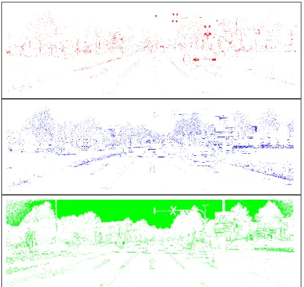
The results of the red, yellow, and green objects are shown in Figure 3. However the traffic light lenses are red, yellow, and green, these colors may be shifted in the image. For instance, the green color of the traffic light may be seen as light blue and there-fore, the thresholds in (44) are designed in a way that it includes other possible colors of the traffic lights such as light blue. The sky in Figure 3 is chosen as green object for the same reason. In addition, the boundary between red and yellow colors is ambigu-ous and the red traffic light lenses may be seen as dark yellow lenses and vice versa. Therefore, the red and yellow colors have an overlap in hue.
Figure 3: The red, yellow, and green objects are selected using threshold on the hue component of HSL color space. Yellow channel is shown in blue for better visualization.
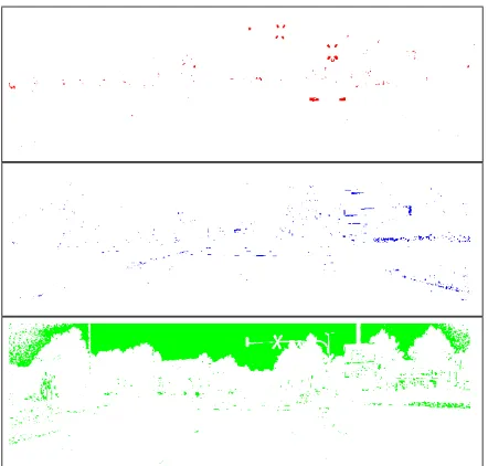
Noise in color, which is unavoidable in inexpensive cameras, can create salt and pepper noise after the color mask is applied. A median filter is used to remove these fictitious red, yellow, and green pixels. The filtered image when the median filter is applied is shown in Figure 4.
The shape cue of the traffic light lenses can also also be used. The lenses of traffic lights are circular and each circle can be seen an ellipse under perspective geometry. Therefore, objects that their are red, yellow, or green and their geometry is similar to ellipse are chosen as the possible traffic lights. For every red, yellow, and green object the boundaries of the object is extracted and the points on the boundaries are used in a least squares to estimate the best fitted ellipse (Fitzgibbon and Fisher, 1999). If an object is not ellipse shape object, the residuals of the ellipse fitting will be high and therefore, the residuals of the ellipse fitting are used to reject non-ellipse objects. Figure 5 shows the fitted ellipses to red, yellow, and green objects.
Figure 4: A median filter is applied to the red, yellow and green objects to remove noise from these objects. Yellow channel is shown in blue for better visualization.
Figure 5: An ellipse is fitted to the boundaries of the connected red, yellow, and green pixels. The objects with large residuals of the ellipse fitting are not ellipse-shape objects and should be removed.
an ellipse. These objects should be detected and removed to de-tect the traffic lights. The homography transformation in (7) can be used to transfer the red, yellow, and green ellipses in Figure 5 from the image space into the traffic light coordinate system. This back-projection is performed using homography transformation, H. Ideally,ˆCshould be equal to the conic sectionCin (6). How-ever, the back-projected ellipse will not be a circle due to noise in color image and inaccurate homography transformation. There-fore,||ˆC−C||can be used to detect the traffic lights.
In addition, the image geometry is enforced that the traffic lights must be in front of the camera and therefore,tz>0. In addition, the traffic light installation is enforced that the traffic light should be above the ground in a certain height. The traffic light position constraints are used to ensure these limitations in this paper, such that
(
3m < tu<10m
1m < tz <70m,
(45)
wheretzis the distance of the traffic light in the camera principal axis direction andtuis the traffic light height above the ground.
Figure 6 shows the traffic light lenses detected in the image us-ing mono camera. The results are not acceptable since there are other objects that are incorrectly labeled as the traffic light lenses. There are two main error sources that leads to incorrect traffic light lens detection: The color is not a robust source of infor-mation and it can change in different illumination environments and optical instruments, especially in inexpensive cameras; The shape cue may not be accurate for far traffic lights where these traffic lights have low resolution.
Figure 6: The traffic light lenses are detected using mono camera. There are many false positive traffic light lenses and this approach is not sufficiently robust approach.
3.1 using stereo to improve robustness
In the previous section, it has been shown that the traffic light lenses cannot be robustly detected using one image since there are not sufficient geometrical constraints. Therefore, the stereo cameras are used to provide redundant information and therefore, improve the accuracy of the traffic light detection. If the possible traffic lights are determined using mono camera approach for left and right images independently, the conics in two images should be matched and the pose of each possible traffic light should be estimated using a pair of conics. Let’s assume that the rotation matrix and translation vector of a traffic light in left and right images areRL,RR, tL, andtR. If these rotation matrices and translation vectors satisfy (18) and (19) in a certain level of accu-racy, the conic in left and right images are matched. These criteria allows multiple conics allocations and the wrong matches should be removed in further steps. Figure 7 illustrates the matching conics of two images. It should be noted and the red, yellow and green conics should be matched to the similar color conics.
The approach in section 2.4 can be used to estimate the pose of the conics and validate whether the object is a traffic light. In this paper, those equations are approximated using the intersec-tion approach. If the two ellipses are matched, the center of these ellipses are used to estimate three dimensional position of the traffic light. Let’s assume the center of the fitted ellipse of a traf-fic light lens in the left and right images arexL= [pxpy]⊤and xR = [qxqy]⊤.The position of the traffic light in camera co-ordinate system,X, is estimated using the disparity to distance matrix,Q, such that
ˆ
X=Qx′ (46)
wherex′ = [pxpydx1]⊤anddx=px−qx. The parallax in y direction,dy=py−qyshould be close to zero if the cameras are aligned in x direction. The disparity to distance matrix,Q, is calculated such that
andf are the principal point of the image and focal length of the camera and these parameters are calcu-lated from the calibration procedure. The distance between the principal points of two cameras is baselinebandδcx is the dif-ference of the principal points of the left and right images in x direction. When three dimensional coordinates of the object is estimated, the homography transformation in (7) can be updated such that
ˆ
H=K[r1r2X¯], (48)
whereX¯ is inhomogeneous coordinates of the object andXˆ =
[ ¯X⊤1]⊤. The homography transformation can be estimated for left image,ˆHL, and right image,ˆHR, if the information of the left camera or right camera are used. If the estimated homography transformation,ˆH, is replaced in (8), the estimated traffic light lens in traffic light coordinate system,ˆCwill be much more accu-rate than the one estimated using mono camera.
Figure 8 shows the detected traffic lights using stereo cameras. Two of the three traffic lights are correctly detected and there is no object that incorrectly labeled as the traffic light lens. The state of the traffic lights is correctly recognized and the traffic lights are correctly colored. However, one of the traffic light lenses is not correctly detected. The traffic light lens is missed because its shape is strongly distorted. The resolution of the projected traffic light is low since the traffic light is far from the camera.
4. RESULTS
The images that have been used to describe the methodology and the ones that are used in this section are chosen from the KITTI dataset. Two color 1.4 Megapixel PointGray Flea2 cameras are used to detect the traffic lights. The position of the platform ob-served by an OXTS RT 3003 integrated GPS/IMU navigation sys-tem is used to retrieve the traffic lights from GIS maps (Geiger et al., 2012, Geiger et al., 2013). The calibration procedure has been performed and the calibration parameters such as lens focal length and principal points have been estimated. In addition, the
Figure 8: The detected traffic light lenses are correctly detected and their status are correctly recognized using stereo cameras. Although, there is no false positive, there is a missed traffic light lens and it is the result of strong distortion in the shape of traffic light lens.
lever arm and boresight of the sensors have been determined with respect to the platform coordinate system (Hosseinyalamdary and Yilmaz, 2014, Hosseinyalamdary et al., 2015).
One of the KITTI scenarios has been used in section 3. to describe the implementation procedure. In addition, three more scenarios are studied in this section and the results are given in Figures 9, 10, and 11. The first row of every figure is the original image taken from the left color camera. The second row is the masked red, yellow and green objects in the left image. The median filter has been applied to remove noise in color cue, similar to Fig-ure 4. The third row is the traffic light detection algorithm using mono camera. The fourth row shows the results of the traffic light detection using stereo cameras.
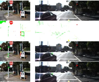
In Figure 9, the traffic light signal is green. Surprisingly, the green traffic light signal is actually light blue and the hue thresh-old in (44) should be selected in the way that the light blue is selected as possible green traffic light lens. If the threshold is extended to select the light blue, sky is most likely chosen as the possible traffic light and it should be removed in further processes such as ellipse fitting. In addition, the shade of the objects may be chosen as green object since the boundaries of the shade may be seen as light blue. In mono camera the traffic light lens is cor-rectly detected and its status is corcor-rectly recognized. However, many objects are incorrectly labeled as the traffic light lenses. In stereo camera approach, no other object is incorrectly labeled as the traffic light lens while the traffic light lens is correctly se-lected. It can be concluded that using stereo camera significantly improves the accuracy of the traffic light detection.
Figure 10 shows color of the objects can be changed due to illu-mination. In this image, sky is captured in white since it is too bright, the trees are captured in black since trees are too dark and there are shades on the street that are captured as green. Due to significant illumination changes in the image, mono camera ap-proach is not able to detect the traffic light correctly and a false positive (shade on the road) is incorrectly labeled as the traffic light. The stereo camera approach detects the traffic light cor-rectly although there is a false positive in this approach, too.
Figure 9: The traffic light detection algorithm using mono cam-era (third row) has a few false positives. The stereo camcam-eras ap-proach (fourth row) does not contain any false positive while it it maintains the true positives.
5. CONCLUSION
In this paper, the traffic light detection has been studied and two approaches, mono camera based approach and stereo cameras based approach, are proposed. The color and shape of the traffic light lens and its geometry with respect to the road and the plat-form are used to distinguish the traffic lights from other objects in the scene. The proposed approaches also investigated the use of prior knowledge in the GIS maps such as OpenStreetMaps to detect the traffic lights. The mono camera based approach is not as robust as the stereo cameras base approach and usually there are a few false positives and false negatives in this approach. It is suggested that a sequence of images are used to improve the robustness of the proposed approach in future.
REFERENCES
Caraffi, C., Cardarelli, E., Medici, P., Porta, P. P., Ghisio, G. and Monchiero, G., 2008. An algorithm for italian de-restriction signs detection. In: Intelligent Vehicles Symposium, pp. 834–840.
De Ma, S., 1993. Conics-based stereo, motion estimation, and pose determination. International Journal of Computer Vision 10(1), pp. 7–25.
Diaz-Cabrera, M., Cerri, P. and Medici, P., 2015. Robust real-time traffic light detection and distance estimation using a single camera. Expert Systems with Applications 42(8), pp. 3911–3923.
Fairfield, N. and Urmson, C., 2011. Traffic light mapping and detection. In: The International Conference on Robotics and Au-tomation (ICRA).
Fitzgibbon, A. W.and Pilu, M. and Fisher, R. B., 1999. Direct least-squares fitting of ellipses. 21(5), pp. 476–480.
Figure 10: The traffic light detection algorithm using mono cam-era (third row) can not correctly detect the traffic light and a false positive incorrectly labeled as traffic light. The stereo cameras approach (fourth row) correctly detects the traffic light although a false positive is detected too.
Geiger, A., Lenz, P. and Urtasun, R., 2012. Are we ready for autonomous driving? the kitti vision benchmark suite. In: Con-ference on Computer Vision and Pattern Recognition (CVPR).
Geiger, A., Lenz, P., Stiller, C. and Urtasun, R., 2013. Vi-sion meets robotics: The kitti dataset. International Journal of Robotics Research (IJRR).
Hosseinyalamdary, S. and Yilmaz, A., 2014. Motion vector field estimation using brightness constancy motion vector field estima-tion using brightness constancy assumpestima-tion and epipolar geome-try constraint. In: ISPRS Annals of the Photogrammegeome-try, Remote Sensing and Spatial Information Sciences, Vol. II-1.
Hosseinyalamdary, S., Balazadegan, Y. and Toth, C., 2015. Tracking 3d moving objects based on gps/imu navigation solu-tion, laser scanner point cloud and gis data. ISPRS International Journal of Geo-Information 4(3), pp. 1301.
Huang, Y.-S. and Lee, Y.-S., 2010. Detection and recognition of speed limit signs. In: International Computer Symposium (ICS), pp. 107–112.
Jang, C., Kim, C., Kim, D., Lee, M. and Sunwoo, M., 2014. Mul-tiple exposure images based traffic light recognition. In: Intelli-gent Vehicles Symposium Proceedings, 2014 IEEE, pp. 1313– 1318.
John, V., Yoneda, K., Qi, B., Liu, Z. and Mita, S., 2014. Traffic light recognition in varying illumination using deep learning and saliency map. In: 17th International Conference on Intelligent Transportation Systems (ITSC), pp. 2286–2291.
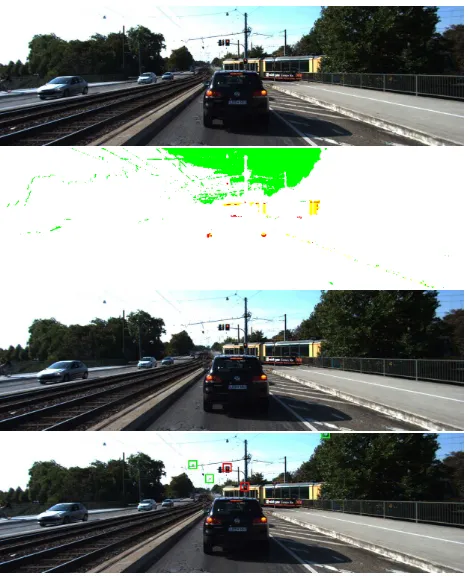
Figure 11: The traffic light detection algorithm is evaluated for a challenging scenario where the traffic light is far from the camera and their resolution is low in the images. Mono camera based ap-proach (third row) is not able to correctly detect the traffic lights are there are a few false positives. The stereo camera (fourth row) can correctly detect the traffic lights however there are few false positives.
M. J. Chantler, R. B. Fisher and E. Trucco (eds), British Machine Vision Conference (BMVC), pp. 77–86.
Levinson, J., Askeland, J., Becker, J., Dolson, J., Held, D., Kam-mel, S., Kolter, J. Z., Langer, D., Pink, O., Pratt, V., Sokolsky, M., Stanek, G., Stavens, D., Teichman, A., Werling, M. and Thrun, S., 2011a. Towards fully autonomous driving: systems and algo-rithms. In: Intelligent Vehicles Symposium (IV).
Levinson, J., Askeland, J., Dolson, J. and Thrun, S., 2011b. Traffic light mapping, localization, and state detection for au-tonomous vehicles. In: International Conference on Robotics and Automation (ICRA).
Siogkas, G., Skodras, E. and Dermatas, E., 2012. Traffic lights detection in adverse conditions using color, symmetry and spa-tiotemporal information. In: International Conference on Com-puter Vision Theory and Applications (VISAPP), Rome, Italy.