Wi
Tricity
Highly Resonant Wireless Power Transfer:
Safe, Efficient, and over Distance
Dr. Morris Kesler
WiTricity Corporation
©WiTricity Corporation, 2013 pg. 2
Highly Resonant Wireless Power Transfer:
Safe, Efficient, and over Distance
Introduction
Driving home from the airport, Marin noticed his new smart phone was low on battery once
again. Its HD display, and apps using GPS, Bluetooth, and LTE/4G data communications
conspired to drain the battery quickly. Without looking, he dropped his phone into an open
cup-holder in the center console. Hidden several centimeters below the console, a wireless
power source sensed the presence of the phone, and queried the device to determine whether
or not it was wireless power enabled. The phone gave a valid response and configured itself for
resonant wireless power transfer. Under the console, the source electronics turned on and
began charging the phone wirelessly—with no need for a charging cradle, power cord, or
especially accurate placement of the phone. Marin relaxed when he heard the recharging
chime and focused his attention on the road ahead.
After exiting the highway, Marin was surprised to see that the price of gasoline had climbed to
over $4.00 per gallon, as it had been months since he had last filled his tank of his new car-- a
wirelessly charged hybrid electric vehicle. Since installing a wireless 3.3 kW charger in his home
and office garage, his car’s traction battery was fully charged every morning before work and
every evening as he began his commute home. As Marin’s car silently pulled into his driveway,
it communicated with the wireless charger in his garage. The wall mounted charger electronics
ran through its diagnostics and sent a low-power pulse to the mat on the garage floor. Sensors
in the mat confirmed it was safe to begin charging. As Marin drove into the garage, he simply
parked his car as usual. The resonant charger had enough positioning tolerance that it would
work without needing any special parking procedures.
Marin smiled upon the realization that he no longer had to recharge or refuel two of his most
©WiTricity Corporation, 2013 pg. 3 power transfer had succeeded to make these essential products more available, convenient,
and reliable.
Although the story above is fictitious, the wireless power technology described is very real. This
article explores the advances in wireless power technology enabled by the use of highly
resonant wireless power transfer, how those advances are being applied across a broad
spectrum of applications, and how they address the safety concerns in typical applications.
Background
The idea of transmitting power through the air has been around for over a century, with Nikola
Tesla’s pioneering ideas and experiments perhaps being the most well-known early attempts to
do so [1]. He had a vision of wirelessly distributing power over large distances using the earth’s
ionosphere. Most approaches to wireless power transfer use an electromagnetic (EM) field of
some frequency as the means by which the energy is sent. At the high frequency end of the
spectrum are optical techniques that use lasers to send power via a collimated beam of light to
a remote detector where the received photons are converted to electrical energy. Efficient
transmission over large distances is possible with this approach; however, complicated pointing
and tracking mechanisms are needed to maintain proper alignment between moving
transmitters and/or receivers. In addition, objects that get between the transmitter and
receiver can block the beam, interrupting the power transmission and, depending on the power
level, possibly causing harm. At microwave frequencies, a similar approach can be used to
efficiently transmit power over large distances using the radiated EM field from appropriate
antennas [2]. However, similar caveats about safety and system complexity apply for these
radiative approaches.
It is also possible to transmit power using non-radiative fields. As an example, the operation of
a transformer can be considered a form of wireless power transfer since it uses the principle of
magnetic induction to transfer energy from a primary coil to a secondary coil without a direct
©WiTricity Corporation, 2013 pg. 4 toothbrushes, operate on this same principle. However, for these systems to operate
efficiently, the primary coil (source) and secondary coil (device) must be located in close
proximity and carefully positioned with respect to one another. From a technical point of view,
this means the magnetic coupling between the source and device coils must be large for proper
operation.
But what about going over somewhat larger distances or having more freedom in positioning
the source and device relative to each other? That’s the question that a group at the
Massachusetts Institute of Technology asked themselves. They explored many techniques for
transmitting power over “mid-range” distances and arrived at a non-radiative approach that
uses resonance to enhance the efficiency of the energy transfer (see Physics of Highly Resonant
Power Transfer for details) [3]-[6]. High quality factor resonators enable efficient energy
transfer at lower coupling rates, i.e., at greater distances and/or with more positional freedom
than is otherwise possible (and therefore, this approach is sometimes referred to as “highly
resonant” wireless energy transfer or “highly resonant” wireless power transfer (HR-WPT)). The
MIT team demonstrated the highly resonant technique using a magnetic field to transfer energy
over a mid-range distance of 2 meters, and an industry was born. In some instances, this
technology is also referred to as “magnetic resonance”, and it is often contrasted to “induction”
for its ability to efficiently transfer power over a range of distances and with positional and
orientational offsets. Since that initial demonstration, the use of HR-WPT, or magnetic
resonance, has enabled efficient wireless energy transfer in a wide range of applications that
was not possible before.
System Description
Across an application space that spans power levels from less than a watt to multiple kilowatts,
a wireless energy transfer system based on HR-WPT often has a common set of functional
©WiTricity Corporation, 2013 pg. 5
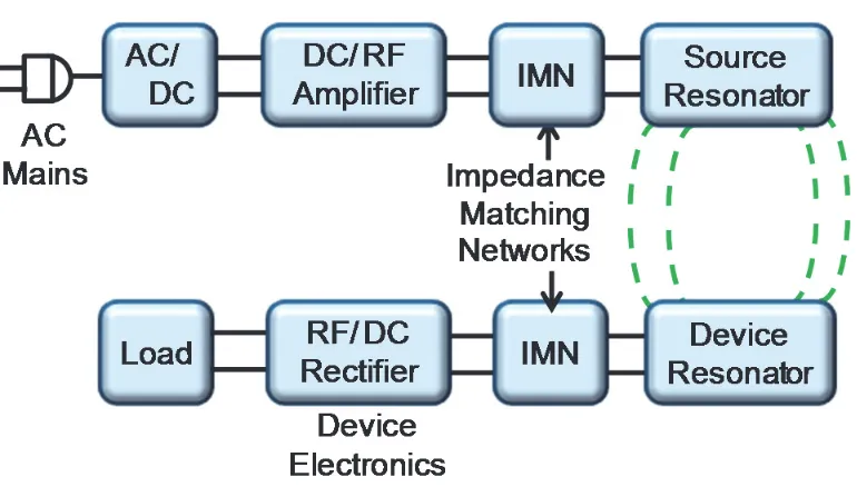
Figure 1: Block diagram of a wireless energy transfer system.
Progressing from left to right on the top line of the diagram, the input power to the system is
usually either wall power (AC mains) which is converted to DC in an AC/DC rectifier block, or
alternatively, a DC voltage directly from a battery or other DC supply. In high power
applications a power factor correction stage may also be included in this block. A high efficiency
switching amplifier converts the DC voltage into an RF voltage waveform used to drive the
source resonator. Often an impedance matching network (IMN) is used to efficiently couple the
amplifier output to the source resonator while enabling efficient switching-amplifier operation.
Class D or E switching amplifiers are suitable in many applications and generally require an
inductive load impedance for highest efficiency. The IMN serves to transform the source
resonator impedance, loaded by the coupling to the device resonator and output load, into
such an impedance for the source amplifier. The magnetic field generated by the source
resonator couples to the device resonator, exciting the resonator and causing energy to build
up in it. This energy is coupled out of the device resonator to do useful work, for example,
directly powering a load or charging a battery. A second IMN may be used here to efficiently
©WiTricity Corporation, 2013 pg. 6 an effective load impedance seen by the device resonator which more closely matches the
loading for optimum efficiency (Equation 5). For loads requiring a DC voltage, a rectifier
converts the received AC power back into DC.
In the earliest work at MIT, the impedance matching was accomplished by inductively coupling
into the source resonator and out of the device resonator [3]. This approach provides a way to
tune the input coupling, and therefore the input impedance, by adjusting the alignment
between the source input coupling coil and the source resonator, and similarly, a way to tune
the output coupling, and therefore the output impedance, by adjusting the alignment between
the device output coupling coil and the device resonator. With proper adjustment of the
coupling values, it was possible to achieve power transfer efficiencies approaching the optimum
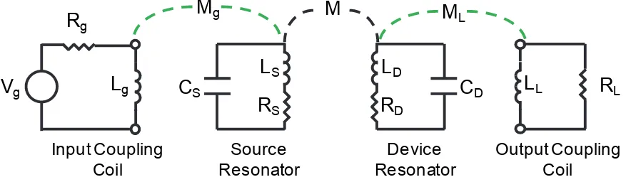
possible efficiency (Equation 6). Figure 2 shows a schematic representation of an inductive
coupling approach to impedance matching. In this circuit Mg is adjusted to properly load the source resonator with the generator’s output resistance. The device resonator is similarly
loaded by adjusting ML, the mutual coupling to the load. Series capacitors may be needed in the input and output coupling coils to improve efficiency unless the reactances of the coupling
inductors are much less than the generator and load resistances.
©WiTricity Corporation, 2013 pg. 7 It is also possible to directly connect the generator and load to the respective resonators with a
variety of IMNs. These generally comprise components (capacitors and inductors) that are
arranged in “T” and/or “pi” configurations. The values of these components may be chosen for
optimum efficiency at a particular source-to-device coupling and load condition (“fixed tuned”
impedance matching) or they may be adjustable to provide higher performance over a range of
source-to-device positions and load conditions (“tunable” impedance matching). The
requirements of the particular application will determine which approach is most appropriate
from a performance and cost perspective.
A common question about wireless charging is: How efficient is it? The end-to-end efficiency of
a wireless energy transfer system is the product of the wireless efficiency (see Physics of Highly
Resonant Power Transfer for an explanation) and the efficiency of the electronics (RF amplifier,
rectifier and any other power conversion stages, if needed). In high power applications, such as
charging of plug-in hybrid vehicles, end-to-end efficiencies (AC input to DC output) greater than
90% have been demonstrated. Such efficiencies require that each stage in the system have an
efficiency at 97-98% or greater. Careful design in each stage is required to minimize losses in
order to achieve such performance.
In mobile electronic devices, space is usually of utmost importance, so incorporating resonators
into them generally involves some tradeoffs in resonator size and system efficiency to
accommodate the space restrictions. Also, the application use-case may involve a wider range
of magnetic coupling between source and device which can also present a challenge for the
design of the impedance matching networks. However, coil-to-coil efficiencies of 90% or more
and end-to-end efficiencies over 80% are achievable in these lower power applications.
Technology Benefits and Applications
The interest in highly resonant wireless power transfer comes from many markets and
application sectors. There are several motivations for using such technology, and these often
©WiTricity Corporation, 2013 pg. 8 1. Make devices more convenient and thus more desirable to purchasers, by eliminating
the need for a power cord or battery replacement.
2. Make devices more reliable by eliminating the most failure prone component in most
electronic systems—the cords and connectors.
3. Make devices more environmentally sound by eliminating the need for disposable
batteries. Using grid power is much less expensive and more environmentally sound
than manufacturing, transporting, and using batteries based on traditional
electro-chemistries.
4. Make devices safer by eliminating the sparking hazard associated with conductive
interconnections, and by making them watertight and explosion proof by eliminating
connector headers and wires that run through roofs, walls or other barriers (even skin
tissue).
5. Reduce system cost by leveraging the ability to power multiple devices from a single
source resonator.
The high degree of scalability of power level and distance range in solutions based on highly
resonant wireless power transfer enables a very diverse array of configurations. Applications
range from very low power levels for wireless sensor and electronic devices needing less than 1
watt, to very high power levels for industrial systems and electric vehicles requiring in excess of
3 kilowatts. Furthermore, systems can be implemented for either or both a) “Wireless Direct
Powering” of a device, in which the captured energy is directly connected to a load (e.g., LED
lights) and any existing battery or energy storage component in the device is not providing
power or is providing back-up power; or b) ”Wireless Charging”, in which a battery or super
©WiTricity Corporation, 2013 pg. 9
Figure 3: Photographs of highly resonant wireless power transfer systems used to wirelessly power and operate an LCD TV (~250 W supplied wirelessly) (left) and to
wirelessly charge a battery in a smart phone (~5 W supplied wirelessly) (right).
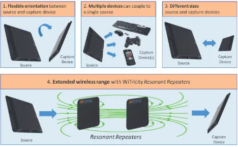
There are four (4) major functional benefits of using highly resonant wireless power transfer
systems as compared to systems based on traditional magnetic induction. The first is the
flexibility in the relative orientations of the source and device during operation. This flexibility
opens the application space as well as makes systems easier and more convenient to use.
Second, a single source can be used to transfer energy to more than one device, even when the
devices have different power requirements. For example, instead of having a separate charger
for each mobile phone in your family, you can have a charging surface that handles all of them
at once. Third, because of the ability to operate at lower magnetic coupling values, the sizes of
the source and device resonators are not constrained to be similar. Finally, the distance range
of efficient energy transfer can be extended significantly through the use of resonant repeaters
that enable energy to “hop” between them. These four functional benefits are illustrated in
©WiTricity Corporation, 2013 pg. 10
Figure 4: Schematic representation of the functional benefits of wireless energy transfer based on HR-WPT.
Wireless energy transfer systems based on HR-WPT are being developed for numerous
applications. We show examples from a few of these application areas.
Consumer Electronics
Figure 5: Photographs of a wirelessly powered laptop computer (left) and a D-Cell form-factor battery with wireless charging built in (right).
The laptop PC shown in the left photo in Figure 5 is being powered directly by a wireless power
©WiTricity Corporation, 2013 pg. 11 distance. The source and device resonators are oriented perpendicular to each other. In the
photo on the right in Figure 5, the D cell form factor battery shown charging is enabled for
wireless energy capture, and can charge at a distance of over 10 cm from the wireless charging
source. Analysts expect that the benefits of charging over distance and with spatial freedom
will result in highly resonant wireless power transfer capturing over 80% market share of all
wireless charging systems by 2020 [8].
Medical Devices
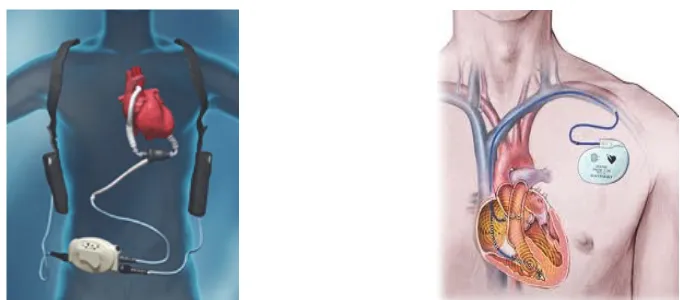
Figure 6: Pictures showing two examples of HR-WPT charging applications in medical devices: Left ventricular assist device (LVAD) (left) and pacemakers (right).
Wireless charging systems are being developed for implanted medical devices including LVAD
heart assist pumps, pacemakers, and infusion pumps. Using highly resonant wireless power
transfer, such devices can be efficiently powered through the skin and over distances much
greater than the thickness of the skin, so that power can be supplied to devices deeply
implanted within the human body. The HR-WPT technique eliminates the need for drive lines
©WiTricity Corporation, 2013 pg. 12 Electric Vehicles
Figure 7: Photograph showing an application of HR-WPT for charging full electric and hybrid vehicles.
Wireless charging systems are being developed for rechargeable hybrid and battery electric
vehicles. These systems already deliver 3.3 kW at high efficiency over a distance of 10 cm -20
cm (typical vehicle ground clearances). Figure 7 shows the Audi Urban Concept Vehicle,
demonstrated by Audi in April, 2012. It is expected that wireless charging will vastly improve
the charging experience for EV owners, making such vehicles even more attractive to
consumers.
LED Lighting
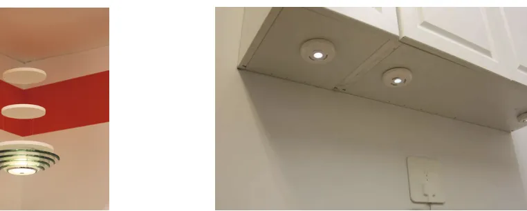
Figure 8: Photographs showing LED lights directly powered by highly resonant wireless energy transfer systems.
LED (light emitting diode) lights can be directly powered with wireless electricity, eliminating
©WiTricity Corporation, 2013 pg. 13 designers to create products that seemingly float in mid-air, with no power cord. The LED
fixture shown in the left photo in Figure 8 is powered by a 10 W source mounted above the
ceiling, and using two resonant repeaters (the white disks) to improve the efficiency of the
energy transfer.
Defense Systems
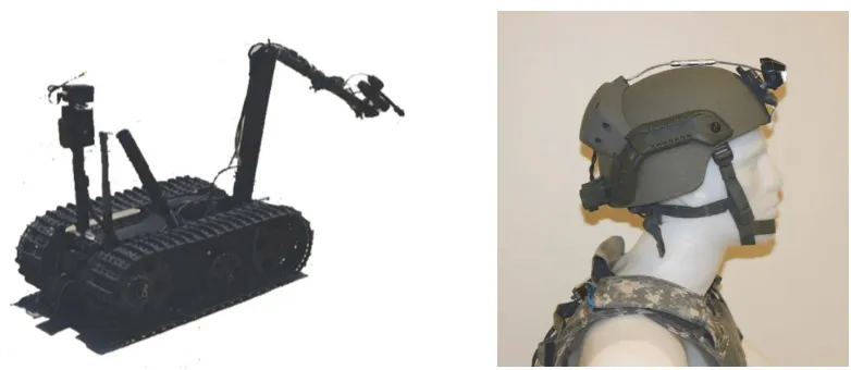
Figure 9: Photographs showing several military applications for highly resonant wireless charging systems: military robots (left) and soldier electronics (right).
Designers of defense systems are able to utilize wireless charging to improve the reliability,
ergonomics, and saftety of electronic devices. The Talon tele-operated robot shown in Figure 9
is being equipped with wireless charging so that it can be recharged while it is being
transported by truck from site to site. Helmet mounted electronics, including night vision and
radio devices can be powered wirelessly from a battery pack carried in the soldier’s vest,
eliminating the need for disposable batteries or a power cord connecting the helmet to the vest
mounted battery pack.
Over the past few years a number of standards development organizations and industrial
consortia have initiated activities to develop specifications and standards relating to the
application and commercialization of wireless power. The Society of Automotive Engineers
(SAE) has a committee developing recommendations and ultimately a standard for wireless
charging of electric and hybrid electric vehicles (cars and buses). Outside of North America,
©WiTricity Corporation, 2013 pg. 14 organizations (e.g., DKE German Commission for Electrical, Electronic & Information
Technologies and the Japanese Automobile Research Institute, among others) are doing the
same. The Consumer Electronics Association (CEA) is active in developing a standard for the
deployment of wireless power technologies in consumer applications. Also, several industry
consortia have been established to develop specifications for components and systems (e.g.,
Wireless Power Consortium (WPC), Power Matters Alliance (PMA), Alliance for Wireless Power
(A4WP)). These efforts should help speed the adoption of wireless power technology across a
©WiTricity Corporation, 2013 pg. 15
Physics of Highly Resonant Wireless Power Transfer
Resonance
Resonance is a phenomenon that occurs in nature in many different forms. In general,
resonance involves energy oscillating between two modes, a familiar example being a
mechanical pendulum in which energy oscillates between potential and kinetic forms. In a
system at resonance, it is possible to have a large build up of stored energy while having only a
weak excitation to the system. The build-up occurs if the rate of energy injection into the
system is greater than the rate of energy loss by the system.
The behavior of an isolated resonator can be described by two fundamental parameters, its
resonant frequency w0 and its intrinsic loss rate, Γ. The ratio of these two parameters defines the quality factor or Q of the resonator (Q = w0 / 2G) a measure of how well it stores energy.
An example of an electromagnetic resonator is the circuit shown in Figure 10, containing an
inductor, a capacitor and a resistor.
Figure 10: Example of a resonator.
In this circuit, energy oscillates at the resonant frequency between the inductor (energy stored
in the magnetic field) and the capacitor (energy stored in the electric field) and is dissipated in
the resistor. The resonant frequency and the quality factor for this resonator are
0
1 LC
w = (1)
L
©WiTricity Corporation, 2013 pg. 16 and
0 1 0
2
L L
Q
C R R
w w
= = =
G
(2)
The expression for Q (2) shows that decreasing the loss in the circuit, i.e., reducingR, increases the quality factor of the system.
In highly-resonant wireless power transfer systems, the system resonators must be high-Q in
order to efficiently transfer energy. High-Q electromagnetic resonators are typically made from
conductors and components with low absorptive (also sometimes referred to as ohmic,
resistive, series resistive, etc.) losses and low radiative losses, and have relatively narrow
resonant frequency widths. Also, the resonators may be designed to reduce their interactions
with extraneous objects.
Coupled Resonators
If two resonators are placed in proximity to one another such that there is coupling between
them, it becomes possible for the resonators to exchange energy. The efficiency of the energy
exchange depends on the characteristic parameters for each resonator and the energy coupling
rate, κ, between them. The dynamics of the two resonator system can be described using
coupled-mode theory [3], or from an analysis of a circuit equivalent of the coupled system of
resonators.
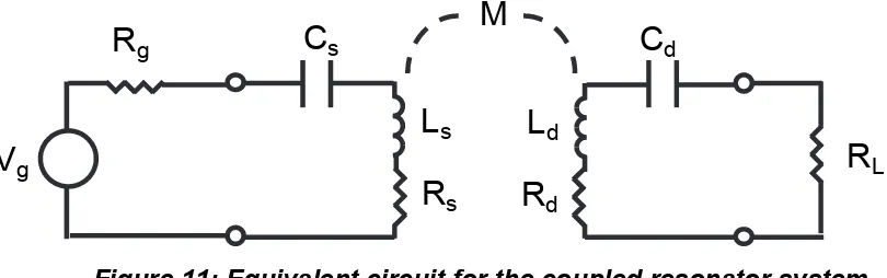
©WiTricity Corporation, 2013 pg. 17 Figure 11: Equivalent circuit for the coupled resonator system.
Here the generator is a sinusoidal voltage source with amplitude Vg at frequency w with generator resistance Rg. The source and device resonator coils are represented by the inductors Ls and Ld, which are coupled through the mutual inductance M, where
s d
M = k L L . Each coil has a series capacitor to form a resonator. The resistances Rs and Rd are the parasitic resistances (including both ohmic and radiative losses) of the coil and resonant
capacitor for the respective resonators. The load is represented by an equivalent AC resistance
L
R .
Analysis of this circuit gives the power delivered to the load resistor, divided by the maximum
power available from the source when both the source and device are resonant at w ,
2
©WiTricity Corporation, 2013 pg. 18 We have the ability to choose the generator and load resistances which give the best system
performance (or use an impedance transformation network to match to other resistance
values). If we choose
then the efficiency of the power transmission is maximized and is given by
(
)
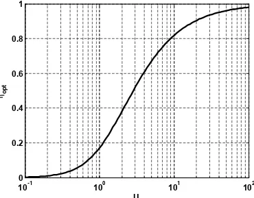
and shown in Figure 12. Here one can see that highly efficient energy transfer is possible in
systems with large values of U . Note that the impedance matching described above is
equivalent to the coupled mode theory treatment that shows that work extracted from a
device can be modeled as a circuit resistance that has the effect of contributing an additional
term, Γw, to an unloaded device object’s energy loss rate Γd, so that the overall energy loss rate
is given by
d¢ d W
G = G + G (7)
and that the efficiency of the power transmission is maximized when
©WiTricity Corporation, 2013 pg. 19 Figure 12: Optimum efficiency of energy transfer as a function of the
figure-of-merit, U.
Note that the best possible efficiency of a wireless power transmission system only depends on
the system figure-of-merit, which can also be written in terms of the magnetic coupling
coefficient between the resonators, k, and the unloaded resonator quality factors, Qsand Qd
s d
Knowing the resonator quality factors and the range of magnetic coupling between them for a
specific application, one can use Equations (6) and (9) to determine the best efficiency possible
for the system.
The wide range of applications capable of being supported by wireless power transfer systems
using HR-WPT can be estimated by examining Equations (6) and (9) that show the importance
of coupling factor and quality factor. The magnetic coupling coefficient is a dimensionless
©WiTricity Corporation, 2013 pg. 20 parameter representing the fraction of magnetic flux that is coupled between the source and
device resonators, and has a magnitude between zero (no coupling) and 1 (all flux is coupled).
Wireless power transmission systems based on traditional induction (i.e., cordless toothbrush)
typically are designed for larger values of coupling and as a result require close spacing and
precise alignment between source and device. Equations (6) and (9) show that using
high-quality resonators makes traditional induction systems even more efficient, but perhaps more
importantly, makes very efficient operation at lower coupling values possible, eliminating the
need for precise positioning between source and device and providing for a greater freedom of
movement.
Human Safety Considerations
A common question about wireless energy transfer systems using HR-WPT is: Are they safe?
Perhaps because these systems can efficiently exchange energy over mid-range distances,
people may assume that they are being exposed to large and potentially dangerous
electromagnetic fields when using these systems. Early popular press descriptions of the
technology as “electricity-in-the-air” have done little to calm people’s potential fears.
Of course, WiTricity’s technology is NOT “electricity-in-the-air”, but rather a technology that
uses oscillating magnetic fields to mediate the wireless energy exchange. With proper design
the stray electric and magnetic fields can be kept below the well-established and long-standing
human safety limits that regulate all electro-magnetic consumer devices including cell phones,
wireless routers, Bluetooth headphones, radio transmitters, etc. The high quality factor
resonators used in WiTricity systems have very low loss rates, and so can efficiently store
energy and transfer power efficiently over distance, even when the magnitude of the magnetic
fields is very low.
In this section, we will discuss what the human safety limits are, where they come from, and
©WiTricity Corporation, 2013 pg. 21 The safety limits for human exposure to electromagnetic fields are determined by on-going
reviews of scientific evidence of the impact of electromagnetic fields on human health. The
World Health Organization (WHO) is expected to release a harmonized set of human exposure
guidelines in the near future. In the meantime, most national regulations reference, and the
WHO recommends [9], the human exposure guidelines determined by the Institute of Electrical
and Electronic Engineers (IEEE) and by the International Commission on Non-Ionizing Radiation
Protection (ICNIRP).
The purposes of the IEEE [10] and ICNIRP [11] guidelines are similar:
“The main objective of this publication is to establish guidelines for limiting EMF
(electromagnetic field) exposure that will provide protection against known adverse
health effects. An adverse health effect causes a detectable impairment of the health of
the exposed individual or of his or her offspring; a biological effect on the other hand,
may or may not result in an adverse health effect”. [ICNIRP]
“The purpose of this standard is to provide exposure limits to protect against established
adverse health effects to human health induced by exposure to RF (radio frequency)
electric, magnetic, and electromagnetic fields over the frequency range of 3 kHz to 300
GHz.”[IEEE]
In their most recent reviews of the accumulated scientific literature, both the IEEE and ICNIRP
groups have concluded that there is no established evidence showing that human exposure to
radio frequency (RF) electromagnetic fields causes cancer, but that there is established
evidence showing that RF electromagnetic fields may increase a person’s body temperature or
may heat body tissues and may stimulate nerve and muscle tissues. The ICNIRP group also
concludes that the induction of retinal phosphenes1 may be considered in determining human
exposure limits. Both groups recommend limiting human exposure to electromagnetic field
1
©WiTricity Corporation, 2013 pg. 22 strengths that are well below those that cause the adverse effects described above. In the case
of tissue heating, the IEEE and ICNIRP recommend limiting the specific absorption rate or SAR, a
measure of the amount of electromagnetic energy absorbed by the human body and turned
into heat. In the case of electro-stimulation of nerve and muscle tissues and the induction of
retinal phosphenes, the groups recommend limiting the internal electric field.
The SAR and internal E-field limits are referred to as basic restrictions (BRs) because they are
“based on the physical quantity or quantities directly related to the established health
effects.”[ICNIRP]
Tissue Heating
For the case of tissue heating and/or body temperature increases, both the IEEE and ICNIRP
have determined that even the most sensitive human tissues are not adversely affected when
the whole-body averaged (WBA) SAR levels are less than 4 W/kg, corresponding to a maximum
body temperature rise of 1 °C, under normal environmental conditions. However, neither
group recommends setting the WBA SAR at 4 W/kg. Rather, both groups recommend including
a so-called “safety factor” or “reduction factor” meant as a cautionary step to compensate for
incomplete scientific data and also public perception. The IEEE and ICNIRP recommend a whole
body average SAR limit of 0.4 W/kg, for workers in controlled environments (also called
occupational exposure), and a SAR limit of 0.08 W/kg for the general public.
Note that the 0.08 W/kg limit is the whole body average or WBA SAR, and corresponds to
effects when a person’s whole body is exposed to an electromagnetic field. However, under
conditions of non-uniform or localized exposure, it is possible that the temperature of certain
areas of the body may be raised by more than 1 °C, even though the average field does not
exceed the whole body SAR limit. To accommodate these circumstances, recommendations are
also made for limiting the localized field exposure.
In general, these limits are larger because temperature rises induced by localized
©WiTricity Corporation, 2013 pg. 23 body and by cooling mechanisms associated with blood flow. Therefore, the localized SAR
values are volume-averaged and are chosen to be small enough to avoid excessive temperature
gradients over the extent of the volume but large enough to obtain an average SAR that
corresponds well to the actual temperature increase throughout the volume. The IEEE and
ICNIRP recommend a localized general public SAR limit of 4 W/kg for limbs and 2 W/kg for the
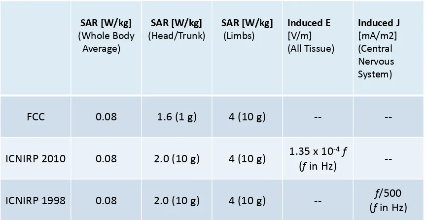
head and trunk in 10 g of tissue. We note that for the United States, the Federal
Communications Commission (FCC) has adopted a more stringent SAR limit of 1.6 W/kg
averaged over 1 g of tissue [12].
Table 1. Recommended SAR, induced electric field, and induced current (in the central nervous system) levels by ICNIRP, and the FCC regulations for those same quantities.
Nerve and Muscle Stimulation
For the case of muscle and nerve stimulation, both the IEEE and ICNIRP have identified field
levels that stimulate very minor and short-lived effects on the central nervous system, such as
the production of visual phosphenes in the eyes, which may cause a faint flickering visual
sensation, as the effect to be avoided. While both groups acknowledge that these minor
effects are not associated with any adverse health effects, they have at least temporarily
decided to set recommended field limits at very conservative values, with the intention of
refining the recommended limits as data continues to emerge.
©WiTricity Corporation, 2013 pg. 24 The general population internal electric field limits recommended by ICNIRP are similar but
slightly lower than IEEE. ICNIRP recommends an internal E-field limit of 1.35 x 10⁻⁴ *f V/m,
where f is the frequency of the electromagnetic field in Hertz. The IEEE recommends internal
E-field limits that range from 2.1 x 10⁻⁴ *f V/m to 6.3 x 10⁻⁴ *f V/m depending on which part of the
body is exposed.
Note that both the IEEE and ICNIRP acknowledge that it may be difficult to determine the basic
restrictions because they require either sophisticated measurement techniques and/or
computational capabilities, so more conservative but easier to determine reference levels
(ICNIRP) or maximum permissible exposures (IEEE) are also provided to help determine
compliance with the limits:
“Because of the difficulty in determining whether an exposure complies with the basic
restrictions (BRs), derived limits (MPEs) to protect against adverse health effects
associated with heating are provided below for convenience in exposure assessment.”
[IEEE]
“The internal electric field is difficult to assess. Therefore, of practical exposure
assessment purposes, reference levels of exposure are provided.” [ICNIRP]
Oddly enough, despite the agreement between the IEEE and ICNIRP groups on what the basic
restrictions should be, the two groups used very different estimation and scaling techniques to
develop the MPE’s/Reference Levels.
The MPE’s and Reference Levels are often referred to in the literature as the limits
recommended by the IEEE and ICNIRP, but they are not. They are simply easily measureable
electric and magnetic field levels in free space, that guarantee the BRs are met if measured field
levels are below these levels. Both the IEEE and ICNIRP guidelines are quite clear that the
©WiTricity Corporation, 2013 pg. 25 field levels exceed these MPE’s/Reference Levels may still comply with the ultimate limits, the
basic restrictions (see [10] page 24 and [11] page 495).
Electromagnetic simulations
At WiTricity, we have developed the sophisticated modeling tools necessary to assess
compliance with the basic restrictions recommended by the IEEE and ICNIRP. Our
electromagnetic simulations are performed using the finite-element method (FEM) in the
frequency domain. Although it is common to utilize finite-difference time-domain (FDTD)
methods for these types of studies [13]-[17], FEM holds several advantages and is also being
used [18]-[21]. First, in an FDTD simulation the maximum time step must be chosen to meet
the Courant-Friedrichs-Levy stability condition, which means the number of time steps required
for an FDTD simulation scales as the free space wavelength of light (1,200 m for a 250 kHz
operating frequency) over the size of the computational cell (~1 cm in the present case). The
low frequencies used for wireless power transfer would translate to very long simulation times.
As our FEM simulations are performed directly in the frequency domain rather than propagated
in the time domain, they do not suffer from this poor low-frequency scaling. Second, in a FDTD
simulation, voxel-based models of the human body must be used. In this case, the rectangular
voxel grids may not line up with the curved boundaries between different body tissues. The
actual simulations will therefore use stair-cased representations of the tissue boundaries, which
can have the effect of introducing large inaccuracies in the electromagnetic fields at these
boundaries [22]. One approach to circumvent these problems is to simply discard the upper 1%
of field values before performing the various field averages [23], but this procedure is entirely
uncontrolled and can result in significant inaccuracies. For FEM simulations, the mesh can be
forced to conform to the boundaries between different tissues, removing these stair-casing
effects.
Human body models
In order to create anatomically accurate finite-element mesh models of the human
©WiTricity Corporation, 2013 pg. 26 models obtained from MRI scan data. We then created a voxel grid from this dataset, and
generated the FEM mesh from the voxel grid. Electromagnetic properties of the various tissues
involved (muscle, bone, skin, etc.) are frequency dependent; we use values taken from studies
in the literature [25]-[27].
As one example of the simulation process using the human body models, consider the case of a
person standing next to a vehicle being wirelessly charged. Figure 7 shows a WiTricity wireless
vehicle charging system similar to that used in this simulation. The simulation was performed
with the system operating at 145 kHz and transferring 3.3 kW to the load. For this case the leg
closest to the vehicle (at approximately 65 cm from the wireless charging system) will
experience the highest fields and is the relevant portion of the human body to include in the
simulation. The car is modeled as a block of aluminum. Figure 13 shows the result of an FEM
simulation of this use case. The calculated electric field in the leg is shown on the left side of the
figure while the calculated peak SAR is shown on the right. In both cases, the values are
displayed relative to the most stringent basic restriction levels (ICNIRP for electric field and FCC
for SAR). Both measures are well below the guidelines; the largest electric field is -19 dB and
the peak SAR value is -36 dB relative to the guidelines. Thus, the highly resonant vehicle
charging system shown in Figure 7 is completely safe, as the SAR and internal E-field levels for
people standing directly against a vehicle are well below the established guideline limits. Note
that Figure 13 (right) shows the peak SAR values in the FEM simulation grid which are larger
than what would be obtained by averaging over the 1 gram volume of tissue as the FCC
regulations state. However, even these over-estimated SAR values are significantly below the
©WiTricity Corporation, 2013 pg. 27
Figure 13: Calculated electric field (left) and specific absorption rate (right) for a leg next to a vehicle being wirelessly charged at 3.3 kW. The values are normalized to the most
stringent basic restriction levels (ICNIRP electric field and FCC SAR).
A second example is a cell phone being wirelessly charged on a pad, similar to the photo in
Figure 3. In this use case, the system is operating at 6.78 MHz and the phone is receiving 5 W
from the wireless system. The geometry is a phone located on a source pad, with a hand placed
on top of the phone while charging is taking place. The fields are largest on the palm of the
hand, and the top plots in Figure 14 show the computed electric field and peak SAR values for
this portion of the hand. The bottom plots show the computed electric field and peak SAR
values for the top portion (back) of the hand. In general, as the frequency of operation is
increased, the SAR values become larger and the electric field smaller relative to the guidelines.
This is evident in Figure 14 where the largest electric field value is -20 dB relative to the
guideline, while the SAR value is closer to the guideline limit. The same use case was simulated
with a system operating at 250 kHz and the results (not shown here) are basically reversed from
©WiTricity Corporation, 2013 pg. 28 below. Note that these results show that a highly resonant cell phone charging system, such as
the one shown in Figure 3, is completely safe, as the SAR and internal E-field levels for people
holding phones while they are charging are well below the established guideline limits. As in
Figure 13, Figure 14 (right) shows the peak SAR values in the FEM simulation grid which are
larger than what would be obtained by averaging over the 1 gram volume of tissue as the FCC
regulations state. However, even these over-estimated SAR values are significantly below the
limits set by the FCC.
Figure 14: Calculated electric field (left) and specific absorption rate (right) in a hand resting on a phone being wirelessly charged at 5 W. The values are normalized to the
©WiTricity Corporation, 2013 pg. 29
The Future
With such a wide-ranging application space, we feel that the use of resonance to enhance
wireless power transfer will be prevalent in many areas of life in the coming years. Electronics
companies are already developing the necessary core components that will help speed the
introduction of the technology into more cost constrained applications. This will stimulate
additional creative ways in which to apply the technology, not only bringing convenience to
some everyday tasks such as battery charging, but also enabling uses in ways only limited by
one’s imagination.
The market for some specialty applications has already started (e.g., medical applications),
while application to automotive charging is rapidly developing and industry leaders are meeting
to discuss standardization of vehicle-charging infrastructure. For mobile electronics, a
consortium of companies has already developed a common specification for traditional
inductive charging [28]. Standards Development Organizations (SDOs) are now developing
interoperability guidelines for highly-resonant wireless power transfer to ensure that mobile
devices from different vendors can charge anywhere in a common wireless ecosystem. As these
efforts progress, expect to see wireless power technology deployed in these and many more
applications.
References
[1] Nicola Tesla, “The transmission of electrical energy without wires”, Electrical World and Engineer, March 1905. http://www.tfcbooks.com/tesla/1904-03-05.htm, (acc. Dec. 08). [2] William C. Brown, “The history of power transmission by radio waves”, Microwave
Theory and Techniques, IEEE Transactions, 32(9):1230-1242, September 1984.
[3] A.B. Kurs, A. Karalis, R. Moffatt, J.D. Joannopoulos, P.H. Fisher, and M. Soljacic, “Wireless Power Transfer via Strongly Coupled Magnetic Resonances”, Science, 317, pp. 83-86, (2007).
[4] A. Karalis, J.D. Joannopoulos, and M. Soljacic, “Efficient Wireless Non-radiative Mid-range Energy Transfer”, Ann. Phys., 323, pp. 34-48, (2008); published online April 2007. [5] J.D. Joannopoulos, A. Karalis, and M. Soljacic, “Wireless Non-Radiative Energy Transfer”,
©WiTricity Corporation, 2013 pg. 30 [6] A. Karalis, A.B. Kurs, R. Moffatt, J.D. Joannopoulos, P.H. Fisher, and M. Soljacic, “Wireless
Energy Transfer”, U.S. Patent Numbers 7,825,543 and 8,097,093.
[7] A. Karalis, R.E. Hamam, J.D. Joannopoulos, and M. Soljacic, “Wireless Energy Transfer Including Interference Enhancement”, U.S. Patent Number 8,076,801.
[8] Farouk Balouchi and Bob Gohn, “Wireless Power: Mobile Devices, Consumer Electronics, Industrial Devices, Wireless Power Infrastructure, and Wireless Charging of Electric Vehicles: Technology Analysis, Environmental Impact, and Market Forecasts,” Pike Research Report, Published 2Q 2012.
[9] World Health Organization, “Electromagnetic fields and public health”, Fact Sheet No. 304, May 2006.
[10] “IEEE Standard for Safety Levels with Respect to Human Exposure to Radio Frequency Electromagnetic Fields, 3 kHz to 300 GHz”, IEEE Std. C95.1-2005.
[11] “Guidelines for Limiting Exposure to Time-Varying Electric, Magnetic and
Electromagnetic Fields (Up to 300 GHz)”, ICNIRP Guidelines, International Commission on Non-Ionizing Radiation Protection, Health Physics, 74, no. 4, pp. 494-522, (1998). [12] Title 47 of the Code of Federal Regulations, 1.1307(b), 1.1310, 2.1091, 2.1093.
[13] “IEEE Recommended Practice for Measurements and Computations of Radio Frequency Electromagnetic Fields With Respect to Human Exposure to Such Fields, 100 kHz-300 GHz”, IEEE Std C95.3-2002.
[14] “IEEE Recommended Practice for Measurements and Computations of Radio Frequency Electromagnetic Fields With Respect to Human Exposure to Such Fields, 0-100 kHz”, IEEE Std C95.3.1-2010
[15] “Questions and Answers about Biological Effects and Potential Hazards of Radiofrequency Electromagnetic Fields”, FCC OET Bulletin 56, (1999).
[16] “Evaluating Compliance with FCC Guidelines for Human Exposure to Radiofrequency Electromagnetic Fields”, FCC OET Bulletin 65, (1997).
[17] “Evaluating Compliance with FCC Guidelines for Human Exposure to Radiofrequency Electromagnetic Fields”, FCC OET Bulletin 65—Supplement B, (1997).
[18] A. Chiba, K. Isaka, Y. Yokoi, M. Nagata, M. Kitagawa and T. Matsuo, “Application of the Finite Element Method to Analysis of Induced Current Densities Inside Human Model Exposed to 60 Hz Electric Field,” IEEE Transactions on Power Application Systems, vol. PAS-103, no.7, pp. 1895-1902, 1984.
[19] D. R. Lynch, K. D. Paulsen, J. W. Strohbehn, “Finite element solution of Maxwell’s equations for hyperthermia treatment planning,” Journal of Computational Physics, vol. 58, pp. 246-269, 1985.
©WiTricity Corporation, 2013 pg. 31 [21] Y. Yamashita and T Takahashi, “Use of the finite element method to determine
epicardial for body surface potentials under a realistic torso model,” IEEE Transactions on Biomedical Engineering, vol. BME-28, no. 9, pp. 611-621, 1984.
[22] P. Dimbylow, “Quandaries in the application of the ICNIRP low frequency basic restriction on current density,” Phys. Med. Biol., Vol. 53, pp. 133–145, 2008.
[23] T.W. Dawson, M. Potter and M. A. Stuchly, Evaluation of modeling accuracy of power frequency field interactions with the human body,” Appl. Comput. Electromag. Soc. J., vol. 16, pp. 162–72, 2001
[24] http://www.itis.ethz.ch/services/anatomical-models/static-models/
[25] C. Gabriel, S. Gabriel and E. Corthout, “The dielectric properties of biological tissues: I. Literature survey”, Phys. Med. Biol., 41, pp. 2231-2249, (1996).
[26] C. Gabriel, “Tissue equivalent material for hand phantoms”, Phys. Med. Biol., 52, pp. 4205-4210, (2007).
[27] IFAC website “An Internet Resource for the Calculation of the Dielectric Properties of Body Tissues”, http://niremf.ifac.cnr.it/tissprop/
[28] Wireless Power Consortium, Qi Specification Version 1.1,
©WiTricity Corporation, 2013 pg. 32
Morris P. Kesler, Ph.D Chief Engineer
WiTricity Corporation
Dr. Morris P. Kesler has been the Chief Engineer at WiTricity Corporation since the company began in 2007. He received his B.S., M.S. and Ph.D. degrees in Electrical Engineering and Computer Science from the Massachusetts Institute of Technology. Prior to joining Witricity, he was a founding partner of Wide Net Technologies, Inc., a high technology small business that provided research, development and engineering services to both government and industry. His work at Wide Net Technologies