DISTRIBUTED UAV-SWARM-BASED REAL-TIME GEOMATIC DATA COLLECTION
UNDER DYNAMICALLY CHANGING RESOLUTION REQUIREMENTS
Miguel Almeidaa, Hanno Hildmannband G¨urkan Solmazc
a
NEC Laboratories Europe, Kurf¨ursten-Anlage 36, D-69115 Heidelberg, Germany, [email protected] b
Universidad Carlos III de Madrid (UC3M), Av. Universidad, 30 - 28911 Legan´es - Spain, [email protected] cNEC Laboratories Europe, Kurf¨ursten-Anlage 36, D-69115 Heidelberg, Germany, [email protected]
KEY WORDS:Self-organization, adaptive behaviour, swarm algorithms, distributed sensing, autonomous decision making
ABSTRACT:
Unmanned Aerial Vehicles (UAVs) have been used for reconnaissance and surveillance missions as far back as the Vietnam War, but with the recent rapid increase in autonomy, precision and performance capabilities - and due to the massive reduction in cost and size - UAVs have become pervasive products, available and affordable for the general public. The use cases for UAVs are in the areas of disaster recovery, environmental mapping & protection and increasingly also as extended eyes and ears of civil security forces such as fire-fighters and emergency response units. In this paper we present a swarm algorithm that enables a fleet of autonomous UAVs to collectively perform sensing tasks related to environmental and rescue operations and to dynamically adapt to e.g. changing resolution requirements. We discuss the hardware used to build our own drones and the settings under which we validate the proposed approach.
1. INTRODUCTION
Autonomously operating Unmanned Aerial Vehicles (UAVs) have become a major technology in the past decade (though the U.S. military has been using UAVs for operations as far back as the Vietnam War (Broad, 1981)). Due to their low cost and high availability, airborne devices have received much interest from the private consumer, the research community, the industry and the military alike. So-calleddronesare referred to in the literature as UAVs (Schneider, 2014), UASs (Unmanned Aerial Systems) (Coopmans, 2014), RPAs (Remotely Piloted Aircrafts) (Marcus, 2014) or ROAs (Remotely Operated Aircrafts) (Ogan, 2014).
There are many ways to classify UAVs (Malone et al., 2013). Drone types and capabilities are probably as numerous as the variations on the missions where drones are involved. Some of the larger (fixed wing) UAVs can operate for hours circling over certain areas, e.g., areas contaminated by highly hazardous mate-rials (areas where a manned mission is too dangerous to human life or where providing adequate security for the human operator is simply too costly) (Malone et al., 2013), while the typical flight time of a commercial and publicly available (and affordable) off-the-shelf quadrotor is about 15 to 20 minutes (Erdelj et al., 2017). State of the art UAVs can remain airborne for prolonged periods of time (two weeks (Garber, 2014) or longer) and performance values improve significantly every year (Pauner et al., 2015).
While a lot of research was undertaken regarding the autonomous landing of UAVs in general, few studies have been directed at ma-rine environments where the challenges are more complex or cir-cumstances are more dramatic compared to land or indoor envi-ronments. Recently, quadrotor UAVs have been landed with rea-sonable accuracy on swimming objects and under outdoor condi-tions (Mendona et al., 2016). The abilities to perform complex maneuvers and to operate as large collectives of units, especially for efficient situational awareness (Erdelj et al., 2017), are going to continue to increase rapidly over the next years.
1.1 Relevant Application Areas
The United States Office of the Secretary of Defense (OSD) iden-tifies over twenty UAV mission types, ranging from intelligence, surveillance (Giyenko and Cho, 2016a), reconnaissance missions (Broad, 1981), force protection, firefighting, electronic warfare to communication nodes and others (Malone et al., 2013).
1.1.1 Civil use mission UAVs have recently been used for civil supply, inspection and various search and rescue operations (Cummings et al., 2014). For example, UAVs are used for wa-ter management and biofuel production (Coopmans, 2014) or to monitor areas for wild-life protection (Schneider, 2014). For ex-ample, the World Wildlife Fund (WWF) controls poaching and illegal wildlife trade (Goodyer, 2013) and in some of Africa’s national parks engages perpetrators of such offences (Goodyer, 2013) (though the South African Civil Aviation Authority has banned the use of UAVs in their parks (Andrews, 2014)).
1.1.2 Disaster response and relief applications UAVs can be deployed (Apvrille et al., 2014) during or after disasters to organize disaster management operations, assist the population, reduce the number of victims and mitigate the economic conse-quences (Tanzi et al., 2014). Disaster scenarios are highly dy-namic and authorities normally operate under imperfect infor-mation, which directly implies the importance of communication links (Tanzi et al., 2014), as well as the need for real-time changes in surveillance and data collection operations.
2. SWARM BASED REAL-TIME DATA COLLECTION
We address the scenarios where a number of UAVs are operat-ing as a soperat-ingle functional unit (a swarm) to provide real-time data from their individual directed sensing equipment (such as onboard cameras). In this context, individual devices provide par-tial coverage which, when combined with the data from the other devices, offers complete coverage of a target object or area.
The sensing capabilities of any equipment are bounded. Increas-ing the level of detail (e.g., the resolution of a camera) means reducing the area that is covered. If continuous coverage over an entire area is a hard constraint (as it is for certain search and res-cue missions), then this can be achieved by handing over cover-age over locations to other devices which currently operate under lower resolution requirements. However, our swarm deliversat leastthe required resolution, and“operating under lower reso-lution requirements”does not meancurrently delivering only the required minimum resolution. Due to this, handing over locations may affect the performance of the receiving device, possibly resulting in further handovers, in turn causing in the worst case -a ripple effect prop-ag-ating through the entire sw-arm.
2.1 Problem statement
The fundamental building blocks of the problem are the partici-pating devicesD(the set of drones: D={d1, . . . , dn}) andL
(all the locationsL={l1, . . . , lm}which need to be covered).
Each location li is defined by its x- and y-coordinates
(xminli ,x
li )and a resolution requirementresli.
We discretize the locations to have a width and breadth of 1 measurement unit and simplifyli = (xminli ,y
For a specific solution we distinguishLa, the set of all locations
seenat altitudea(withLa ⊆ L) as well asLdi, the set of
loca-tionsseenby dronedi(withLdi = Ladi); and finallyL ∗
di, the
set of locationsactually allocatedto dronedi, (withL∗
di ⊆ Ldi).
2.1.1 Simplifications Above we have mentionedresdi, the
resolution of dronedi’s sensor. Of course the resolution will de-pend on both the actual resolution of the sensor as well as, in case of a camera, the focal length (i.e., the resolution of the camera as well as its zoom level). In this problem we ignore any zooming capability of the cameras and pretend that this value is fixed.
We treat the surface as a flat area, i.e., we assume that the altitude of a drone correlates to the resolution provided for all locations covered by that UAV, i.e., we do not consider uneven surfaces where, e.g., locations on a hill are covered with a higher resolu-tion due to being closer to the sensor. We further simplify the definition of the covered area by assuming that for each increase in altitude the area of coverage is extended by two location, both in the width as well as in the depth of the covered area. Finally we dictate that there is a maximum altitudemax altdi a drone
dican reach and still provide coverage, if this is the same for all drones we usemax alt. The minimum,min alt, is = 0.
2.1.2 Coverage and Resolution Ldi, the set of locations seen
by dronedidepends ondi’s altitudeadiand x- and y-coordinates
(xdi,ydi) is defined as∀j, k∈ {1, . . . , adi}:
(xdi, ydi),(xdi−j, ydi),(xdi, ydi−k),(xdi−j, ydi−k)∈ Ldi.
The number of locations seen from an altitudeais given by:
|La|= (a×2)2 (1)
Therefore,|Ldi|, the number of locations that can potentially be covered by a dronedi, is determined by the UAV’s altitudeadi:
|Ldi|=|Ladi|= (adi×2)2 (2)
The resolutionrdiprovided by dronedichanges with the altitude and theintrinsic camera values. Normally we would express the resolution of an area in pixels per area and account for parameters like the focal length (zoom level) and would calculate a measure where the higher the value the better the performance. Our actual implementation includes camera resolution, a fixed focal length and the drone’s altitude, but here we provide a simplified mathe-matical model considering only the camera’s resolution.
rdi= |Ldi| resdi
(3)
We express the current resolution in terms of how much area is contained in a pixel. Minimizing this value across the entire area means to improve the number of pixels per square distance unit.
2.2 Solution and measure of success
A solution is instances of Dand Lsuch that all locations are covered and all resolution requirements are met.
2.2.1 Drone resolution To compare the quality of solutions we define an objective performance measure for the aggregated resolution provided for L∗
di (the set of locationsactually allo-catedto dronedi) by a dronediasagg resdi, calculated:
agg resd
i =rdi× |L ∗
di| (4)
2.2.2 Swarm resolution The resolution of swarm D∗ (i.e.,
the swarmDunder allocationL∗di ⊆ Ldi for all its dronesdi)
Obviously, the lowerresolutionD∗, the better the performance.
2.2.3 Resolution requirements We want to ensure that the resolution requirements are met, i.e., that for all locationslk allo-cated to a dronedithe resolutionrdiprovided by that dronediis
equal or higher thanresli:∀lk:lk∈ L∗
di →rdi ≥reslk.
2.2.4 Performance penalty If allocation L∗
di violates any
resolution requirements we define a performance penalty.
The maximum resolution requirement for droneiis:
max res(L∗di) =maxlj∈L∗di(reslj)
Ifmax res(L∗
di)can be used to calculate the maximum altitude max alt(L∗di)then the set of locations covered at this altitude is
Lmax alt(L∗
di). The set of locations which cannotbe covered at
-2.2.5 Drone penalty We definepenaltydi, the number of
in-cremental altitude changes required for dronedito meet the res-olution requirementsL∗
difor all its the locations as follows:
penaltyd i=L
-max alt(L∗
di)×(k×rdi)
withka constant used as a tuning parameter to adjust the impact of the penalty value on the behaviour of the swarm.
The rationale behind our penalty value is that we would like to hand over all locations inL
-max alt(L∗
di)to some other UAV. As
the size of this st decreases, so should the penalty.
2.2.6 Swarm penalty The penaltypenaltyD∗ of swarmD∗
can be calculated as the sum of the penalties of its members:
penaltyD∗ = ∑
di∈D∗
penaltydi (6)
2.2.7 Performance evaluation We calculate the performance
performanceD∗of a swarmD∗using equations 5 and 6:
performanceD∗ =resolutionD∗+penaltyD∗
2.3 Stochastic re-allocation of locations
The decision whether or not to re-allocate a location lk from dronedi (the current owner) to dj (a potential new owner) is stochastic, with the probability of a re-allocation being calculated using an evaluation of thecurrentstate as well as thepotential
state (i.e., the state after a re-allocation).
2.3.1 Re-allocation For a re-allocation∆of locations from one drone (di) to another (dj) we say thatL∗d∆i andL
∗∆
dj denote
the current allocation of locations andL∗∆′
di andL ∗∆′
dj denote the
new allocation, resulting from performing re-allocation∆.
Exchanges of locations happen always between exactly two drones, diand dj and on the basis of an estimate of the over-all situation before and after a (potential) exchange of locations. Such an estimate will consider the resolution provided by both drones together as well as a penalty for all locations for which the required resolution is not met.
We require that(L∗∆
set of locations covered by both drones together does not change.
2.3.2 Optimizing resolution From above we have means to calculateagg res{di,dj} for any two dronesi, jwithL
∗
di and
L∗
dj, respectively. We defineresolution before(∆) and resolu-tion after(∆)based onL∗∆
2.3.3 Penalty As above, we definepenalty bef ore(∆)and penalty af ter(∆)based onL∗d∆i,L
penalty before(∆) =penalty{d i,dj}
penalty after(∆) =penalty{d i,dj}
2.3.4 Stochastic decision The probabilityP∆of performing
re-allocation∆is calculated as follows:
P∆=
before(∆)α
(before(∆)α+after(∆)α)
with a tuning parameterαand
before(∆) = (resolution before(∆) +penalty before(∆))
after(∆) = (resolution after(∆) +penalty after(∆))
3. HARDWARE AND SIMULATION FRAMEWORK
We built and programmed our own UAVs to enable a realistic testing of the proposed approach and to be able to easily show-case the use of a swarm of drones. We furthermore developed a demonstration platform to showcase multi-device solutions / col-laboration between devices (e.g., swarms).
3.1 Drone prototype design
Our drones are quadcopters with a maximum power demand of 500W (the demand when hovering is approx. 70W), on board battery (11,1v 3000mAh), approximate weight of 600g (giving us an additional load capacity of around 300g). The projected flight time for use in demos (outside and subjected to environ-mental conditions but without additional load) is 15 minutes. The dimensions are 177mm x 177mm x 192mm (cf. Fig. 1).
3.1.1 Control module (CM) As not uncommon in the lit-erature (Mhatre et al., 2015) (Choi et al., 2016) (Giyenko and Cho, 2016b), the onboard computing platform (running the con-trol module (CM), the simulated mobile platform as well as the optional simulated sensor platform is a Raspberry Pi 2 (see Fig. 1) with the following specifications: a 900MHz quad-core ARM Cortex-A7 CPU, 1GB RAM, 4 USB ports, 40 GPIO pins, Full HDMI port, Ethernet port, combined 3.5mm audio jack and com-posite video, camera interface (CSI), display interface (DSI), Mi-cro SD card slot, VideoCore IV 3D graphics core. It is running Linux (Raspbian) as operating system and ROS (BSD or LGPLv3 or GPLv3 License) over VPN to connect to other modules.
We used MAVROS to publish the autopilot’s / SITL’s mavlink data to the network, relays it to GCS (Ground Control Software) and furthermore relays the CM’s instructions to the autopilot. The Ardupilot SITL (SW in the loop, GPLv3 License, cf., e.g,. (Bupe et al., 2015) (Rojas et al., 2015) (de Albuquerque et al., 2016) (Guevara et al., 2015) (Mukherjee et al., 2014)) autopilot soft-ware facilitates the simulation of flight operations and enables us to use additional Raspberry Pis to simulate larger swarms.
Figure 1. (top left) The pixhawk flight module / autopilot, (top right) the Raspberry Pi 2 and (bottom) one of the NEC MSP prototypes used for the evaluation and testing of the approach.
3.2 Simulation / Testing Environment
The process of designing and implementing distributed algo-rithms for the control of swarms poses the challenge of evaluating and testing them in the real world, that is, using actual hardware and letting it operate in a physical environment. UAV use and availability is spreading faster than awareness of - or legislative frameworks to address - related concerns (Pauner et al., 2015). Their rapid adoption outpaces legal, policy, and social ability to cope with issues regarding privacy and interference with well-established commercial air space (Sterbenz, 2016). Regulations differ between countries (Erdelj et al., 2017) and have to address a number of technical and societal concerns and challenges (Vat-tapparamban et al., 2016). (Altawy and Youssef, 2016) surveys the main security, privacy, and safety aspects associated with the use of civilian drones in the national airspace.
By their nature (distributed and intended for swarms), the pro-posed algorithms require a substantial number of devices in order to show the intended benefit. The device type itself poses the problem of being subjected to a variety of different legal require-ments depending on where (location) and under which circum-stances (commercial, non-commercial, etc) they are operated.
The demonstration platform currently under development will ad-dress these issues by (a) facilitating the use of large numbers of simulated devices to augment a small swarm of physical devices; and (b) enabling the co-location of physical devices that are fac-tually not in the same place. While the latter makes it possible to share resources between different labs, it is primarily aimed at enabling us to perform demonstrations in areas where the legal restrictions for the operation of physical drones would otherwise prevent the demonstration (or make it exceedingly expensive).
Figure 2. Parts of the demonstration platform: control unit, physical devices, simulated devices and a visualization module.
Figure 3. A conceptual overview over the mobile sensing platform (the hardware is shown in Figure 1).
Figure 2 shows the 4 components of the platform: (1) a control interface to run the simulation, (2) physical devices (possibly in a number of different locations), (3) simulated devices and finally (4) a visualization module showing the scenario.
We designed the platform to be able to handle a number of differ-ent devices, i.e., it is not restricted to our quadcopters or, for that matter, to drones in general. Specifically the use with fixed-wing drones as well as rovers (unmanned ground vehicles) is possible and simulations could use all of these device types together.
The current project only considers one type of drone, but planning for this functionality already sets the stage for future projects that focus on inter-swarm collaboration and enables us to evaluate the performance of our algorithms in a broader context.
The control unit as well as the visualization tool are realized in a control station (a PC or a laptop), which communicates through a wireless network with the members of the swarm (cf. Fig. 3).
We do not distinguish between virtual and physical devices or even the device type (though in the foreseeable future we will only be using quadcopters) and call all of themmobile sensing platforms(MSPs) as in Fig. 3.
Within each MSP (of which there can be many) we distinguish between (a) the computing platform where the NEC proprietary algorithms are used (this is calledcommand module(CM) and with the exception of the flight module, all elements shown are part of the CM), (b) a sensor array (real or simulated), (c) the flight module (the hardware controlling the drone) and (d) the mobile hardware platform (i.e., the drone).
3.3 Implementation
The implementations required code for two physically separate parts of the demonstration platform: the control station (contain-ing theDispatchmodule) and UAV. For either algorithm imple-mentation, theDispatchmodule was the only module on the con-trol station side for which code needed to be written (for the im-plementation of the algorithm; there was additional code written for the implementation of theSystem Controlto handle, e.g., UAV registry). On the UAV side, the only module that was concerned was theComputing Platformpart of the MSP.
The control station is a laptop (running instances ofDispatch,
EnvironmentandSystem Control) while, as discussed, the Com-puting Platformon our UAVs was a Raspberry Pi 2.
3.3.1 Control station side (Dispatch module) On the con-trol station side (in our case the laptop used to supervise the op-erations) only theDispatch module is involved because this is where all altitude control relevant interaction between UAVs and the control station is happening. That is, any communication be-tween the UAVs and the control station which is related to an on-going swarm surveillance operation happens exclusively through theDispatch, be it for general day-to-day operations as well as for dedicated and task specific operations (such as, e.g.,“providing sensor readings for location L”or, as in this case,“orchestrating UAV swarm based video surveillance for area A”).
For the altitude control algorithm we assume that the high level task of controlling the swarm is handled by a compartmentalized sub-system. Due to this we implemented a system that allows UAVs to sign on to it as participating members (having been in-structed to do so by another module sub-system of Dispatch) and which will be the interface between the application side (what-ever it may be) and the UAV swarm.
In a fully developed and deployed systemDispatchwould also handle the data streams generated by the UAVs (e.g., video streams, coming from different UAVs and, together, covering all locations in the target area). Dispatch would combine these and pass them through to either the software analyzing the data or to the output device specified by the human operator.
3.3.2 UAV / drone side (MSP control module) For the UAV implementation the choice for either a centralized or a decentral-ized approach had to be made. Since the algorithm is inherently intended to be decentralized the choice is determined by opera-tional and practical considerations: in the implementation of the simulation and demonstration platform (using ROS as communi-cation framework) we found that the communicommuni-cation overhead was large because coordinating asynchronous communications between many different devices required a lot of time.
We implemented a centralized version of the approach where the code running on the laptop is coordinating the swarm: It performs all the calculations and periodically updates the swarm accord-ingly. However, this centralized version can also be implemented to run on one of the UAVs which then performs all the calcula-tions and once a decision to re-allocate a location is made this
“master drone”simply updates the swarm accordingly.
In the de-centralized approach, all UAVs compete for locations and interactions between UAVs are always between two UAVs that can both cover a specific location. Our decision to imple-ment the algorithm in a centralized form was due to the inherent
TCP/IP and wireless latency. A message round trip will take ap-prox 20ms which would mean that demonstrations would work slower than preferred. This is an issue that can be addressed by better or different communication architectures. We don’t foresee any major obstacles when implementing the algorithm for a fleet of real UAVs. At the moment, the centralized implementation allows us to evaluate the approach without loss of generality.
3.3.3 Communication protocols The Dispatch module han-dles all issues related to communication with the swarm. UAVs sign on to a surveillance swarm and Dispatch supplies them with current and updated resolution requirements. The individ-ual UAVs in return supply the Dispatch with a series of video streams (as well as an indication which areas these relate to).
4. RESULTS AND EVALUATION
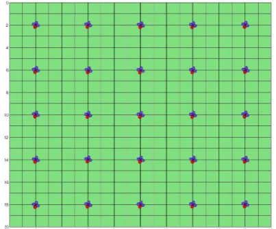
To test the approach we created a swarm of 25 UAVs and used an area of 20×20 locations. UAVs were positioned at the intersec-tion of 4 locaintersec-tions and distributed homogeneously over the area. Figure 4 shows the set up of the simulated area.
UAV altitudes were discrete: there were 11 altitudes ranging from zero (ground level) to 200m (consequently, at 10 of these 11 alti-tudes coverage over increasingly large areas is provided). UAVs started at 200 meters (the highest altitude where minimum res-olution requirements could be met) but could ascend to higher altitudes (and in the initial phase of a simulation some of them do, so as to facilitate the trading of locations with UAVs that are further away) in steps of 32.05371m - 200m. All UAVs initially started at altitude 200m and then descended to the initial location.
Whenever not used to control a real UAV, multiple instances of a simulated MSP were executed on a single Raspberry Pi. This implies that the results are, if anything, on the cautious side as we used only a fraction of the available computation power to run the individual UAVs. For an eventual implementation of the system we would use a more powerful computer at theDispatchside to improve performance even further.
When simulating the surveillance swarm we ignored zooming of cameras altogether. The reason for this is that the algorithm is effectively trading off covered area for quality of video feed, and both, the changes in altitude or the zooming cause the same changes in coverage and quality. Implementing a realistic model for both would have caused a lot of extra work without providing any benefit as far as the evaluation of the algorithm is concerned.
In a trial implementation we would improve the actual delivered quality by making use of both mechanisms: since zooming will most likely be a lot faster and a lot cheaper (energy wise), we will use zooming to cover changes quickly and then adapt the altitude of the UAVs to ensure zooming never leaves the UAV at one end of the spectrum (fully zoomed in or out).
Figure 4. The test area (400 locations arranged in a 20×20 grid) and the 25 UAVs in homogeneous swarm formation.
4.1 Baseline performance
We first establish a baseline performance for the algorithm by us-ing it to optimize the altitude of a swarm of UAVs in the absence of resolution requirements. Due to the homogenous distribution of the UAVs (cf. Fig. 4) we know that the best possible solution is when all UAVs have descended to the altitude when they can cover two fields in any direction (i.e., an area of 4×4 locations). Given that the distribution of the UAVs allows for a unique best possible solution, we can test the convergence property of the al-gorithm. And indeed, the graphs in Fig,. 6 show that the swarm converges quickly towards the best solution. The standard devi-ation shows that after a brief initial phase the UAVs do not only decrease their altitudes but do so increasingly coherent until they all arrive at, and hold, the same altitude.
This already shows that the approach does indeed perform as in-tended / predicted. In the following sections we will take a closer look at the performance of the algorithm when resolution require-ments are added and removed, i.e., for cases when the optimal solution is not as straight forward to find as in the baseline case.
4.2 Performance under dynamic requirement changes
To test the performance of the algorithm when the resolution re-quirements are not uniformly distributed / the same everywhere we added specific resolution requirements during the simulation. The following resolution requirements were added (cf. Fig. 5):
• until iteration 1999no requirements are present, all drones descend to their optimal altitude.
• at iteration 2000two resolution requirements are added for locations 6,6 and 14,14. At 3.27 mm/pixel this forces the closest UAV to descend to altitude 1 in order to meet the resolution requirements and the previously covered 4×4 locations have to be handed over to neighbouring drones.
• at iteration 4000the previous requirements are moved to locations 6,14 and 14,6 by removing them at iteration 3999 and adding the new ones at iteration 4000.
• at iteration 6000existing requirements are removed in the previous iteration and one is added for location 10,10.
• at iteration 8000the initial two requirements are repeated.
(a) (b) (c) (d)
Figure 5. Requirements: iterations 0-1999, (a) none, (b) 2000-3999, (c) 4000-5999, (d) 6000-7999 and (b) 8000-end.
4.3 Individual altitudes
In the baseline scenario all drones converged on the same altitude and into a stable formation (cf. Fig. 6). Under changing resolu-tion requirements the optimal soluresolu-tion(s) are less stable and the occasional space exploration occurs (cf. Fig. 7).
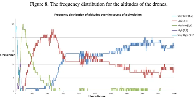
The next two graphs (cf. Figures 8 and 9) show the various alti-tudes at which drones are found throughout the surveillance sim-ulation. These represent the actual altitudes under the simplifi-cation that disallows zooming. For a full deployment we would make use of the camera zoom and then have the drones follow, in other words the actual image quality can be expected to be bet-ter (the delivery of increased resolution to be fasbet-ter and smooth) than the altitude changes plotted in the graphs. To have a closer look at the altitudes we provide the frequency distribution for the swarm’s altitudes. We can see that after the initial allocation and optimization, the vast majority of UAVs remains either on altitude 2 (the optimal altitude in the absence of any resolution require-ment) and altitude 3. Only 1 or 2 UAVs are observed at altitudes 4 and 5. These are the UAVs that have to increase their altitude to cover locations previously allocated to a UAV that is now flying closer to a location with resolution requirements.
4.4 Discussion
The benchmark scenario shows the drones continuously improv-ing on their initial performance and settlimprov-ing into the (obvious) best possible solution. When increased resolution requirements are imposed, the swarm responds through altitude changes by in-dividual drones, some to provide the required solution and some to take over the areas previously covered by the former. In our evaluation we were mainly interested in the ability of the swarm to consistently converge on good solutions and less on the re-sponse time. The motivation for this is that the rere-sponse time directly responds to the number of iterations the swarm / indi-vidual drones can perform per second, which in turn depends on the hardware available. We argue that response times can be im-proved through (a) more powerful on-board computing hardware or (b) the use of cloud based resources or a dedicated control computing facility. In addition, the actual response time required to change the altitude can be off-set through the use of zooming.
5. CONCLUSION
Figure 6. The coverage problem without requirements, baseline performance: homogeneous altitudes (best possible solution).
Figure 7. The altitudes of the UAVs in the surveillance swarm under the changing resolution requirements (cf. Fig. 5).
Figure 8. The frequency distribution for the altitudes of the drones.
ACKNOWLEDGEMENTS
The presented work was undertaken as part of a project by NEC Laboratories Europe, the approach is the subject of a pending patent application (PCT/EP 2015/062810 (pending))
REFERENCES
Altawy, R. and Youssef, A. M., 2016. Security, privacy, and safety aspects of civilian drones: A survey. ACM Trans. Cyber-Phys. Syst.1(2), pp. 7:1–7:25.
Andrews, C., 2014. UAVs in the wild. Engineering Technology
9(7), pp. 33–35.
Apvrille, L., Tanzi, T. and Dugelay, J.-L., 2014. Autonomous drones for assisting rescue services within the context of natural disasters. In:General Assembly and Scientific Symposium (URSI GASS), 2014 XXXIth URSI, pp. 1–4.
Broad, W. J., 1981. The U.S. flight from pilotless planes.Science
213(4504), pp. 188–190.
Bupe, P., Haddad, R. and Rios-Gutierrez, F., 2015. Relief and emergency communication network based on an autonomous de-centralized UAV clustering network. In: SoutheastCon 2015, pp. 1–8.
Choi, H., Geeves, M., Alsalam, B. and Gonzalez, F., 2016. Open source computer-vision based guidance system for UAVs on-board decision making. In: 2016 IEEE Aerospace Conference, pp. 1–5.
Coopmans, C., 2014. Architecture requirements for ethical, accu-rate, and resilient unmanned aerial personal remote sensing. In:
Unmanned Aircraft Systems (ICUAS), 2014 International Con-ference on, pp. 1–8.
Cummings, M., Bertucelli, L., Macbeth, J. and Surana, A., 2014. Task versus vehicle-based control paradigms in multiple unmanned vehicle supervision by a single operator. Human-Machine Systems, IEEE Transactions on44(3), pp. 353–361.
de Albuquerque, J. C., de Lucena, S. C. and Campos, C. A. V., 2016. Evaluating data communications in natural disaster sce-narios using opportunistic networks with unmanned aerial vehi-cles. In:2016 IEEE 19th International Conference on Intelligent Transportation Systems (ITSC), pp. 1452–1457.
Erdelj, M., Natalizio, E., Chowdhury, K. R. and Akyildiz, I. F., 2017. Help from the sky: Leveraging UAVs for disaster manage-ment.IEEE Pervasive Computing16(1), pp. 24–32.
Garber, L., 2014. News briefs.Computer47(6), pp. 12–17.
Giray, S., 2013. Anatomy of unmanned aerial vehicle hijacking with signal spoofing. In:Recent Advances in Space Technologies (RAST), 2013 6th International Conference on, pp. 795–800.
Giyenko, A. and Cho, Y. I., 2016a. Intelligent UAV in smart cities using iot. In: 2016 16th International Conference on Control, Automation and Systems (ICCAS), pp. 207–210.
Giyenko, A. and Cho, Y. I., 2016b. Intelligent unmanned aerial vehicle platform for smart cities. In:2016 Joint 8th International Conference on Soft Computing and Intelligent Systems (SCIS) and 17th International Symposium on Advanced Intelligent Sys-tems (ISIS), pp. 729–733.
Goodyer, J., 2013. Drone rangers [africa special sustainability].
Engineering Technology8(5), pp. 60–61.
Guevara, K., Rodriguez, M., Gallo, N., Velasco, G., Vasudeva, K. and Guvenc, I., 2015. UAV-based gsm network for public safety communications. In:SoutheastCon 2015, pp. 1–2.
Malone, P., Apgar, H., Stukes, S. and Sterk, S., 2013. Un-manned aerial vehicles unique cost estimating requirements. In:
Aerospace Conference, 2013 IEEE, pp. 1–8.
Marcus, M., 2014. Spectrum policy challenges of UAV/drones [spectrum policy and regulatory issues]. Wireless Communica-tions, IEEE21(5), pp. 8–9.
Mendona, R., Marques, M. M., Marques, F., Loureno, A., Pinto, E., Santana, P., Coito, F., Lobo, V. and Barata, J., 2016. A cooper-ative multi-robot team for the surveillance of shipwreck survivors at sea. In:OCEANS 2016 MTS/IEEE Monterey, pp. 1–6.
Mhatre, V., Chavan, S., Samuel, A., Patil, A., Chittimilla, A. and Kumar, N., 2015. Embedded video processing and data acqui-sition for unmanned aerial vehicle. In:2015 International Con-ference on Computers, Communications, and Systems (ICCCS), pp. 141–145.
Montufar, D., Munoz, F., Espinoza, E., Garcia, O. and Salazar, S., 2014. Multi-UAV testbed for aerial manipulation applications. In:
Unmanned Aircraft Systems (ICUAS), 2014 International Confer-ence on, pp. 830–835.
Mukherjee, A., Chakraborty, S., Azar, A. T., Bhattacharyay, S. K., Chatterjee, B. and Dey, N., 2014. Unmanned aerial system for post disaster identification. In: International Conference on Circuits, Communication, Control and Computing, pp. 247–252.
Ogan, R., 2014. Integration of manned and unmanned aircraft systems into U.S. airspace. In: SOUTHEASTCON 2014, IEEE, pp. 1–4.
Pauner, C., Kamara, I. and Viguri, J., 2015. Drones. current chal-lenges and standardisation solutions in the field of privacy and data protection. In: 2015 ITU Kaleidoscope: Trust in the Infor-mation Society (K-2015), pp. 1–7.
Rojas, A. J., Gonzalez, L. F., Motta, N. and Villa, T. F., 2015. Design and flight testing of an integrated solar powered UAV and wsn for remote gas sensing. In: 2015 IEEE Aerospace Confer-ence, pp. 1–10.
Schneider, D., 2014. Open season on drones? Spectrum, IEEE
51(1), pp. 32–33.
Sterbenz, J. P., 2016. Drones in the smart city and iot: Proto-cols, resilience, benefits, and risks. In: Proceedings of the 2Nd Workshop on Micro Aerial Vehicle Networks, Systems, and Ap-plications for Civilian Use, DroNet ’16, ACM, New York, NY, USA, pp. 3–3.
Tanzi, T., Apvrille, L., Dugelay, J.-L. and Roudier, Y., 2014. UAVs for humanitarian missions: Autonomy and reliability. In:Global Humanitarian Technology Conference (GHTC), 2014 IEEE, pp. 271–278.