AUTOMATED FEATURE BASED TLS DATA REGISTRATION
FOR 3D BUILDING MODELING
K. Kitamura a, N.Kochi a, S. Kaneko b a
Imaging and Measuring Laboratory, R&D Center, Topcon Corporation, 75-1, Hasunuma-cho, Itabashi-ku, 174-8580
Tokyo, Japan - (k_kitamura, n.kochi)@topcon.co.jp
b
Hokkaido University Graduate School of Information Science and Technology, Kita14, Nishi9, Kita-ku, Sapporo,
060-0814, Hokkaido, Japan
Commission V, WG V/3
KEY WORDS: TLS, Point Cloud, Segmentation, Registration, Feature Extraction
ABSTRACT:
In this paper we present a novel method for the registration of point cloud data obtained using terrestrial laser scanner (TLS). The final goal of our investigation is the automated reconstruction of CAD drawings and the 3D modeling of objects surveyed by TLS. Because objects are scanned from multiple positions, individual point cloud need to be registered to the same coordinate system. We propose in this paper an automated feature based registration procedure. Our proposed method does not require the definition of initial values or the placement of targets and is robust against noise and background elements. A feature extraction procedure is performed for each point cloud as pre-processing. The registration of the point clouds from different viewpoints is then performed by utilizing the extracted features. The feature extraction method which we had developed previously (Kitamura, 2010) is used: planes and edges are extracted from the point cloud. By utilizing these features, the amount of information to process is reduced and the efficiency of the whole registration procedure is increased. In this paper, we describe the proposed algorithm and, in order to demonstrate its effectiveness, we show the results obtained by using real data.
1. INTRODUCTION
We have developed a method for the automated reconstruction of CAD drawings and 3D modeling from point clouds obtained using terrestrial laser scanner (TLS). In this paper, we present a novel method for the registration of point clouds from multiple viewpoints, by assuming buildings as measurement objects. When TLSs are employed it is impossible to obtain from a single viewpoint a point cloud fully covering the entire object. Multiple scanning positions are therefore required to obtain the full data. Registration of the point clouds resulted from multiple scan positions has to be performed because the individual point clouds were measured in different local coordinate systems.
Currently, two different approaches for the registration procedure can be distinguished: one employs signalized targets and the other integrates automated methods, as proposed in this paper. In the first case, targets are placed directly on the object or in the measuring scene. The parameters of the rigid transformations between the different local coordinate systems are computed by measuring and pointing the corresponding targets in the different point clouds. This method is accurate and robust. Targets may however not always be placed in ideal and adequate positions depending on the object and the scene, e.g. dangerous locations. In addition, time and effort is needed for the preparation. As the number of viewpoint increases, it will be impossible to ignore the working time required for placing the targets.
In the second case, various algorithms have already been proposed for automated approaches. ICP (Iterative Closest Point) algorithm (Besl, 1992) is one of the most often employed and many variants of it have been presented (Chen, 1992; Rusinkiewicz, 2001). This method consists in the
minimization of the distance between the point clouds from different viewpoints by iterative computation. The tasks of correspondence determination and registration are solved at the same time. The ICP algorithm requires however initial values with a certain level of accuracy. A second drawback is the required beforehand removal of noise and background points when these are present in large quantity in the data. Johnson et al. (Johnson, 1999) had proposed a method which uses spin-image in order to recognize the shape and search the object within the point cloud. This method is however considered unsuitable to be used for registration procedures, because it is sensitive to noise and because of the difference of point densities between data. Thapa et al. (Thapa, 2009) had assumed buildings as objects used to perform the registration procedure. This method requires however the preliminarily introduction of semantic information.
We propose here a novel method which does not require any initial values, previous knowledge or targets. Since it is based on features, the registration procedure is performed automatically and is robust against the presence of noise and background elements. In our method, the feature extraction algorithm which we had previously developed (Kitamura, 2010) is performed for each point cloud as pre-processing. Planes and edges are extracted from the point cloud by a segmentation process. Normal vectors, centers of gravity, areas and edges are derived as information. The amount of processing is reduced and the efficiency is increased by utilizing them. Stamos et al. (Stamos, 2003) had proposed a method which uses extracted features as in our process. In this method, a bias may however occur in the accuracy assessment, because only the information of edges is used to compute the rigid transformation parameters. Yamanaka et al. (Yamanaka, 2009) had also proposed a method based on features. In this International Archives of the Photogrammetry, Remote Sensing and Spatial Information Sciences, Volume XXXIX-B5, 2012
case, three extracted planes which have common corner and floor are required. On the other hand, our method overcomes these limitations. In fact, the bias is very small because we utilize point data belonging to the extracted planes. In addition, there is no need to have common corners or floors, because the relative relation of multiple planes is investigated using the plane projection image (section 3.2).
Our method is summarized in the flowchart of Figure 1. It contains four steps shortly described in the followings. A) Segmentation of each point cloud and extraction of features: the information of extracted planes; centers of gravity, normal vectors, boundaries, etc. are obtained. B) Selection of candidates for correspondence plane pairs in point clouds of different viewpoints by using the plane information. C) Determination of correspondence planes: firstly, plane projection images are generated by projecting the other surrounding planes onto the candidate plane; secondly, the images for all candidate pairs are compared and the correspondence pair is determined as the one with the highest similarity; coarse registration is then performed on the basis of the obtained information and the coarse rigid transformation parameters are computed. D) Fine registration: determination of all the correspondence pairs by using planes translated by the coarse registration; optimization of the parameters by using the downhill simplex method, so as to minimize the error between the data of different viewpoints.
The method is presented in details in this paper: we describe the feature extraction procedure in Section 2, our novel registration method in Section 3, the experimental results in Section 4 and final conclusions in Section 5. In this work, we show only the results of the registration from two viewpoints, but it is possible to perform data from three or more viewpoints by processing them sequentially.
Figure 1. Flowchart of the proposed method. 2. SEGMENTATION
In this section we explain the segmentation algorithm applied to the data as pre-processing of the registration procedure. For this process is adopted the method which we had developed previously (Kitamura,2009). The flowchart of Figure 2 depicts the different steps. At first, a 2D image is obtained from the point cloud. Because TLS controls the direction of the emitted beam by precise vertical and horizontal angles, these two types of angles can be considered as the two axes of an image and a 2D representation (range image) of the point cloud can thus be generated. This process is performed for each viewpoint. The single range images are then segmented by the region growing
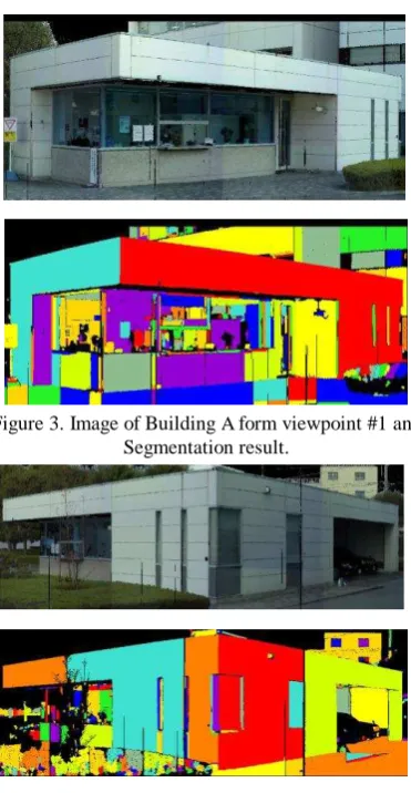
method. Normal vectors are computed for each point, as well as the distance from the point of interest to neighbors. The angle differences of the vectors and the distance between them are compared, the same label is then assigned if these values are less than predetermined thresholds. After the segmentation, edges are extracted as the intersection line of two differently labelled planes. The final result of the segmentation process consists thus of a set of extracted planes, each of them have information about its center of gravity, its normal vector, the number of points, its area and its boundaries. Figures 3 and 4 show, for two viewpoints, the Building A which is used for experiments and the results of the segmentation process, different colors represent different planes.
Figure 2. Flowchart of the Segmentation process.
Figure 3. Image of Building A form viewpoint #1 and Segmentation result.
Figure 4. Image of Building A from viewpoint #2 and Segmentation result.
Point Could of Viewpoint #1
Point Could of Viewpoint #2
Segmentation Segmentation
Select the Candidate of Correspondence plane pair
Decide the Correspondence Plane and Coarse Registration
Fine Registration
Input Point Cloud
Create Range Image
Flat Region Extraction
Region Growing
Feature Extraction
3. REGISTRATION
3.1 Selection of candidates for correspondence plane pairs A list of planes is firstly made for each point cloud by sorting all the extracted planes in accordance with their area (in decreasing order). A defined number n of planes are selected: from the first to the nth in the list. The value of n is selected depending on the object or the density of measurement, we set here n=4 for illustrative purposes. Additionally, we consider also the possibility that planes could have been divided by the effects of noise or occlusion. The coplanarity condition is used to evaluate whether different planes represent the same plane. Figure 5 depicts a situation: n1, n2 are the normal vectors of
planes S1, S2, p1, p2are points which lie on the plane and p is
the vector which is connected p1 and p2. Coplanarity indicators
are defined by the variable d, expressed as Equation (1) and by the variable a, which represents the angle between the two information is used as a form of similarity in order to evaluate pairwise the planes of different viewpoints. If the similarity order to obtain a reduced list of plane pairs with high similarity. We set the threshold Sth = 0.6(60%) and we obtain the
candidates of correspondence plane pairs: (Pa, Pe), (Pa, Pf), (Pc,
Pg).
In this paper, we have used the size of planes for the evaluation of similarity of correspondence plane pairs. However, it is possible to use other evaluation values, e.g. the convex shape, the number of corners. The goal is to get from a large number of candidates, a small number of plane pairs which have high possibility to become the correspondence pair. By reducing the number of candidates, we are able to increase the efficiency of the following procedure, which is described in the next section.
Figure 6. Selected (n=4) extracted planes in viewpoint #1 and #2.
Viewpoint #1 Viewpoint #2 Similarity (%)
Pa
Pe 90.1
Pf 81.6
Pg 10.8
Ph 3.9
Table 1. Size Similarity between Pa and plane of vewpoint #2
Viewpoint #1 Viewpoint #2 Similarity (%)
Pc
Pe 9.6
Pf 7.5
Pg 60.2
Ph 42.6
Table 2. Size Similarity between Pc and plane of vewpoint #2
3.2 Determination of correspondence planes and coarse registration
In this section, we describe the procedure that determines the single correspondence plane pairs from the reduced number of candidates which have similar sizes, obtained from the previous processing step (as described in the previous section). The evaluation of correspondences is performed by using that so called Plane Projection Images. A Plane Projection Image is created by projecting the shape of all other planes on the infinite plane containing the plane of interest. The pixel values of the Plane Projection Image are obtained by computing the distance between the projected planes and the plane of interest. The plane of interest consists in our case of the candidate of correspondence planes. Plane Projection Images are generated for each candidate for each viewpoint. Figure 7 describes how to create Plane Projection Images when the plane of interest is Pa: the infinite plane containing Pa is defined by using its
The image center is set to the center of gravity of the plane of interest. Only planes with a distance within a determined range are projected, in our case five meters or less. In the case when a plane is perpendicular against the plane of interest, only the shortest distance between them is considered; as in Figure 7, where the plane Pa is perpendicular against the plane Pb.
Figure 7. Creating Plane Projection Image
Figure 8 shows the Plane Projection Image when Pa,
respectively Pb of viewpoint #1 are set as plane of interest, and
Figure 9 shows the image for the planes Pe, Pf, and Pg of
viewpoint #2. Note the pixel values in the images becoming brighter when the recorded distance is shorter.
Figure 8. Plane Projection Image of viewpoint #1 Left: When the plane of interest is Pa, Right: Pc
Figure 9. Plane Projection Image of viewpoint #2, Top Left: When the plane of interest is Pe, Top Right: Pg,Bottom: Pf
The generated Plane Projection Images are used in order to evaluate the candidate correspondence plane pairs determined in the previous processing step. The correspondent Plane Projection Images of the candidates are compared by computing the difference of the recorded distance in each pixel by raster scan. As evaluation value, we consider RMSE of the difference of distance computed in all the pixels of the image. This evaluation value is small if the candidate plane pairs lie on the same plane. This value is computed for all the candidate pairs and the correspondence plane pair is therefore
determined as the one having the smallest. Table.3 shows RMES of some candidate plane pairs. The correspondence pair results here to be the planes Pa (viewpoint #1) and Pe
(viewpoint #2), as they have the smallest RMSE value.
Viewpoint #1 Viewpoint #2 RMSE
Pa Pe 0.348
Pa Pf 2.129
Pc Pg 1.123
Table. 3, RMSE of candidate plane pairs
The coarse registration of the two point clouds can then be performed. The two correspondence planes of viewpoint #1 and viewpoint #2 are considered and the rigid transformation between them is determined in order to match the direction of the normal vectors and the position of the centers of gravity. The transformation is expressed as Equation (3), where Rcis
the rotation matrix, Tcis the shift matrix, P2 is point cloud of
viewpoint #2 before the transformation and P2' is after the
transformation. This transformation is performed in all points of viewpoint #2.
c
c P T
R
P2
2
(3) 3.3 Fine registrationIn the previous step, the rigid transformation parameters were computed coarsely by using the information of only a single correspondence pair. In the next step of the process, the transformation parameters are revised by using all the rest of planes in order to increase the accuracy of registration. Firstly, the relation of correspondence for all the rest of planes is determined in addition to the correspondence pair found in the previous processing step. The new parameters of all the planes are directly computed according to the transformation by Equation (3). The relation of correspondence between planes is then decided by meeting both of the following two conditions: lying on the same plane and having enough overlapping area. The first condition is based on the coplanarity as described in section 3.1. For the latter, the rate of the overlapping is used; considering effects of occlusion and noise, we set its threshold at 75%.
In the second step, the rigid transformation parameters are refined by using the newly determined plane pairs and by considering the error of distance between the correspondence planes. All the planes are transformed by the coarse parameters determined before (previous section) and the distance errors for all plane pairs are computed as shown in Figure 10 by using the points from viewpoint #2 and the planes from viewpoint #1. With p2' is the transformed point cloud which
belong to viewpoint #2, p1 is the point of intersection of the
correspondence plane S1 and the normal vector n2' of plane S2,
then the distance l is expressed as Equation (4).
Figure 10. Distance between planes International Archives of the Photogrammetry, Remote Sensing and Spatial Information Sciences, Volume XXXIX-B5, 2012
2 defined as their summation. In order to minimize the error, we adopt the downhill simplex method which is a technique for minimizing an objective function in multi-dimensional spaces. This method is not fast, but it has the advantage of not requiring derivatives. The coefficients of reflection, expansion and contraction for the computation of simplex are respectively 1.0, 0.5 and 2.0. Equation (5) depicts the error e as the summation of all the distance errors in function of the rotation and shift matrices (R, T).
(R, T) are computed and updated in an iterative process. Their value is set to (Rl, Tl) when e is minimum and (Rh, Th) when e
is maximum. For the convergence test, the evaluation value c is computed according to Equation (6) using the error function e.
The assumption that c has converged is made when its value is smaller than the predefined threshold cth and at that point, the
iterative computation is halted. In our experiment, we set cth =
1.0x10⁻¹². If the iterative computation does not converge, we set
a value of 5000 for the limit of iteration number. 4. EXPERIMENT
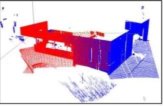
We used a Topcon GLS-1500 terrestrial laser scanner for our registration experiment. The experiment was conducted by measuring different objects without placing targets on them or in the scene. The required processing time listed in this paper were obtained by using a PC with Intel Core2Duo P8700 2.53GHz and 2.8GB RAM. Three different kinds of buildings represented our sample data: building A (shown also in previous figures), B and C. Figures 10, 11 and 12 show the results obtained by the proposed registration method. The point clouds of viewpoint #1 and viewpoint #2 are represented respectively in red and blue.
Table 4 shows the number of point and the number of extracted planes for each viewpoint, the processing time (including segmentation processing time) and the mean error of distance between correspondence planes.
Figure 10. Registration result for Building A.
Figure 11. Images of Building B and registration result.
Figure 12. Images of Building C and registration result. Sample
Table 4. Evaluation of the results. Number of points [x104] and
extracted planes, processing time [sec], mean error of distance between correspondence planes [mm].
The processing time for building B whose point cloud has seven million points for each viewpoint was about six minutes. Few hours working time would be required if we would adopt methods based on ICP algorithm. In fact, manual editing of the original point clouds would be required in order to remove non-common parts and in order to perform the pre-registration with a certain level of accuracy as the pre-processing. On the contrary, our proposed method does not require this pre-processing and performs the entire process in practical time. Moreover, building C features a lot of non-common parts such as vegetation in its surrounding. Despite this situation, the proposed method performs successfully also without removing these parts. correspondence planes was computed for the evaluation of the accuracy of the methods. The mean absolute error was 6.38mm by using the signalized targets and 7.28mm by using our International Archives of the Photogrammetry, Remote Sensing and Spatial Information Sciences, Volume XXXIX-B5, 2012
proposed method. These results confirm that both methods have similar levels of accuracy.
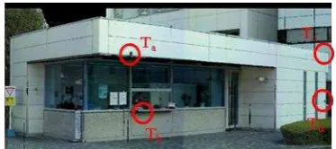
Some interesting considerations with respect to placing signalized targets can be drawn from the practical experiences we gained by the experiment. We had to use a step ladder in order to place targets Ta and Tc because they were located over
two meters high; the other targets could be placed easily. This was the only preparation required by this experiment. However, depending on the object to be measured and the surrounding scene, the placement of the targets in the wished locations may result dangerous and eventually also not possible. Our proposed method, allowing automated registration without targets, can therefore bring additional advantages as ensuring the safety of workers and reducing time and effort for the preparation and work.
Figure 13. Location of the four signalized targets used to verify the accuracy of the proposed method.
5. CONCLUSIONS
We have developed a novel automated method for the effective registration of point clouds from multiple viewpoints without the need of targets, by using the information of extracted planes obtained by segmentation. In comparison with methods employing targets, our proposed method allows, not only to omit the work and time for placing targets, but also to ensure the safety of workers. The measurement of an object by using our automated method is possible even if the operators have no experience or skills for placing targets. Moreover, an accuracy evaluation experiment, conducted by using the mean absolute error of distance between correspondence planes, confirmed that our method has a similar level of accuracy as method employing targets. By using our method it is possible to process point clouds in a more effective way than treating them directly. Additionally, it is not required to perform time expensive pre-processing procedures as the removal of noise or background elements from the point clouds and the subsequent pre-registration with initial values. For this reason, our method allows to perform the whole process in practical time. We have tested the proposed registration procedure with other nine sample data, in addition to three experiments described in this paper, and we have obtained results with similar accuracy. We believe that we will be able to generate automatically 3D building models and CAD drawings from point clouds of multiple viewpoints, by using the segmentation and registration procedures which we have developed and described in this paper. We were able to demonstrate in this paper that our proposed method allows to perform the registration process more efficiently than traditional methods based on targets.
REFERENCES
Besl, P. J. and McKay, N. D., 1992. A Method for Registration of 3-D Shapes, IEEE Transaction on Pattern Analysis and Machine Intelligence, vol.14, no.2, pp.239-256.
Chen, Y. and Medioni, G., 1992. Object Modeling by Registration of Multiple Range Images, Image and Vision Computing, vol.10, no.3, pp.145-155.
Johnson, A. E. and Hebert, M., 1999. Using Spin Images for Efficient Object Recognition in Cluttered 3d Scene, IEEE Transaction on Pattern Analysis and Machine Intelligence, vol.21, no.5, pp.433-449.
Kitamura, K., D'Apuzzo, N., Kochi, N., and Kaneko, S., 2010. Automated Extraction of Break Lines in TLS Data of Real Environment. ISPRS, Vol. XXXVIII, Part 5, Com V, pp.331-336
Press, W. H., Teukolsky, S. A., Vetterling, W. T. and Flannery, B. P., 1993. Numerical Recipe in C. The Art of Scientific Computing, CAMBRIDGE UNIV PRESS (Japanese Edition). Rusinkiewicz, S. and Levoy, M. 2001. Efficient Variant of the ICP Algorithm, Proceedings of the 3rd International Conference on 3-D Digital Imaging and Modeling, pp.145-152. Stamos, I. and Leordeanu, M., 2003. Automated Feature-Based Range Registration of Urban Scenes of Large Scale, IEEE International Conference of Computer Vision and Pattern Recognition, vol.2, pp.555-561.
Thapa, A., Pu, S. and Gerke, M., 2009. Semantic Feature Based Registration of Terrestrial Point Clouds, ISPRS Workshop Laserscanning'09, pp230-235.
Yamanaka, Y. and Masuda, H., 2009. Registration of Large-Scale Point-Clouds using Planar Surface Extraction, Journal of Japan Society of Precision Engineering, ICPE 2009 autumn, M13. (In Japanese).