Active Layer
Study on a Narrow Linewidth
DFB LD and LD
-
Based Injection Locking Circuit
Claudia Khansa’ Atikah Hidayat
Department of Electrical Engineering Faculty of Engineering
Universitas Indonesia Depok, Indonesia
Abstract We demonstrate linewidth narrowing of a distributed feedback (DFB) LD and low phase noise optical carrier-phase synchronization circuit. By employing an external cavity mirror, the LD linewidth was successfully reduced from 1 MHz to 4 kHz. With injection locking, we obtained an IF signal with a phase noise as low as 0.25 degrees.
Keywords coherent transmission, injection locking, laser diode.
I. INTRODUCTION
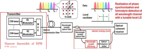
A narrow linewidth laser and precise carrier-phase synchronization scheme play a very important role in a multi-level coherent optical transmission. However, conventional commercial laser diode (LD) inherently has broad linewidth such as 100 kHz. With such lasers, it is difficult to achieve precise carrier-phase synchronization between the data signal and a local oscillator (LO) in such coherent transmission. Therefore, it is also hard to increase a data multiplicity. However, our work is aimed to obtain the narrow the linewidth of DFB LD by putting reflective partially mirror as an external cavity. We will put it in transmitter as illustrated in figure 1. Next, we implement it on the injection locking configuration by realize the precise phase synchronization.
Figure 1 below shows the fundamental configuration of coherent optical transmission system. The light at the various frequencies is being modulated in multi-level modulation format such as 16 QAM. Injection locking circuit is cooperated in order to derive the phase synchronization to be used at the local oscillator.
Figure 1 Coherent WDM optical transmissions
In this report, we demonstrate linewidth reduction of a conventional DFB LD. With an external cavity configuration, the linewidth of the LD was successfully reduced to 4 kHz. By applying this narrow linewidth LD as a master laser to an LD-based injection locking circuit,
we obtained a low phase IF (intermediate frequency) signal with a low phase noise of 0.25 degrees.
II. LINEWIDTH NAROWING OF DFB-LD
A. Principle of DFB LD array
In order to obatain a laser with the single mode oscillation, there is a need in decreasing selectively only cavity loss of a single longitudinal mode.Hence, a very strong structure of the mode selectivity, such as a diffraction grating in the resonator is required.Therefore, a laser having such a structure is referred to as a distributed feedback laser (DFB).
In DFB laser, the Bragg grating (which in this case forms also the cavity of the laser) has a phase-shift centered in the reflection band is related to a single very narrow transmission notch of a Fabry–Pérot interferometer. When configured properly, these lasers operate on a single longitudinal mode with coherence lengths in excess of tens of kilometres, essentially limited by the temporal noise induced by the self-heterodyne coherence detection technique used to measure the coherence. These DFB lasers are often used in sensing applications where extreme narrow line width is required.However theDFBlaser is also called a λ/4 shift DFB laser.
DFB lasers are those which operate at a wavelength that is not reflected by the diffraction grating both ends, shows in figure 2 Furthermore, it has a diffraction grating in the active layer, and a laser operating in two modes.
The laser which constitute a resonator in the grating in the Bragg wavelength is obtained by adding a phase shift in the distribution of the diffraction grating. Thereby, the DFB laser operates at a single Bragg wavelength.
Figure 2 Principle of DFB Laser
B. Configuration of DFB LD array
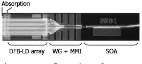
The structure of a conventional InP-based distributed feedback (DFB) laser is shown schematically in Fig. 3. The structural characteristics are as follows. It consists of 12-λͅ/4 shifted DFB LDs made of indium gallium arsenide phosphide (InGaAsP) multiple quantum well (MQW)
活性領域
DFB
帰還する
活性領域
DFB
帰還する
Narrow linewidth of DFB LD array
2015 International Conference on Automation, Cognitive Science, Optics, Micro Electro-Mechanical System, and Information Technology (ICACOMIT), Bandung, Indonesia, October 29–30, 2015
structure, the resonator length is 900 micro meters.
Figure 3 Configuration of DFB LD
Spectral line width of the DFB LD that is shown in figure 3 (a), is represented by the expression of Schawlow-Townes equation, the following relationship is derived approximately in equation (1). The longer the � , the
linewidth will be narrower because the laser resonator length is inversly proportional to the spectral linewidth of DFB LD[3].
ν ∝ � � − � − 1 + � (1)
� � : coupling coefficient of the diffraction
grating
� : laser resonator length � : linewidth enhancement factor
TLA is having a structure of other optical elements that are integrated as an external cavity. Feedback of the light from the external cavity to the LD will affects the line width characteristics as derived in equation (2) and (3).
Δ�
ν = + in ωτ+��+ an− � (2) ... (2)
And C is defined as
C = √����∙ �������������� √ �√1 + � (3)
�� : feedback coefficient
ω : laser oscillation angular frequency τ : round-trip time
�� : phase term which is determined by the DFB laser structure
� � : light output in the DFB laser front
end
��� : the average light output of the laser
resonator
��� : external waveguide length � : axial direction Petermann factor
Α : linewidth enhancement factor
From the equation (2), feedback coefficient (C) is decreased by a longer cavity length of the DFB laser
� . Thus, it will obtain a stable oscillation state
variations in the line width that can be suppressed.
The basic configuration of DFB LD is consisting of various instrument drivers act as a current booster for semiconductor optical amplifier (SOA) and LD, also the current controller. The composition of the DFB before the light output is carried out can be observed in figure 4. DFB LD is consisting of 12 LDs array. In this research, we put a work in measuring the characteristics and reducing a linewidth of LD number 6 which operates at wavelength 1548 nm.
Figure 4 Structure of tunable DFB laser array (TLA)
The DFB LD can be tuned by changing the temperature. As stated before, we picked LD 6 which operates at around 25 degree celcius and obtain the wavelenght 1548 nm. Furthermore, the output power can be varied by changing the current through the Semiconductor Optical Amplifier (SOA). It can be observed through the figure 5. (b).
(a) (b)
Fig 3.6 Fundamental characteristics of DFB LD 6. Wavelength tuning characteristics (a) and output power
characteristics (b).
Figure 6 Linewidth characteristics of DFB LD array.
C. Spectral Narrowing by Employing External
cavity
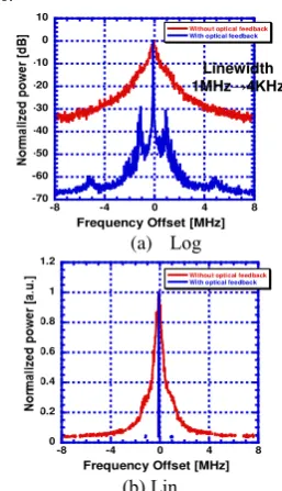
We narrowed linewidth of a conventional DFB LD array by incorporating an external cavity mirror. Figure 7 shows its configuration. The DFB LD array consists of 12 DFB-LDs, which emitted at different wavelength each other, MMI (Multimode interferometer) coupler and a semiconductor optical amplifier (SOA). A partially reflecting mirror is placed between the tunable semiconductor DFB array laser and an isolator. Among 12 LDs, we selected one LD which emits at 1549 nm and applied for spectral narrowing experiment. Figure 8(a) and (b) show the delayed self-heterodyne spectra with log and linear scale when the injection current for LD and SOA were 250 and 140 mA. These graphs also show the spectra without the external mirror. The linewidth of the LD was successfully narrowed from 1 MHz to 4 kHz.
Fig 7. Experimental setup for spectral narrowing of LD with an
external mirror.
(a) Log
(b) Lin
Fig.8 Delayed self-heterodyne spectrum.
Precise measurement of the linewidth from configuration of DFB LD on figure 7 is illustrated in figure 9. The minimum linewidth is 4 KHz at the 140 mA current and at the 2.25 mW power. However at the current more than 140 mA and power more than 2.25 mW, the linewidth gets broader. For that reason, we stopped our measurement on 140 mA current.
(a) (b)
SOA injection current versus linewidth Optical power versus linewidth
Figure 9 Linewidth of tunable DFB LD
III. INJECTION LOCKING CIRCUIT
In order for LDs to be used as LO for coherent detection, precise phase synchronization is necessary. We carried out an experiment on phase synchronization of DFB LD using an injection locking scheme.
Figure 10 shows the configuration of injection locking experiment. DFB LDs are used both for master and slave laser. We prepared a DFB LD whose output’s linewidth walocal oscillator without external mirror cavity. The output from the master laser was fed into the slave laser via an optical circulator. In doing so the optical frequency of the slave laser was drawn an synchronized to the optical frequency of the master laser as shown here. An optical signal from master laser is being injected through the optical circulator by varying the output power controlled by optical attenuator. The output from the injection-locked if slave laser was frequency-shifted using an acousto-optic modulator (AOM) and heterodyne
detected with the output from the master laser.
Fig.10. Configuration of injection locking circuit. . Figures 11(a) shows the SSB phase noise characteristics of IF signal. With an injection power of 7 dBm, we obtained a lowest phase noise of 0.25 degrees. Figure 11(b) shows the IF spectrum under this condition. The corresponding SSB phase noise spectrum is shown in Fig. 11(c).
(a)
(b)
(c)
Fig.4. Injection locking characteristics. Phase noise versus injection power (a), IF spectrum (b), and SSB phase noise(c).
IV. CONCLUSION
We successfully narrowed a linewidth of DFB
-LD from 1 MHz to 4 kHz. By using this -LD as a master LD, an LD-based injection locking circuit was
demonstrated, where a low phase noise IF signal was obtained with a phase noise as low 0.25 degrees.
References
[1] Keisuke Kasai, Akihito Suzuki, Masato Yoshida, and Masataka Nakazawa, “Performance improvement of an acetylene (C2H2) frequency-stabilized fiber laser,” IEICE Electron. Exp., vol. 3, no. 22, pp. 487-492, (2006. 11).
[2] Shohei Beppu, Keisuke Kasai, Masato Yoshida, and Masataka Nakazawa, “2048 QAM (66Gbit/s) single
carrier coherent optical transmission over 150 km with a potential SE of 15.3 bit/s/Hz,” Opt. Exp., vol. 23, no. 4, pp.4960-4969, (2015. 2).
[3] H. Ishii, Y. Tohmori, F. Kano, Y. Yoshikuni, and Y. Kondo, “Multiple-phase-shift super structure grating DBR Lasers,” IEICE Trans. Electron, vol. E76-C, pp. 1683-1690, November 1993.
[4] H. Kogelnik, and C. V. Shank, “Coupled-wave theory of distributed feed-back lasers,” J. Appl. Phys., vol. 43, no. 5, pp. 2327-2335, 1972.
[5] A. L. Schawlow and C. H. Townes, “Infrared and optical masers”, Phys. Rev. 112 (6), 1940 (1958). [6] H. L. Stover and W. H. Steier, “Locking of laser
oscillators by light injection,” Appl. Phys. Lett. 8(4), 91–93. (1966).
[7] C. J. Buczek, R. J. Freiberg, and M. M. Skolnik, “Laser injection locking,” Proc. IEEE, 61, 1411 (1973).
[8] A. C. Bordonalli, C. Walton, and A. J. Seeds, “High -performance phase locking of wide linewidth semiconductor lasers by combined use of optical injection locking and optical phase-locked loop,” J. Lighrwave technol., vol. 17, no. 2, pp. 328-342, Feb. 1999.