SYSTEM DESIGN, CALIBRATION AND PERFORMANCE ANALYSIS OF A NOVEL
360° STEREO PANORAMIC MOBILE MAPPING SYSTEM
S. Blaser a, S. Nebiker a, S. Cavegn a, b
a Institute of Geomatics Engineering, FHNW University of Applied Sciences and Arts Northwestern Switzerland,
Muttenz, Switzerland - (stefan.blaser, stephan.nebiker, stefan.cavegn)@fhnw.ch b Institute for Photogrammetry, University of Stuttgart, Germany
Commission I, WG I/9
KEY WORDS: Fisheye Stereo, Panorama, Mobile Mapping, Calibration, Epipolar Rectification, 3D City Model
ABSTRACT:
Image-based mobile mapping systems enable the efficient acquisition of georeferenced image sequences, which can later be exploited in cloud-based 3D geoinformation services. In order to provide a 360° coverage with accurate 3D measuring capabilities, we present a novel 360° stereo panoramic camera configuration. By using two 360° panorama cameras tilted forward and backward in combination with conventional forward and backward looking stereo camera systems, we achieve a full 360° multi-stereo coverage. We furthermore developed a fully operational new mobile mapping system based on our proposed approach, which fulfils our high accuracy requirements. We successfully implemented a rigorous sensor and system calibration procedure, which allows calibrating all stereo systems with a superior accuracy compared to that of previous work. Our study delivered absolute 3D point accuracies in the range of 4 to 6 cm and relative accuracies of 3D distances in the range of 1 to 3 cm. These results were achieved in a challenging urban area. Furthermore, we automatically reconstructed a 3D city model of our study area by employing all captured and georeferenced mobile mapping imagery. The result is a very high detailed and almost complete 3D city model of the street environment.
1. INTRODUCTION
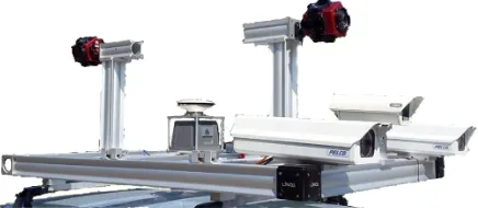
In recent years, image-based mobile mapping has evolved into a highly efficient and accurate mapping technology as it enables capturing an enormous amount of metric image data in a short time period with no or just minimal road traffic interference. First experiments with stereovision-based mobile mapping date back some 20 years, such as the GPSVan (Novak, 1991) or the VISAT system (Schwarz et al., 1993). Recent progress in positioning and imaging sensors, on-board data storage, algorithms and computing technologies such as high-performance computing have enabled very powerful stereovision mobile mapping approaches. Investigations in mobile mapping at the Institute of Geomatics Engineering (IVGI), University of Applied Sciences and Arts Northwestern Switzerland (FHNW) started in 2009 with the development of an image-based mobile mapping system (MMS) which has evolved into a multi-stereo camera system (Burkhard et al., 2012). This system generation is extensively used for large-scale road and rail infrastructure management. Extending the multi-stereo configuration to a full 360° 3D coverage for future street-level imaging services in urban areas with high buildings and numerous superstructures proved to be inefficient and triggered new investigations. Existing 360° stereo panoramic mobile mapping systems such as Heuvel et al. (2006) or Earthmine (2014) did either not fulfil the accuracy requirements or stood in conflict with national privacy laws, which, e.g. in Switzerland, prohibit street-level image acquisition from higher than 2 m above ground. In the following, we introduce a novel 360° stereo panoramic camera configuration, which uses two multi-head 360° panorama cameras, tilted forward and backward by 90° respectively (see Figure 1). This offers large, rigid stereo bases for all viewing directions while permitting image acquisition at heights compliant with strict privacy laws.
Figure 1. System overview demonstrating our novel stereo panorama camera setup
The goals of the following investigations were:
- to design a 360° stereo system for a mobile mapping system suitable for highly-accurate measurement and infrastructure management tasks
- to mechanically and electronically integrate 15+ imaging sensors with different camera models
- to develop a suitable and accurate calibration procedure for a multi-head mobile mapping system integrating both pinhole and fisheye sensors
- to design and implement a processing workflow for image-based and integrated georeferencing as well as for the efficient and accurate depth map extraction from fisheye stereo - and last but not least to evaluate the empirical accuracy of the
system with the goal of obtaining 3D measuring accuracies equivalent to those achieved with conventional pinhole stereo systems by Burkhard et al. (2012).
introduction of our study area, a quality assessment of the processed data is provided in section 5.
2. RELATED WORK
The first 3D mobile mapping systems in the late 80ies and early 90ies (Novak, 1991; Schwarz et al., 1993) were exclusively image-based and featured forward looking stereo cameras with horizontal baselines. In order to cover a wider field-of-view up to a full 360° coverage, more recent systems feature either multiple stereo cameras (Cavegn & Haala, 2016; Meilland et al., 2015) or hybrid configurations consisting of stereo cameras and panorama cameras in combination with LiDAR sensors (Paparoditis et al., 2012).
Specific 360° stereovision mobile mapping systems include the Earthmine Mars Collection System (Earthmine, 2014) with a vertical mast and four pairs of cameras, each pair forming a vertical stereo base. In contrast, Heuvel et al. (2006) presented a mobile mapping system with a single 360° camera configuration, following the virtual stereo base approach. Since stereo bases are calculated based on vehicle movement, its accuracy strongly depends on the direct sensor orientation. Noteworthy examples among the many 360° camera systems in robotics include Meilland et al. (2015), who introduce a spherical image acquisition system consisting of three stereo systems, either mounted in a ring configuration or in a vertical configuration. The vertical configuration is composed of three stereo pairs mounted back-to-back, whereby each triplet of cameras is assumed to have a unique centre of projection. This allows using standard stitching algorithms when building the photometric spheres, but sacrifices geometric accuracy. Alternative 360° stereo systems based on catadioptric optics are introduced in Lui & Jarvis (2010). With the rapid evolution of virtual reality headsets and 360° videos on platforms such as Youtube we see a rapidly growing number of 360° stereo cameras from consumer grade to high end (e.g. Nokia Ozo). While providing 360° stereo coverage, the featured stereo baselines are typically small and are thus not suitable for large-scale measuring applications.
For mobile mapping systems with high accuracy demands, moving from standard stereo systems with their proven camera models, calibration procedures and measuring accuracies (Burkhard et al., 2012) to 360° stereo configurations with multiple fisheye cameras poses some new challenges. Abraham & Förstner (2005) provide a valuable summary and discussion of camera models for fisheye cameras and respective epipolar rectification methods. They introduce two fisheye models with parallel epipolar lines: the epipolar equidistant model and the epipolar stereographic model. Kannala & Brandt (2006) further introduce a general calibration model for fisheye lenses, which approximates different fisheye models with Fourier series.
There are numerous works on stereo processing and 3D extraction using panoramic and fisheye stereo. These include investigations on the generation of panoramic epipolar images from panoramic image pairs by Chen et al. (2012). Schneider et al. (2016) present an approach for extracting a 3D point cloud from an epipolar equidistant stereo image pair and provide a functional model for accuracy pre-analysis. Luber (2015) delivers a generic workflow for 3D data extraction from stereo systems. Krombach et al. (2015) provide an excellent evaluation of stereo algorithms for obstacle detection with fisheye lenses – with a particular focus on real-time processing. Last but not
least, Strecha et al. (2015) perform a quality assessment of 3D reconstruction using fisheye and perspective sensors.
Despite the widespread use of mobile mapping systems, there are relatively few systematic studies on the relative and absolute 3D measurement accuracies provided by the different systems. A number of studies investigate the precision and accuracy of mobile terrestrial laser scanning systems (e.g. Barber et al., 2008; Haala et al., 2008; Puente et al., 2013). Barber et al. (2008) and Haala et al. (2008) demonstrate 3D measurement accuracies under good GNSS conditions in the order of 3 cm. Only few publications investigate the measurement accuracies of vision-based mobile mapping systems. Burkhard et al. (2012) obtained absolute 3D point measurement accuracies of 4-5 cm in average to good GNSS conditions using a stereovision mobile mapping system. Eugster et al. (2012) demonstrated the use of stereovision-based position updates for a consistent improvement of absolute 3D measurement accuracies from several decimetres to 5-10 cm for land-based mobile mapping even under poor GNSS conditions. Cavegn et al. (2016) employed bundle adjustment methods for image-based georeferencing of stereo image sequences and consistently obtained absolute point accuracies of approx. 4 cm.
3. SYSTEM DESIGN AND CALIBRATION
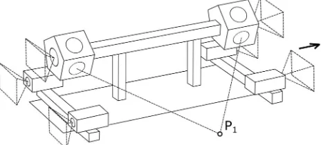
The image-based mobile mapping system (MMS) of the FHNW is being developed since 2009. It has evolved into a multi-stereo camera system mainly used for demanding road and rail infrastructure mapping and management projects (Burkhard et al., 2012). Our novel camera configuration approach allows for a complete 360° stereo image acquisition in heavily built-up urban environments. A forward looking and a backward looking stereo system, consisting of wide-angle pinhole cameras, cover the road with its infrastructure. In addition, two multi-head panoramic cameras tilted forward and backward by 90° each complete the configuration (see Figure 2). The individual heads of the panoramic cameras facing perpendicular to the driving direction build stereo systems which cover pavement and entire façades of buildings even in challenging urban environments.
Figure 2. Novel configuration featuring several stereo camera systems for 360° RGBD mapping (patent pending)
3.1 System description
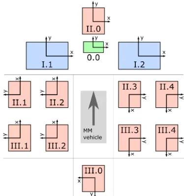
For the following investigations, we configured our MMS with two panoramic heads (II & III) and a single forward-looking stereo camera system (I) with a base of 905 mm (see Figure 3). These cameras have a resolution of 4008 x 2672 pixels (11 MP) at a pixel size of 9 µm, a focal length of about 21 mm and a resulting field-of-view of 81° x 60°. An additional HD camera (0.0) was mounted in the centre between the I.1 and I.2 cameras (see Figure 3) for further investigations, which will not be discussed in this paper. Two tilted multi-head 360° panorama cameras of the type Ladybug5 were setup with a stereo base of 1584 mm for all the individual heads facing perpendicular to the driving direction. Each of the six camera heads of the Ladybug5 camera has a resolution of 2448 x 2048 pixels (5 MP) at a pixel size of 3.45 µm, a focal length of 4.3 mm and a field-of-view of about 113° x 94°.
Figure 3. Outline of our camera setup showing the definitions of image coordinate systems for calibration and processing
Figure 4. Images captured by all cameras at the same location
Ladybug5 panorama cameras consist of five individual heads facing sideways as well as one camera head pointing upward. In our tilted scenario, the two top cameras face either forward or backward (see Figure 3, II.0 and III.0). The five heads pointing sideways constitute five stereo systems. However, the stereo system looking downward mainly maps the MMS vehicle and is
thus omitted (see Figure 4). Consequently, the following stereo camera systems are further processed: forward (I.1 & I.2), left-up (III.1 & II.1), left-down (III.2 & II.2), right-down (II.3 & III.3) and right-up (II.4 & III.4). Figure 3 depicts the modified definitions of image coordinate systems of the Ladybug5 individual heads, which were subsequently used for calibration and image processing.
3.2 Calibration
The required system calibration of our MMS can be subdivided into three tasks:
- calibration of the interior orientation parameters (IOP) for each single camera
- calibration of the relative orientation parameters (ROP) between the left and right cameras of each stereo system - boresight alignment (BA) in order to determine lever arm and
misalignment between the left camera of each stereo system and the reference frame of the navigation system
The standard calibration procedure of our MMS is described in Burkhard et al. (2012). All parameters are estimated using our multi-system and constrained bundle adjustment calibration software which was motivated by the bundle adjustment calibration approach discussed in Ellum & El-Sheimy (2002).
In a first step, we calibrated the IOP and ROP using images captured in our indoor calibration field (see Figure 5, left) featuring well-distributed and signalised targets. For our experiments, the calibration procedure was performed with eight image epochs at different locations by triggering all cameras at the same time. The front camera system (I) and camera 0.0 were introduced into bundle adjustment as perspective cameras with two radial and two tangential distortion parameters. In contrast, all individual heads of both Ladybug5 panorama cameras (II & III) are fisheye cameras for which the equidistant camera model (Abraham & Förstner, 2005) was used. The ROP between the left and right cameras of each stereo system were estimated defining the left cameras as origin. Furthermore, the ROP from each stereo system with respect to the front camera system were computed as well.
In a second step, BA parameters between the front stereo system (I) and the reference frame of the navigation system were determined in our outdoor calibration field (see Figure 5, right) with good GNSS coverage and well signalised 3D control points. The parameters were estimated using bundle adjustment incorporating the previously determined IOP and ROP. Based on the resulting BA parameters as well as on the calibrated ROP between stereo system I and the other stereo systems, BA parameters for each stereo system were computed.
The calibration results listed in Table 1 give an indication of the achievable calibration accuracy. Since all estimated parameters are highly correlated, their separate analysis is not appropriate. The ROP calibration accuracy is influenced by the target point accuracy, the image measurement accuracy, the measuring arrangement and the evidence of the IO model. The accuracy of the boresight alignment is additionally affected by the accuracy of the navigation system. Table 1 shows that the individual Ladybug5 heads (II & III) can be calibrated with the same relative accuracy as the front pinhole cameras (I & 0.0). However, due to the large opening angles of the II & III cameras, the orientation uncertainty of the calibration can affect the variances of the distance component from 1 cm up to 8 cm at a measuring distance of about 10 m depending on the image region.
Cam Calibration parameters
Std. dev. of Position
[mm]
Std. dev. of Orientation [mdeg]
X Y Z ω φ κ
0.0 RO 0.3 0.3 0.5 10.0 20.0 2.0 II & III RO 0.1 0.1 0.2 10.0 7.0 2.0 I RO 0.1 0.1 0.3 13.0 24.0 3.0 I BA 11.7 5.5 6.2 12.0 22.0 6.0
Table 1. Calibration accuracy of relative orientation (RO) as well as boresight alignment (BA) parameters
4. PROCESSING WORKFLOW
One of the main goals of our processing workflow is to obtain accurate Geospatial 3D Images for cloud-based 3D geoinformation services, e.g. for infrastructure management or urban planning. As suggested by Nebiker et al. (2015), a geospatial 3D image consists of a georeferenced RGB image with additional channels supporting depth and quality information, ideally for each pixel. Ideally, 3D images are derived from stereo imagery using dense image matching – in this case from raw equidistant fisheye stereo image pairs – in order to obtain very dense depth representations and to ensure the spatial and temporal coherence of radiometric and depth data. However, alternative approaches for obtaining geospatial 3D images can be considered, e.g. by meshing a LiDAR point cloud and by re-projecting the depth information into image space. A smart way to obtain point clouds from stereo fisheye images was introduced by Schneider et al. (2016). Furthermore, a previous 3D reconstruction employing multiple image sequences could be considered with the advantage of an improved and even more accurate mesh in 3D space (Cavegn & Haala, 2016).
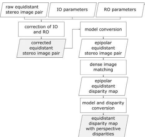
Our implemented image processing workflow is a lightweight and straightforward approach, in order to obtain corrected equidistant RGB images on the one hand and equidistant disparity maps with perspective disparities on the other hand (see Figure 6). The main reason for keeping fisheye images in the equidistant model is to prevent data loss. We assume a model conversion from equidistant to perspective on the client or at the application level. The advantage of a disparity map in comparison with a depth map is the higher resolution at short distances.
After image conversion to the perspective model, 3D points can be determined either by 3D monoplotting based on disparity maps (Burkhard et al., 2012) or by point measurements in both images of the stereo pair.
Figure 6. Workflow for fisheye image processing
Our workflow for stereo fisheye processing is illustrated in Figure 6. First, interior orientation (IO) and relative orientation (RO) are corrected. Parallel epipolar lines are required for stereo image matching algorithms such as semi-global matching (SGM) (Hirschmüller, 2008) or tSGM (Rothermel et al., 2012). Therefore, a previous image model conversion from equidistant to epipolar equidistant is essential (Abraham & Förstner, 2005). After dense image matching, both the geometric image model and disparities have to be reconverted. Image model conversions can be executed with the formulas presented by Abraham & Förstner (2005).
5. PERFORMANCE EVALUATION
In the following sections, an empirical accuracy analysis based on measured 3D points and 3D distances as well as a qualitative assessment of a reconstructed 3D city model based on imagery captured by our MMS configuration are presented.
5.1 Study area
Our study area is located at a very busy junction between five roads in the city centre of Basel, Switzerland. It includes three tramway stops resulting in many overhead wires and it is surrounded by rather tall commercial properties that create a very challenging environment for GNSS positioning. Furthermore, a large number of moving objects in the form of pedestrians, cars, and tramways were present since we acquired the mobile mapping data on a weekday in August 2015 shortly before noon (Cavegn et al., 2016). However, the high acquisition rate leading to along-track distances between successive image exposures of approx. 1 m facilitated mitigating the negative effects caused by these moving objects. Whereas ground control points (GCP) for image-based georeferencing were captured in March 2015, check point coordinates for the evaluation of both relative and absolute accuracy were determined using a total station in July 2016.
5.2 Accuracy analysis
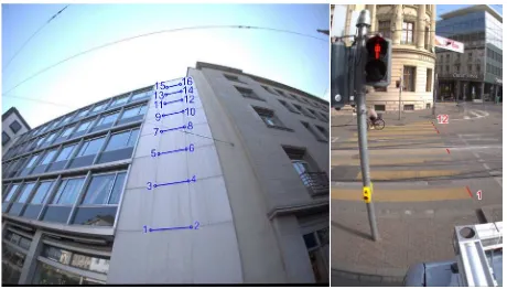
and 12 check points on a pedestrian crossing (see Figure 7, right) were defined. The check points were selected as pairs at different ranges, thus forming reference 3D distances. The points of a point pair on the façade lie more or less at the same distance whereas the 3D distances on the pedestrian crossing vary in viewing direction. This setting allows accuracy analysis with relative as well as with absolute measurements depending on the object distance. While images from the panoramic stereo system 1 (III.1 & II.1, see Figures 3 and 4) were used for the façade, images from the panoramic stereo system 2 (III.2 & II.2) were utilised for the pedestrian crossing. 3D coordinates of check points were determined with manual point measurements in both images, exploiting the IO and RO parameters discussed in chapter 3.2 as well as the exterior orientation parameters from image-based georeferencing (Cavegn et al., 2016). For our investigations, we chose the image-based georeferenced trajectory which was processed with all available 3D points as ground control points (GCP). The GCP RMSE of the trajectory processing range from 1.7 cm to 4.7 cm. While 16 check points were measured as 6 independent samples (n=6) on the façade, 12 check points were determined as 8 independent samples (n=8) on the pedestrian crossing (Ackermann & Studer, 2016).
Figure 7. Layout of reference distances for the accuracy analysis (left: architecture use case, right: road infrastructure use case)
5.2.1 Evaluation of relative accuracy
Relative accuracy, which depends on camera-to-object distances, was determined by comparing photogrammetrically measured 3D distances with reference 3D distances. By the formation of 3D distances, exterior orientation uncertainties of the navigation system are eliminated. Therefore, 3D distances are only affected by the uncertainties of the IO and RO calibration, the uncertainty of the image measurement and the uncertainty of the reference 3D distances. In our investigations, the reference distances were regarded as error-free.
The results of the relative accuracy investigations are depicted in Figure 8. The empirical standard deviations of the distances on the façade lie in the range of 0.5 to 1.5 cm while those on the pedestrian crossing vary between 0.5 and 6.5 cm. It can be seen that the standard deviation of the distances on the pedestrian crossing increases depending on their object distance, whereas no significant object distance-based standard deviation increase occurs for the façade. The main reason for this lies in the horizontal alignment of 3D distances on the façade which also eliminates most parts of the critical error in viewing direction. By contrast, on the pedestrian crossing, the distances are fully influenced by the error of the relative orientation in viewing direction. Another reason is the much clearer point definition on the façade even with increasing distance, which has a positive effect on the image measurement accuracy.
Figure 8. Accuracy of 3D distances depending on object distances
5.2.2 Evaluation of absolute accuracy
For the evaluation of absolute 3D point determination accuracy, photogrammetric point measurements in object space were compared with reference coordinates. Figure 9 depicts that the empirical standard deviation of 3D points increases with object distance. The standard deviations vary between 1 cm and 13 cm. The standard deviations of points on the façade are generally larger than those on the pedestrian crossing even with growing object distance.
Figure 9. Accuracy of 3D points depending on object distances
Generally, the uncertainty of the exterior orientation contributes to the observed standard deviations. Hence, the different standard deviations between our two test fields might be caused by the varying exterior orientation quality. In comparison with previous investigations (Burkhard et al., 2012), which were performed with both HD and 11MP stereo camera configurations as front systems, the results of our investigations do not differ significantly. Consequently, we reached the same accuracy level with our new fisheye stereo camera configuration as with the original 11MP front stereo camera system.
5.3 Automated reconstruction of 3D city models
facilitate the 3D reconstruction process. Furthermore, exterior orientation parameters were calculated for all images using the calibrated BA and ROP. Unwanted fragments of the mobile mapping vehicle were masked in the images. The city model was created with the 3D reconstruction software ContextCapture from Bentley, which also supports a fisheye camera model. For bundle block adjustment, the calibrated interior orientation parameters were fixed while the exterior orientation parameters were re-estimated (Ackermann & Studer, 2016).
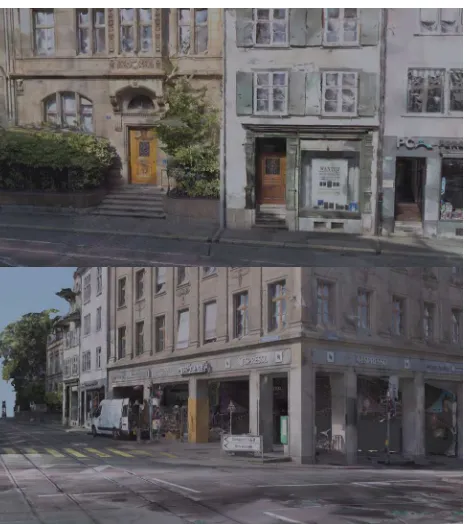
The result of the automatic 3D reconstruction process was a highly detailed 3D city model as shown in Figure 10. Even the detailed façades of the buildings from the classicist epoch are represented almost perfectly. The street with unfavourable geometric and different lighting conditions has been modelled completely as well. As expected, roof reconstruction from the street level imagery is incomplete and noisy. In the future, this gap might be closed by combining MMS images with aerial images as earlier on proposed by Nebiker et al. (2012).
Figure 10. Samples of the reconstructed 3D city model
6. CONCLUSIONS AND OUTLOOK
In this paper, we presented a novel 360° stereo panorama camera configuration for mobile mapping platforms. Two tilted 360° panorama cameras, tilted forward and backward by 90° respectively, enable 360° stereo image acquisition with large baselines. Conventional forward and backward looking stereo systems contribute to a full 360° multi-view stereo coverage. The proposed approach was evaluated by building an image-based mobile mapping system image-based on the new approach. The new mobile mapping system fulfils the accuracy requirements and complies with strict privacy laws, such as in Switzerland. We successfully implemented a rigorous sensor and system calibration procedure, which also supports the equidistant camera model for fisheye lenses. Both the 11MP pinhole cameras of the forward-looking stereo system and the 5MP fisheye heads of the Ladybug5 panorama cameras were
calibrated with the same accuracy. Moreover, the calibration accuracy has been increased significantly compared to Burkhard et al. (2012). Furthermore, in order to generate geospatial 3D images and 3D image spaces (Nebiker et al., 2015) from fisheye stereo images, an image processing workflow was developed according to Abraham & Förstner (2005). We evaluated the accuracies in a challenging urban area in the city centre of Basel using our 360° stereo panorama mobile mapping system. The standard deviations of absolute 3D points were in the range of 4 to 6 cm and those of relative 3D distances were in the range of 1 to 3 cm for typical object distances in the order of 10 m. Our results with fisheye stereo systems do not differ significantly from the results with pinhole stereo systems obtained by Burkhard et al. (2012). With our captured and georeferenced 360° mobile mapping imagery, we created a 3D city model with the 3D reconstruction software ContextCapture from Bentley. The result is a very high detailed and almost complete 3D city model of the street environment. As expected, roofs are incomplete and noisy.
Overall, the novel 360° stereo panorama camera configuration is equivalent in terms of accuracy to the former stereo camera configuration with the advantage of a full 360° stereo coverage. In the future, our ongoing image-based georeferencing developments are expected to significantly improve the demonstrated absolute 3D point determination accuracy. Our developments will also lead to improved orientation accuracies so that we might eventually omit one 360° panorama camera. In this case, stereo images can be created with virtual stereo baselines dependent on vehicle movement. In addition, complete and highly detailed 3D city models could be processed by combining aerial with 360° multi-view mobile mapping imagery.
ACKNOWLEDGEMENTS
This work was financially supported by the Swiss Commission for Technology and Innovation CTI as part of the infraVIS project that was performed in collaboration with iNovitas AG.
REFERENCES
Abraham, S. & Förstner, W., 2005. Fish-eye-stereo calibration and epipolar rectification. ISPRS J. Photogramm. Remote Sens, 59(5), pp. 278–288.
Ackermann, R. & Studer, D., 2016. Stereo-Panorama-Auf-nahmen im urbanen Raum - Untersuchungen mit einem neuen 360°-Stereo-Panoramasystem. Bachelor Thesis. FHNW Univer-sity of Applied Sciences and Arts Northwestern Switzerland, Muttenz, Switzerland (unpublished).
Barber, D., Mills, J. & Smith-Voysey, S., 2008. Geometric validation of a ground-based mobile laser scanning system. ISPRS J. Photogramm. Remote Sens., 63(1), pp. 128–141.
Burkhard, J., Cavegn, S., Barmettler, A. & Nebiker, S., 2012. Stereovision Mobile Mapping : System Design and Performance Evaluation. In: Int. Arch. Photogramm. Remote Sens. Spat. Inf. Sci., Melbourne, Australia, Vol. XXXIX, Part B5, pp. 453–458.
Cavegn, S., Nebiker, S. & Haala, N., 2016. A Systematic Comparison of Direct and Image-Based Georeferencing in Challenging Urban Areas. In: Int. Arch. Photogramm. Remote Sens., Prague, Czech Republic, Vol. XLI, Part B1, pp. 529– 536.
Chen, T., Yamamoto, K., Chhatkuli, S. & Shimamura, H., 2012. Panoramic Epipolar Image Generation for Mobile Mapping System. In: Int. Arch. Photogramm. Remote Sens. Spat. Inf. Sci., Melbourne, Australia, Vol. XXXIX, Part B5, pp. 459–464.
Earthmine, 2014. Earthmine Mars Collection System. http://www.earthmine.com/html/products_mobile.html
(27.3.2017).
Ellum, C.M. & El-Sheimy, N., 2002. The Calibration of Image-Based Mobile Mapping Systems. International Association of Geodesy. 2nd Symposium on Geodesy for Geotechnical and
Structural Engineering, Berlin.
Eugster, H., Huber, F., Nebiker S. & Gisi, A., 2012. Integrated Georeferencing of Stereo Image Sequences Captured with a Stereovision Mobile Mapping System – Approaches and Practical Results from a Practical Perspective. In: Int. Arch.
Photogramm. Remote Sens. Spatial Inf. Sci., Melbourne,
Australia, Vol. XXXIX, Part B1, pp. 309–314.
Haala, N., Peter, M., Kremer, J. & Hunter, G., 2008. Mobile LiDAR Mapping for 3D Point Cloud Collection in Urban Areas - A Performance Test. In: Int. Arch. Photogramm. Remote Sens. Spatial Inf. Sci., Beijing, China, Vol. XXXVII, Part B5. pp. 1119–1124.
Heuvel, F.A. Van Den, Verwaal, R. & Beers, B., 2006. Calibration of Fisheye Camera Systems and the Reduction of Chromatic Aberration. In: Int. Arch. Photogramm. Remote Sens. Spatial Inf. Sci., Dresden, Germany, Vol. XXXVI, Part 5.
Hirschmüller, H., 2008. Stereo Processing by Semiglobal Matching and Mutual Information. IEEE Trans. Pattern Anal. Mach. Intell., 30(2), pp. 328–341.
Kannala, J. & Brandt, S.S., 2006. A generic camera model and calibration method for conventional, wide-angle, and fish-eye lenses. IEEE Trans. Pattern Anal. Mach. Intell., 28(8), pp. 1335–1340.
Krombach, N., Droeschel, D. & Behnke, S., 2015. Evaluation of Stereo Algorithms for Obstacle Detection with Fisheye Lenses. In: Int. Ann. Photogramm. Remote Sens. Spatial Inf. Sci., Toronto, Canada, Vol. II-1/W1, pp. 33–40.
Luber, A., 2015. Ein generisches Abbildungsmodell für Stereokamerasysteme. PhD Thesis. Humboldt-Universität zu Berlin.
Lui, W.L.D. & Jarvis, R., 2010. Eye-Full Tower: A GPU-based variable multibaseline omnidirectional stereovision system with automatic baseline selection for outdoor mobile robot navigation. Rob. Auton. Syst., 58(6), pp. 747–761.
Meilland, M., Comport, A.I. & Rives, P., 2015. Dense Omnidirectional RGB-D Mapping of Large-scale Outdoor Environments for Real-time Localization and Autonomous Navigation. J. F. Robot., 32(4), pp. 474–503.
Nebiker, S., Cavegn, S., Eugster, H., Laemmer, K., Markram, J. & Wagner, R., 2012. Fusion of Airborne and Terrestrial Image-based 3D Modelling for Road Infrastructure Management – Vision and First Experiments. In: Int. Arch. Photogramm. Remote Sens. Spatial Inf. Sci., Melbourne, Australia, Vol. XXXIX, Part B4, pp. 79–84.
Nebiker, S., Cavegn, S. & Loesch, B., 2015. Cloud-Based Geospatial 3D Image Spaces—A Powerful Urban Model for the Smart City. ISPRS Int. J. Geo-Information, 4(4), pp. 2267– 2291.
Novak, K., 1991. The Ohio State University Highway Mapping System: The Stereo Vision System Component. In: Proc. of the
47th Annual Meeting of The Institute of Navigation,
Williamsburg, VA, pp. 121–124.
NovAtel, 2012. Span-SE User manual. No. OM-20000124. Calgary, Alberta, Canada.
Paparoditis, N., Papelard, J.-P., Cannelle, B., Devaux, A., Soheilian, B., David, N. & Houzay, E., 2012. Stereopolis II: A Multi-Purpose and Multi-Sensor 3D Mobile Mapping System for Street Visualisation and 3D Metrology. Rev. française photogrammétrie télédétection, 200, pp. 69–79.
Puente, I., González-Jorge, H., Martínez-Sánchez, J. & Arias, P., 2013. Review of mobile mapping and surveying technologies. Measurement, 46(7), pp. 2127–2145.
Rothermel, M., Wenzel, K., Fritsch, D. & Haala, N., 2012. SURE - Photogrammetric Surface Reconstruction from Imagery. In: Proceedings LC3D Workshop, Berlin, pp. 1–21.
Schneider, J., Stachniss, C. & Förstner, W., 2016. On the Accuracy of Dense Fisheye Stereo. IEEE Robot. Autom. Lett., 1(1), pp. 227–234.
Schwarz, K.P., Martell, H.E., El-Sheimy, N., Li, R., Chapman, M.A. & Cosandier, D., 1993. VIASAT - A Mobile Highway Survey System of High Accuracy. In: Proceedings of the
Vehicle Navigation and Information Systems Conference,
Ottawa, pp. 476–481.