______________________________ * Corresponding author.
COMPARISON OF TARGET- AND MUTUAL INFORMATON BASED CALIBRATION
OF TERRESTRIAL LASER SCANNER AND DIGITAL CAMERA
FOR DEFORMATION MONITORING
Mohammad Omidalizarandi* and Ingo Neumann
Geodetic Institute, Leibniz Universität Hannover, Germany – (zarandi, neumann)@gih.uni-hannover.de
Commission I, WG I/4
KEY WORDS: Terrestrial Laser Scanner, Digital Camera, Extrinsic Calibration, Bundle Adjustment, Mutual Information
ABSTRACT:
In the current state-of-the-art, geodetic deformation analysis of natural and artificial objects (e.g. dams, bridges,...) is an ongoing research in both static and kinematic mode and has received considerable interest by researchers and geodetic engineers. In this work, due to increasing the accuracy of geodetic deformation analysis, a terrestrial laser scanner (TLS; here the Zoller+Fröhlich IMAGER 5006) and a high resolution digital camera (Nikon D750) are integrated to complementarily benefit from each other. In order to optimally combine the acquired data of the hybrid sensor system, a highly accurate estimation of the extrinsic calibration parameters between TLS and digital camera is a vital preliminary step. Thus, the calibration of the aforementioned hybrid sensor system can be separated into three single calibrations: calibration of the camera, calibration of the TLS and extrinsic calibration between TLS and digital camera. In this research, we focus on highly accurate estimating extrinsic parameters between fused sensors and target- and targetless (mutual information) based methods are applied. In target-based calibration, different types of observations (image coordinates, TLS measurements and laser tracker measurements for validation) are utilized and variance component estimation is applied to optimally assign adequate weights to the observations. Space resection bundle adjustment based on the collinearity equations is solved using Gauss-Markov and Gauss-Helmert model. Statistical tests are performed to discard outliers and large residuals in the adjustment procedure. At the end, the two aforementioned approaches are compared and advantages and disadvantages of them are investigated and numerical results are presented and discussed.
1. INTRODUCTION
In the current state-of-the-art, geodetic deformation analysis of natural and artificial objects (e.g. dams, bridges, towers, railroads, landslides,...) is an ongoing research in both static and kinematic mode. In this research, due to increasing the accuracy of geodetic deformation analysis, TLS and a high resolution digital camera are integrated to complementarily benefit from each other. On the one hand, TLS can provide high resolution 3D data in the sub-millimetre range in combination with reflectivity values. Consequently, a reflectance image can be generated using central perspective representation to project the 3D point clouds to a virtual image plane. On the other hand, digital camera can acquire rich and high quality colour images. In the integrated sensor system, high resolution cameras are advantageous due to having high angular accuracy of sub-pixel accuracy image measurements which would improve the lateral accuracy of laser scanners (Schneider & Maas, 2007). In addition, this integration focuses at filling gaps in TLS data to compensate modeling errors and to reconstruct more details in higher resolution (Moussa et al., 2012).
The main purpose of this research is to high accurately estimate extrinsic parameters between TLS and digital camera to compensate the deficiency of the TLS measurements for deformation monitoring of the objects, e.g. in case of large incidence angle, by using high resolution camera. Furthermore, digital images would assist us to detect deformation analysis in both direction of laser beam and perpendicular to laser beam. Moreover, this integration leads to increasing redundancy in the adjustment procedure.
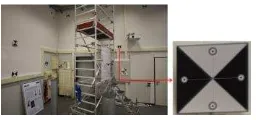
In order to ideally relate digital camera coordinate frame to the TLS coordinate frame, the digital camera is mounted on top of the TLS using clamping system (figure 1, right). To avoid any vibration of digital camera and blurring of images, Nikon wireless mobile utility application is setup on the cell phone and by the usage of Wi-Fi connection, photographs are captured indirectly.
Figure 1. The employed sensors. Laser tracker (left), A D750 digital camera and Z+F Imager 5006 TLS and their
corresponding coordinate systems (right)
The calibration of the aforementioned hybrid sensor system can be separated into three single calibrations: calibration of the camera, calibration of the TLS and extrinsic calibration between TLS and digital camera. The interior orientation of the camera and internal error sources of the TLS can be determined in the laboratory to reach high accurate calibration values. However, The International Archives of the Photogrammetry, Remote Sensing and Spatial Information Sciences, Volume XL-1/W5, 2015
external error sources especially atmospheric and object related errors could not be considered in the laboratory and need on-site calibration to be removed as well.
Unnikrishnan and Hebert (2005) described the algorithm to estimate the extrinsic calibration parameters of a camera with respect to a laser rangefinder using checkerboard calibration targets. In this method, a plane fits to the manually selected targets on the checkerboard pattern and aligned it with the detected pattern of the image using optimization algorithm. Moussa et al. (2012) proposed an automatic procedure to combine TLS and digital camera based upon free registration using ASIFT and RANSAC algorithm to match reflectance image and RGB image. Absolute camera orientations are obtained on the basis of space resection method. Lichti et al. (2010) presented the self-calibration of the range camera with respect to the rangefinder in a free-network bundle adjustment using signalized targets. Variance component estimation is applied to optimally re-weight observations iteratively. Pandey et al. (2012) proposed the automatic targetless extrinsic calibration of a Velodyne 3D laser scanner and Ladybug3 omnidirectional camera on the basis of the mutual information (MI) algorithm to estimate extrinsic calibration parameters by maximizing the mutual information between the reflectivity values of the laser scanner and intensity values of the camera image. Taylor and Nieto (2012) proposed a method to compute extrinsic and intrinsic calibration parameters between camera and LIDAR scanner. This approach utilizes normalised mutual information to compare images with the laser scans projections. Particle swarm optimization algorithm is applied to optimally determine the parameters.
In this research, we focus on highly accurate estimation of the extrinsic parameters between TLS and digital camera which is necessary and preliminary step for deformation monitoring. Two different strategies of target- and MI based are applied. In target-based approach, focal length of the camera, exterior orientation parameters between TLS and camera (position and orientation; 6 DOF), exterior orientation parameters between TLS and laser tracker (scale, position and orientation; 7 DOF) and target coordinates are estimated with high accuracy. Laser tracker (LT (figure 1, left)) measurements are carried out with superior accuracy and independently. In addition, its measurements are considered as a reference coordinate frame. In MI-based approach, extrinsic calibration parameters between TLS and digital camera are obtained with adaptation and modification of the Pandey’s work to our research purpose by considering horizontal angle measurement of the TLS as additional parameter into the transformation matrix.
2. DATA ACQUISITION, INTERFACING AND
PRE-PROCESSING
In the target-based approach, data acquisition step comprises image measurements, TLS measurement and LT measurements. In the MI-based approach, it consists of the RGB image from the digital camera and generated reflectance image from the TLS reflectivity values.
Images are captured with Nikon D-750 24.3 megapixel digital camera and centre of each target is computed based upon detection of the four centriods of the circles within each target and performing averaging. For instance, an exemplary target with detected centriods is illustrated in figure 2. Afterwards, extracted image measurements are rectified based on well known Brown’s equations to eliminate the effects of radial and decentring distortions.
Figure 2. Calibration room (left) depiction of detected centroid of circles using sub-pixel target mode of the PhotoModeler
software (right)
TLS point targets accurately acquired using “Fit target” mode of the Z+F LaserControl software.
The horizontal angle measurement of the TLS (Az) is defined as a 3x3 rotation matrix to rotate TLS coordinate frame around its Z-axis to the digital camera coordinate frame (Al-Manasir and Fraser (2006)). It is written for each captured image and can be considered as additional observation in the adjustment procedure. As can be seen in figure 1 (right), TLS coordinate frame, digital camera coordinate frame and Az are depicted. LT measurements are utilized as an additional observation and they are obtained by pointing to the mounted corner cubes which are located at the centre of each target.
Reflectance images can be generated based on the scanning matrix and central perspective representation. In the first approach, each 3D data is assigned to one pixel based on the scan resolution. It is quite simple and fast. However, as a drawback, straight lines appear as curved lines (Meierhold et al., 2010). In the second approach, TLS data is projected to a virtual image plane on the basis of the collinearity equation (Moussa et al., 2012).
Figure 3. Definition of coordinate systems (Meierhold et al., 2010)
As can be seen in figure 3, the maximum and minimum horizontal angle of the TLS is determined to reduce the size of the entire scan of TLS data to project into the image space. In the figure 4, rectified image and generated reflectance image from TLS data are depicted.
Figure 4. Rectified image (left), Reflectance image from TLS (right)
3. METHODOLOGY
3.1 Target-based calibration
In the target based approach, focal length of the camera, extrinsic parameters between TLS and camera, extrinsic parameters between TLS and LT and target coordinates are estimated as unknown parameters. In order to obtain exterior The International Archives of the Photogrammetry, Remote Sensing and Spatial Information Sciences, Volume XL-1/W5, 2015
orientation parameters between TLS and digital camera, space resection bundle adjustment is employed based upon collinearity equations to determine the condition that a perspective centre, a point in the image space and its corresponding coordinate in the object space are on a straight line (equations 1 & 2). Since aforementioned equations are non-linear with respect to the parameters, it needs to be non-linearized to compute parameters iteratively. Therefore, initial starting values are estimated using direct linear transform (DLT) in combination of RANSAC algorithm to robustly estimate the parameters. In addition, the mathematical model to estimate the exterior orientation parameters between TLS and LT is solved based on similarity transformation (equation 3). Furthermore, additional constraint is defined to compute target point coordinates in the object space (equation 4). Thus, least square solutions are computed by means of the Gauss-Markov model (GM) and Gauss-Helmert model (GH). Therefore, four target functions (equations 1-4) are determined as follow:
� = − � (1)
In equations (1-6), , are the target coordinates in the image space, ( , , ) are the target coordinates in the object space, are the rotation angles between TLS and LT and ( ) is the scale factor between TLS and LT.
GM model is a set up linear or non linear relation between observations and unknown parameters. It is merely determined by observations to estimate unknown parameters. In this type of least square adjustment, square sum of residuals are minimized for one type of observation (image measurements). GH model is more complete and sophisticated model compared to GM model and comprising all the unknown parameters and observations that can be updated as unknowns iteratively.
3.1.1 Gauss-Markov model: In this research, GM model is solved based on equations 1 & 2. In equation 7, v is a vector of residuals, A is a matrix of the coefficients of the unknowns of the observations and unknowns in the target functions and it is denoted as:
�(�̂, ̂) = + + ̂ (9)
Where �̂ is estimated observation vector, ̂ � estimated unknown vector, A matrix is derivative with respect to the unknown parameters, B matrix is derivative with respect to the observations and w is the vector of misclosures. Thereafter, unknown parameters are computed as follows:
[�̂] = −[ �� ] −
. [ ] (10)
Where ̂ is the estimated reduced unknown vector. Moreover, vector of residuals are computed by:
= �� � (11)
3.1.3 Variance Component Estimation and Statistical Test: Variance component estimation is applied to assign optimal weights to the observations in the adjustment procedure iteratively. The statistical test is performed to investigate the adjustment results. Additionally, the uncertainty of the measurements and unknown parameters is computed. In this research, and � test with 95% confidence level are applied to detect outliers.
3.2 Mutual Information-based Calibration
Mutual information (MI) is used to detect statistical dependencies or a measure of coupling between signals (Pompe et al., 1998). MI is defined on the basis of Shannon's definition of entropy (equation 13) and is interpreted based upon the amount of information and event that occurs, the uncertainty about the result of an event, and the dispersion of the probabilities when the event occurs (Alempijevic et al., 2006).
H= ∑ �*log � �
(13)
Where � is the probability mass function of random variable i. The International Archives of the Photogrammetry, Remote Sensing and Spatial Information Sciences, Volume XL-1/W5, 2015
In this work, MI is determined on the basis of the entropy of reflectance image (H(A)), entropy of RGB image (H(B)) and H(A,B) as a joint entropy (equation 14) and generally it means the amount of information that A contains about B. MI is maximized by maximizing the terms H(A) and H(B) and minimizing the H(A,B).
MI(A,B) = H(A) + H(B) - H(A,B) (14)
where
H(A) = H(p(a)) =∑pa*logp1
a a
(15)
H(B) = H(p(b)) =∑pb*logp1
b b
(16)
H(A,B) = H(p(a,b)) =∑ ∑p(a,b)
b
*logp(a,b)1
a
(17)
In equations (15-17), a and b are the real numbers of the events that random observations A and B of a probabilistic experiment are mapped onto them (Pandey, 2014). MI based approach is an automatic procedure that is usually applied in outdoor calibration without any need of mounted targets in the field. In this approach, extrinsic calibration parameters are estimated by maximizing the mutual information between reflectance image of TLS and RGB image of the digital camera and correlation coefficients are computed. Then, different scan measurements from different horizontal angle measurements of TLS are considered in a single optimization framework and the parameters of interest are computed by means of the gradient ascent algorithm (Pandey et al., 2012).
The main goal of the author is to apply MI based approach for in situ calibration to eliminate systematic errors (e.g. clamping system) and consequently avoiding target based calibration in the field. In order to adapt pandey’ algorithm to our work, Az included as additional parameter in the transformation matrix to re-project 3D point clouds to the 2D image correctly. Thus, equation 5 is utilized to perform this projection.
As a drawback of this method, it cannot be applied directly to range sensors without associated reflectivity information. Furthermore, it needs quite good initialization values of 6 DOF. Moreover, in case of speed up of the algorithm, it is significantly slower than target based approach. In addition, in order to obtain better results, reflectivity values of the TLS need to be calibrated in addition to image enhancement and filtering of the RGB image (e.g. brightness and contrast).
4. EXPERIMENTS AND RESULTS
In this research, two different approaches of target- and MI- based are investigated in two case studies. In the first case study, two different adjustment models (GM and GH models) are solved. GM model is just implemented as preliminary test to achieve primary results very fast. But, due to more complete and accurate results of the GH model compared to the GM model, merely its results from target-based approach are presented. In the second case study, MI based approach from Pandey’s work is adapted to this research and its results are presented and discussed.
For the experiments, a calibration room is measured with Z+F IMAGER 5006 in the super high resolution mode with horizontal and vertical angle resolution of . °. It has the maximum field of view of 3 °× 3 ° in horizontal and
vertical respectively and its accuracy is . ° rms. Thereafter, 84 images are captured with Nikon D750 digital camera to fully cover our calibration room. Targets are measured in the both image and object space, respectively. The number of measured targets in object space is 25 and number of measured targets in the image space is 395. LT is utilized for validation and check the accuracy of our calibration results with the super high accuracy.
4.1 Case Study I:
In this case study, least square solution is solved on the basis of GH model. Employed sensors are TLS, LT and digital camera. Observations are target coordinates in the image space, TLS coordinates of the targets, LT coordinates of the targets and horizontal angle measurements of TLS. Extrinsic parameters between TLS and digital camera (table 1), extrinsic parameters between TLS and LT (table 2), focal length and target point coordinates in object space are the unknown parameters.
6 DOF Value �
88.7180 (Deg.) 0.0032 0.11965 (Deg.) 0.0045 0.04651 (Deg.) 0.0018
� -0.0021 (m) 0.0003
� 0.2195 (m) 0.0002
� 0.0956 (m) 0.0001
Table 1. Extrinsic parameters between TLS and digital camera (6 DOF) using GH model
7 DOF Value �
′ 0.10599 (Deg.) 0.0007
′ -0.0611 (Deg.) 0.0012
′ 96.3559 (Deg.) 0.0012
�′ 12.8276 (m) 0.0001
�′ 13.9031 (m) 0.0001
�′ 1.6952 (m) 0.0001
0.9999 2.03e-05
Table 2. Extrinsic parameters between TLS and LT (7 DOF) using GH model
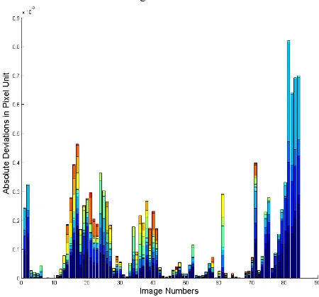
Figure 5. Absolute deviations of the re-projected estimated TLS data and estimated image targets in pixel unit Figure 5 is illustrated to visualize the accuracy of the implemented space resection bundle adjustment algorithm. It The International Archives of the Photogrammetry, Remote Sensing and Spatial Information Sciences, Volume XL-1/W5, 2015
shows the absolute deviations of the re-projected estimated TLS data and estimated image targets in pixel unit. As can be seen from Y-axis, the deviations are in sub-pixel range which indicates that constraints of the adjustment are fulfilled.
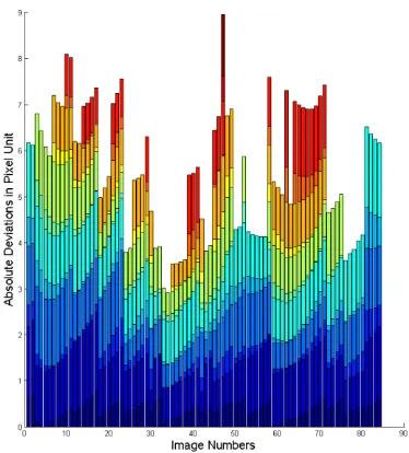
Figure 6. Absolute deviations of the estimated image targets and image targets measurements in pixel unit
In the figure 6, the absolute deviations of the estimated image targets and image targets measurements in pixel unit is depicted. X-axis corresponds to image numbers and Y-axis corresponds to absolute deviations in pixel unit. For each image, all the targets with their deviations in x and y directions are considered in one column. For instance, in the first column of the figure 6, image one contains three targets which with consideration of their deviations in x and y directions respectively, six colourful blocks are shown. In addition, the maximum magnitude belongs to image 11 since it contains six targets.
Variance component estimation leads to obtain accurate standard deviations of the observation. As we can see in table 3, standard deviation of the image measurements is in sub-pixel range since the resolution of the captured images is 0.006 mm. In addition, standard deviation of the TLS measurements is close to half millimeter since we were close to the targets (less than 6 meter) in our laboratory and experiencing less systematic errors. Concerning the Az of the TLS is a bit worse than its nominal value in the user manual that is . ° since it is written down with 0.001 decimal degree from the display screen of the TLS. Moreover, as we expected, standard deviation of the LT measurements is close to 0.1 mm. Furthermore, A-posteriori variance factor of unit weight (�̂ is computed for entire measurements and that is equal to 0.8975.
Observations � − before adjustment
� − after adjustment
Image meas. (mm) 0.0243 0.0053
TLS meas. (mm) 1.0 0.4809
LT meas. (mm) 0.1 0.0835
Az meas. (Degree) 0.03599 0.0100
Table 3. Standard deviations of the observations
As can be seen in figure 7, residuals for all type of the observations (image measurements, TLS measurements, LT measurements and horizontal angle measurements of the TLS) are illustrated. Furthermore, some of the LT measurements
residuals are too large which we will investigate them in the future.
Figure 7. Residuals of the observations
In figure 8, re-projection of the downsampled point clouds into the rectified image by the usage of calibration parameters is illustrated.
Figure 8. Re-projection of downsampled point clouds into the rectified image using estimated extrinsic parameters of the
calibration
4.2 Case Study II:
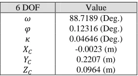
In the second case study, MI based approach as an alternative approach is applied to compare it with high accurate target based approach. In addition, author is investigating about applicability of MI based approach for in field calibration. In this work, we examine the MI based approach merely for one image. Extrinsic parameters between TLS and digital camera are indicated in table 4.
6 DOF Value
88.7189 (Deg.) 0.12316 (Deg.) 0.04646 (Deg.)
� -0.0023 (m)
� 0.2207 (m)
� 0.0964 (m)
Table 4. Extrinsic parameters between TLS and digital camera (6 DOF) – MI based approach
Figure 9. Absolute deviations of the re-projected estimated TLS data and estimated image targets in pixel unit - MI based
approach
In the figure 9, absolute deviations of the re-projected estimated TLS data and estimated image targets in pixel unit is indicated. As can be seen, estimated extrinsic parameters in MI based approach is not as accurate as target based approach and it leads to increasing the deviations.
∆ � (m)
∆ � (m)
∆ � (m)
∆ (Deg.)
Δ (Deg.)
Δ (Deg.) 0.0002 -0.0012 -0.0007 -0.0009 -0.0035 5.0e-05
Table 5. Deviations of 6 DOF in the two aforementioned approaches
In the table 5, deviations of extrinsic calibration parameters (6 DOF) between two approaches are indicated. These deviations can be related to the sensors noises or uncertainties of the measurements and unknown parameters. Furthermore, it can be due to remaining outliers and also considering just one image in the MI-based approach.
CONCLUSION
The main objective of this research is to obtain extrinsic parameters between fused sensors (TLS, digital camera and LT). Two different methodology of target based and MI based are applied. As a result of the first methodology, GH model is more accurate comparing to the GM model since we have this possibility to use different types of the observations with different weights in the non linear relations to the parameters. In addition, variance component estimation assists us to automatically assign adequate weights to the observations iteratively and consequently arising high accurate adjustment results. Moreover, statistical tests are beneficial due to rejecting outliers and large residuals which are above the pre-determined test value. MI based approach is come up with the lower accuracy results compared to the target based approach and it did not fully satisfy our purpose for in situ calibration and needs more efforts and investigations.
In the future work, MI based approach for numerous scans and images should be investigated. In addition, high accurate extrinsic parameters from target based approach are utilized in
deformation monitoring and analysis to exploit the possibility of images and TLS data simultaneously.
REFERENCES
Alempijevic, A., Kodagoda, S., Underwood, J., Kumar, S., & Dissanayake, G. (2006). Mutual information based sensor registration and calibration. In Intelligent Robots and Systems, 2006 IEEE/RSJ International Conference on IEEE, pp. 25-30.
Al-Manasir, K., & Fraser, C. S. (2006). Registration of terrestrial laser scanner data using imagery. The Photogrammetric Record, 21(115), 255-268.
Lichti, D. D., Kim, C., & Jamtsho, S. (2010). An integrated bundle adjustment approach to range camera geometric self-calibration. ISPRS Journal of Photogrammetry and Remote Sensing, 65(4), 360-368.
Meierhold, N., Spehr, M., Schilling, A., Gumhold, S., & Maas, H. G. (2010). Automatic feature matching between digital images and 2D representations of a 3D laser scanner point cloud. Int. Arch. Photogramm. Remote Sens. Spat. Inf. Sci, 38, 446-451.
Moussa, W., Abdel-Wahab, M., & Fritsch, D. (2012). An Automatic Procedure for Combining Digital Images and Laser Scanner Data. International Archives of the Photogrammetry, Remote Sensing and Spatial Information Sciences, 39, B5.
Niemeier, W. (2002). Ausgleichungsrechnung: eine Einführung für Studierende und Praktiker des Vermessungs-und Geoinformationswesens. Walter de Gruyter, Berlin.
Pandey, G., McBride, J. R., Savarese, S., & Eustice, R. (2012). Automatic Targetless Extrinsic Calibration of a 3D Lidar and Camera by Maximizing Mutual Information. Proceedings of the AAAI National Conference on Artificial Intelligence, pp. 2054-2056. C++ source code is available from:
http://robots.engin.umich.edu/SoftwareData/ExtrinsicCalib
Pandey, G. (2014). An Information Theoretic Framework for Camera and Lidar Sensor Data Fusion and its Applications in Autonomous Navigation of Vehicles, Doctoral dissertation, The University of Michigan. Available from:
http://deepblue.lib.umich.edu/handle/2027.42/107286
Pompe, B., Blidh, P., Hoyer, D., & Eiselt, M. (1998). Using mutual information to measure coupling in the cardiorespiratory system. Engineering in Medicine and Biology Magazine, IEEE, 17(6), 32-39.
Schneider, D., & Maas, H. G. (2007). Integrated bundle adjustment of terrestrial laser scanner data and image data with variance component estimation. The Photogrammetric Journal of Finland, 20, 5-15.
Taylor, Z., & Nieto, J. (2012). A mutual information approach to automatic calibration of camera and lidar in natural environments. In Australian Conference on Robotics and Automation, pp. 3-5.
Unnikrishnan, R., & Hebert, M. (2005). Fast extrinsic calibration of a laser rangefinder to a camera. Technical report CMU-RI-TR-05-09, Robotics Institute, Carnegie Mellon University