AUTOMATED MOSAICKING OF MULTIPLE 3D POINT CLOUDS
GENERATED FROM A DEPTH CAMERA
H. Kim, W. Yoon, T. Kim
Dept. of Geoinformatic Engineering, Inha University, 100 Inharo, Namgu, Incheon, Korea (khanai91, rainnydayz)@inha.edu, [email protected]
Commission III, WG III/2
KEY WORDS: Depth Camera, Point Cloud, Mosaicking, Tiepoint, Similarity transformation,
ABSTRACT:
In this paper, we propose a method for automated mosaicking of multiple 3D point clouds generated from a depth camera. A depth camera generates depth data by using ToF (Time of Flight) method and intensity data by using intensity of returned signal. The depth camera used in this paper was a SR4000 from MESA Imaging. This camera generates a depth map and intensity map of 176 x 44 pixels. Generated depth map saves physical depth data with mm of precision. Generated intensity map contains texture data with many noises. We used texture maps for extracting tiepoints and depth maps for assigning z coordinates to tiepoints and point cloud mosaicking. There are four steps in the proposed mosaicking method. In the first step, we acquired multiple 3D point clouds by rotating depth camera and capturing data per rotation. In the second step, we estimated 3D-3D transformation relationships between subsequent point clouds. For this, 2D tiepoints were extracted automatically from the corresponding two intensity maps. They were converted into 3D tiepoints using depth maps. We used a 3D similarity transformation model for estimating the 3D-3D transformation relationships. In the third step, we converted local 3D-3D transformations into a global transformation for all point clouds with respect to a reference one. In the last step, the extent of single depth map mosaic was calculated and depth values per mosaic pixel were determined by a ray tracing method. For experiments, 8 depth maps and intensity maps were used. After the four steps, an output mosaicked depth map of 454x144 was generated. It is expected that the proposed method would be useful for developing an effective 3D indoor mapping method in future.
1. INTRODUCTION
In recent day, the technology of handling 3D point clouds is gaining industrial and public attentions. Handling 3D point clouds is an important task in 3D indoor mapping, robotics as well as geometrics. There are several methods to generate 3D point clouds. In photogrammetric engineering, matching of stereo images or laser scanning has been used for generating 3D point clouds. However, for indoor environments, these methods may not be easily applied. For matching, indoor images may not have sufficient texture. For laser scanning, there is a problem of cost and scanning speed.
As an alternative, we selected to use a depth camera as a method for 3D point cloud generation. In this approach, we can have an advantage that we do not need to hire sophisticated matching process for depth calculation.
A depth camera usually has small field of view and small number of pixels. To use a depth camera for indoor scanning, it is necessary to combine individual depth scenes into a complete 3D point cloud. As a first attempt for such combination, we tackle the problem of how to mosaic individual 3D point clouds. Mosaicking of individual 2D images has been studied previously (Yehuda and Ariel, 1998). In this paper, we propose a new method of automated mosaicking of multiple 3D point clouds generated from a depth camera.
2. CHRACTERISTIC OF DEPTH CAMERA
2.1 Principle of Estimating Distance Using Depth Camera
Because our method uses a depth camera, we first introduce the principle of distance measurement using a depth camera. A depth camera emits infrared rays, which will be reflected by the objects. A depth camera detects the reflected rays and measures the phase difference. From these steps, we can calculate the distance between the camera and the objects. The phase difference in wavelengths is calculated from the relationship among different 4 electron charges and phase control signals have 90 of phase lag to each other. The phase difference from those electron charges could be calculated through Eq. (1).
t tan ΩΩ ΩΩ (1)
where Ω , Ω , Ω , Ω = control signal
We can calculate the distance through Eq. 2 when speed of light(c) and frequency are given. And ⁄2 is maximum distance that depth camera can estimate without ambiguity.
d 2 2 (2)
where c = speed of light f = focal length t = difference of phase
The International Archives of the Photogrammetry, Remote Sensing and Spatial Information Sciences, Volume XLI-B3, 2016 XXIII ISPRS Congress, 12–19 July 2016, Prague, Czech Republic
This contribution has been peer-reviewed.
2.2 Depth Camera’s Error
Because of the depth camera design, an image generated from a depth camera has systematic errors and non-systematic errors as shown in figure 1. Systematic error depends on sensor’s characteristics such as intensity of emitted IR signal, data collecting time and temperature. Non-systematic error depends on the object characteristics such as color, surface and quality of the object.
Figure 1. Errors of depth camera image
2.3 Equipment
In this paper, we choose a MESA SR4000 for a depth camera. It generates depth map and intensity map of 176 x 144 pixels that has a precision that 16bit floating points. This depth camera can estimate distance upto 10 meter and the detail information are in Table 1.
Table 1. MESA SR4000 Specification
3. DEPTH MAP MOSAICKING
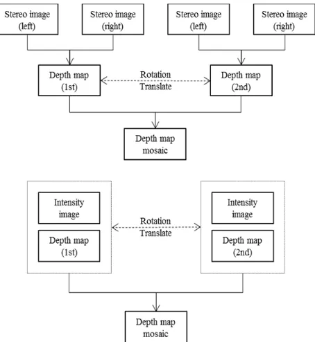
There is an important difference between mosaicking depth camera’s output and mosaicking of general stereo camera’s output. Figure 2 shows process of each method. In case of stereo camera, relative orientation between stereo images is estimated and stereo matching is applied to generate 3D point clouds. For mosaicking depth map images, these processes can be skipped since the camera generates a depth map as well as an intensity map. Therefore the whole processing chain can be simplified. On the other hands, an intensity map available from a depth camera has very poor quality compared to the image from general stereo camera. Therefore automated tiepoint extraction from a depth camera could be challenging.
For mosaicking, we need to estimate geometric relationship between two dataset. For 2D-2D image mosaicking, we can use affine, homography or coplanar models for the geometric relationship. In our case, we aim to mosaic 3D point clouds. We need to estimate 3D geometric relation between the two dataset.
We will use 3D similarity transformation for the relation. This process may also be challenging in that we need to convert 2D tiepoints into 3D by attaching depth value for the tiepoint. Depth errors will be introduced to 3D tiepoints. Precise estimation of 3D-3D transformation with noisy 3D tiepoints is also challenging.
We propose the following five steps to mosaic depth maps.
Figure 2. Process of mosaicking stereo images and depth maps.
3.1 Taking Image
We take multiple images from a depth camera by installing the camera on a tripod and by rotating the camera. We set a depth camera on a tripod to eliminate possible height variation among perspective centers of each scene. After finishing setting, we rotate camera clockwise or counterclockwise.
A depth map and an intensity map are generated from the source data after removing some system noise and correcting for lens distortion.
3.2 Extracting Tiepoints
As mentioned, we have to know relationships between adjacent maps for mosaicking. To estimate the relationships, we first apply tiepoint extraction. It is very important that there is enough texture information to extracting tiepoints.
We extracted tiepoints between adjacent images by using FAST for detecting keypoints and SIFT as a descriptor and matching. FAST algorithm decides features by considering a circle of sixteen pixels around interested points (Edward et al., 2006). SIFT algorithm selects features like corner point and extracts characteristic vectors from local patch around features (David and Lowe, 2004)
3.3 Generating 3D Coordinate
Extracted tiepoints are expressed as 2D image coordinates (C, R). But the transformation relationship between depth maps is
The International Archives of the Photogrammetry, Remote Sensing and Spatial Information Sciences, Volume XLI-B3, 2016 XXIII ISPRS Congress, 12–19 July 2016, Prague, Czech Republic
This contribution has been peer-reviewed.
3D-3D transformation. It means that we have to convert the tiepoint’s coordinates into a 3D coordinates. We used a depth value of the tiepoint pixel and use Eq. 3 for converting 2D image coordinate (C, R) to 3D coordinates (X, Y, Z) in camera frame.
X
Y Z
(3)
where , = image coordinates of principal point F = focal length / ccd size
3.4 Estimating Transformation Coefficients
Converted 3D coordinates per each depth map are in individual camera frames. We have to unify every depth map’s coordinate frames for mosaicking depth maps. As mentioned above, we used 3D similarity transformation for this step ( Eq. 4).
, , (4)
where , , = image coordinates of principal point In Eq. 4, we estimate scale, b , b , b , , , through least square estimation. To handle outliers due to noisy tiepoints and noisy depth of tiepoints, a robust estimation based on RANSAC algorithm was applied. This step estimates transformation coefficients between adjacent maps.
3.5 Making Depth map Mosaic
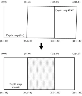
After all depth map model’s transformation coefficients are estimated, we have to make a depth map mosaic. We may set the area of mosaic image as expanding first captured map. Then, we apply 3D transformation equation to each map’s corner point. If the image’s order is more than two, we apply 3D transformation repeatedly. Through this, we calculate each map’s corner coordinates with respect to first captured map. Among these coordinates, we calculate the area of the whole mosaic image by using each image’s corner coordinates. Figure 3 shows this step.
Figure 3. Deciding area of mosaic image
For making depth map mosaic, we input each depth values to the relevant pixels. For the first depth map area, we input their original depth values. For second and other depth map areas, we have to apply some intelligent ray-tracing scheme to handle the problem associate with resampling of depth map in 3D space. Figure 4 shows this step. As a result of this step, mosaic image is generated.
Figure 4. Depth map ray tracing
4. EXPERIMENTS AND ANALYSIS
4.1 Depth Map Mosaic
In this paper, we conducted experiments to prove validity of the proposed method. Our depth camera, MESA SR4000, was installed on a tripod above a flat indoor floor. We tested the method by mosaicking 8 depth maps.
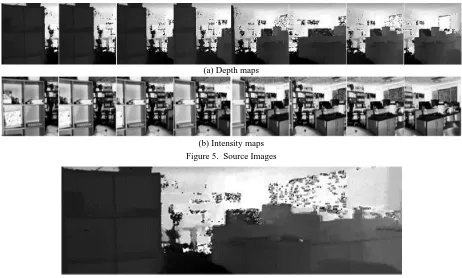
First, we took depth maps by rotating the depth camera clockwise roughly by 10 degrees. The angular difference between the first and the eighth images would be 80 degrees. Through this step, we acquired 8 depth maps and intensity maps of 176 x 144 pixels. Figure 5 shows these maps.
Among 8 depth maps, we constituted 7 depth map pairs. For each depth map pair, we conducted tiepont extraction, 3D similarity transformation estimation. In making depth map mosaic, we calculated the area of mosaic image and resampled each map. Figure 6 shows output of this process. We can visually see that depth map mosaicking was successfully applied.
4.2 Verifying Accuracy
For verifying transformation accuracy, we calculated RMSE of the difference between 3D coordinates of tiepoints in the reference depth map and 3D coordinates of corresponding tiepoints in the pair depth map after applying 3D similarity transformation. Table 3 shows results. We can observe that errors in depth direction were larger that errors in X and Y direction. This is due to the fact that we used noisy depth values over noisy tiepoints. The z coordinates calculated from our method would combine errors in depth values and errors in 2D tiepoint coordinates.
The International Archives of the Photogrammetry, Remote Sensing and Spatial Information Sciences, Volume XLI-B3, 2016 XXIII ISPRS Congress, 12–19 July 2016, Prague, Czech Republic
This contribution has been peer-reviewed.
(a) Depth maps
(b) Intensity maps Figure 5. Source Images
Figure 6. Result images of mosaicking It is also notable that errors were increased as matching pairs
were moving further from the reference image (image number 1). Due to the accumulated effects of noisy tiepoints, we observed this error propagation.
Table 2. RMSE of matching pair’s tiepoint coordinates (X,Y,Z) Matching
pair
RMSE of X(mm)
RMSE of Y (mm)
RMSE of Z (mm) 1 & 2 12.5183 5.8769 19.9858 2 & 3 12.3145 7.8861 19.9046 3 & 4 16.3924 4.4648 23.7226 4 & 5 9.1252 9.7904 23.5761 5 & 6 6.2667 9.3772 23.7884 6 & 7 11.3569 8.1623 26.2264 7 & 8 11.4030 7.6917 24.2967 Average 11.3396 7.6070 23.0715
4.3 Processing Time
We estimated mosaicking time to test the feasibility of real-time processing. Table 4 shows processing time for extracting tiepoints and estimating 3D transformation coefficient.
Table 3. Major steps of processing time (msec) Matching
pair
Extracting Tiepoint
Estimating 3D transformation Coefficients
1 & 2 903.9 538.7
2 & 3 1003.0 639.4
3 & 4 973.4 557.0
4 & 5 969.1 711.7
5 & 6 1129.0 986.7
6 & 7 1066.5 994.4
7 & 8 1225.3 1197.1
It took roughly 1 second for extracting 3D tiepoints from a depth map pair. Time for estimating 3D transformation was from 0.5 second to 1.2 second. For generating a depth map mosaic, it spent 7.9 msec to setting area of mosaic image and 408.6 msec to making depth map. On average, it took roughly 2 seconds for making one depth map mosaic. This processing time was measured on a CPU Core2 Quad Q9550, clock speed 4GHz, RAM 8GB and graphic card geForce 9800GT. For real-time processing, algorithm optimization is required.
5. CONCLUSION
This paper proposes a method of automated mosaicking of multiple 3D point clouds generated from a depth camera. Through the experiments, it is proved that it can be applied for automated mosaicking of multiple 3D point clouds. Our method showed error propasgation problem and was somewhat slow for real-time processing. So, we will study further for handling error propagation problem and for reducing processing time.
REFERENCES
Yehuda, A., Ariel, B., 1998. Mosaicking of Orthorectified Aerial Images. In: Photogrammetric Engineering and Remote Sensing, Vol 64, pp. 115-125.
Edward, R., Tom, D., 2006. Machine Learning for HighSpeed Corner Detection. Computer Vision. In: ECCV 2006, pp. 430-443.
David, G., Lowe, 2004. Distinctive Image Features from Scale-Invariant Keypoints. In: International journal of computer vision, Vol.60, Number 2, pp. 91-110.
The International Archives of the Photogrammetry, Remote Sensing and Spatial Information Sciences, Volume XLI-B3, 2016 XXIII ISPRS Congress, 12–19 July 2016, Prague, Czech Republic
This contribution has been peer-reviewed.