QTRAJECTORIES: IMPROVING THE QUALITY OF OBJECT TRACKING USING
SELF-ORGANIZING CAMERA NETWORKS
Uwe Jaenena, Udo Feuerhakeb, Tobias Klingerc, Daniel Muhlec, Joerg Haehnera, Monika Sesterb, Christian Heipkec
Universitaet Augsburg - Lehrstuhl fuer Organic Computinga
Leibniz Universitaet Hannover - Institut fuer Kartographie und Geoinformatikb Leibniz Universitaet Hannover - Institut fuer Photogrammetrie und GeoInformationc
Appelstrasse 9a, 30167 Hannover, Germany http://www.ikg.uni-hannover.de/index.php?id=696
KEY WORDS:Cooperation, Distributed, Automation, Organization, Pattern, Tracking, Networks, Performance
ABSTRACT:
Previous work in the research field of video surveillance intensively focused on separated aspects of object detection, data association, pattern recognition and system design. In contrast, we propose a holistic approach for object tracking in a self-organizing and dis-tributed smart camera network. Each observation task is represented by a software-agent which improves the tracking performance by collaborative behavior. An object tracking agent detects persons in a video stream and associates them with a trajectory. The pattern recognition agent analyses these trajectories by detecting points of interest within the observation field. These are characterized by a non-deterministic behavior of the moving person. The trajectory points (enriched by the results of the pattern recognition agent) will be used by a configuration agent to align the cameras field of view. We show that this collaboration improves the performance of the observation system by increasing the amount of detected trajectory points by 22%.
1 INTRODUCTION
In recent years video surveillance has become a ubiquitous safety procedure. Today’s surveillance systems, which are in practi-cal use, consist of optipracti-cal sensors which stream image data in a central control room. The streams are analyzed manually by security staff or stored to save it as evidence. With an increas-ing number of them, the manual analysis of video streams and the configuration of the network becomes infeasible. The cur-rent research focuses on fully automated surveillance systems. This paper presents a holistic approach for distributed and self-organizing person tracking in sensor networks. This network con-sists of smart camera nodes. Object observation in such networks essentially consists of three tasks. The object tracking task de-tects objects, associates these with trajectories and so provides consistent object-ids. The pattern recognition analyses the col-lected trajectories. Based on this analysis, typical characteristics about the object movement can be estimated. This prior knowl-edge can be used as input to the configuration task of the sensor network. Each of these tasks is represented by software agents which provide their service to each other. We show that the col-laborative solution improves the performance of the system. Per-formance itself is measured in a quality matrix, which is a bench-mark on how an agent performs his task. Generally each task is equipped with a global quality metric (Qot, Qpr, Qco). The quality measure of the object tracking agent (Qot) is built upon the length of the individual trajectories. The pattern recognition on persons trajectories needs a minimum trajectory length to an-alyze the trajectory and to predict the moving direction with a high confidence level. It is also important to include informa-tion about where an individual has come from, possible target distances, similarities of the current trajectory to existing trajec-tories and what other individuals have done in the same situation before. The probability that an individual reaches a possible tar-get is calculated by a function which contains factors describing the needed information. In this case the quality metric (Qpr) cor-responds to the confidence level. The configuration agent aims at a high number of tracked objects under the constraints of the pattern recognition. This can be interpreted as the sum over the
length of all trajectories as metric (Qco). Therefore the agent estimates the time the object is in its viewing range. Objects which can be tracked together will be handled and tracked as a group. Based on these analyses the agent generates a schedule. Objects which cannot be integrated in the schedule will be offered to neighboring cameras using the results of the pattern recogni-tion. It is evident that the agents’ goals depend on each other. This is also depicted in Fig. 1 below.
Ob ject
Tra cki
ng
Ag en
t
C on
fig ura
tio n Ag
ent
Pattern Recognition Agent
Pattern Recognition Agent Provides
„Predicted Movement Direction“
(x,y,z, timestamp, velocity vector, confidence level)
Object Tracking Agent Provides „Current Trajektories“ (x,y,z, timestamp, velocity
vector, confidence level)
Configuration Agent Provides
„Optimal Camera Alignment“
(pan-, tilt-, zoom-angles)
Figure 1: Circle of collaboration
A holistic measure of the success of the collaboration can be de-fined as the face of a kiviat diagram which axes are dede-fined by the quality metrics of each agent. This paper shows that the collabo-ration will increase the amount of detected trajectory points.
2 SYSTEM DESCRIPTION
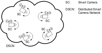
distinguish between three states of evolution. Systems of the first generation are classified by using analogues CCTV tech-niques for image distribution and storage in a single control room. Surveillance of the second generation also called semi-automatic systems use automated visual surveillance by combining com-puter vision and CCTV (Closed Circuit Television) systems. We want to achieve a partial contribution to systems of the third gen-eration, fully automated wide-area surveillance systems. These systems are characterized by distribution of intelligence and also using different collaborative sensor nodes. The considered obser-vation system within this article consists of several pan-tilt-zoom (PTZ) capable smart cameras, see Fig. 2. A smart camera simpli-fied consists of an optical sensor and a computation unit and was first introduced by (Schneidermann, 1975). The smart camera is an automated system. The output of the optical sensor will be processed by the local computation unit, so no image data has to be transferred using communication. The network traffic can be reduced to event- and status-messages. The several observation tasks are represented by software-agents. In this work we regard the object tracking, pattern recognition and the camera alignment as agents.
D
D D
D
D
SC
SC
SC SC
SC
DSCN
SC: Smart Camera
DSCN: Distributed Smart Camera Network
Figure 2: System overview
3 STATE OF THE ART
In this paper we present a holistic approach for object tracking, pattern recognition on trajectories and reconfiguration of camera networks. The separated components have been subject of nu-merous investigations. The design of a holistic system has been neglected several years, which was also mentioned by (Velastin and Remagnino, 2006). In order to design an automated tracking system, it is possible to access many publications which address special topics of the object tracking research field. (Everts et al., 2007) presented a system with multiple calibrated PTZ cameras which are used to track objects. The tracking and calibration re-sults are combined, whereby the cameras can pass trackable ob-jects to each other. Furthermore a real-time prototype system, consisting of two cameras, is introduced. The evaluation focuses on image processing techniques and shows that real-time tracking is possible with multiple PTZ cameras. (Ukita, 2005) describe a system consisting of smart-cameras so called Active Vision Agents which can track objects cooperatively. The focus is on multiple-view tracking rather than on scheduling of object track-ing tasks beyond a wide area smart camera network. In (Quar-itsch et al., 2007), the authors describe a method for object track-ing with embedded smart cameras, i.e. the cameras have been im-plemented in specialized hardware. They pursued an agent-based design method. A tracking agent is responsible for the detection, identification and tracking of objects over time in a video stream of a single camera. These agents migrate through the network to follow the corresponding object. Using non-PTZ capable cam-eras, migration areas are defined within the image which causes a transfer of the agent to a corresponding neighboring camera if an object enters this field. The focus is on a hardware-based implementation and was evaluated on three advanced smart cam-eras. (Monari and Kroschel, 2010) show a task-oriented sensor
selection algorithm approach for multi-camera object tracking us-ing non-PTZ capable cameras. The algorithm aims at a highly reduced network and processor load by disabling unnecessary nodes. Our goal is to use the results of the pattern recognition on the trajectory data to align the cameras field-of-view (FoV) to optimally utilize the limited camera resources.
4 OBJECT TRACKING
The purpose of the object tracking agent is to gather trajectories, i.e. the locations (X,Y,Z,t) of people passing the scene sampled over a sequence of images in accordance with a motion model. This agent provides the input to the pattern recognition agent (see Fig. 1). The pattern recognition agent requires preferably long trajectories to provide the configuration agent with proper prior knowledge. We scan each image with a sliding window based pedestrian detector and use the responses as evidence for the pres-ence of people. From literature one can conclude that variants of the HOG / SVM framework perform very well under our viewing conditions (Enzweiler and Gavrila, 2009), i.e. pedestrians ap-pear in a range of approx. 50-200 pixel vertical elongation. For pedestrian detection we thus follow (Dalal and Triggs, 2005), and classify Histograms of Oriented Gradients (HOG) with a support vector machine as either people or non-people. In order to sup-press false alarms, a new target is only initialised, if the detection coincides with what is declared as foreground, i.e. if the centre pixel of the region classified as human belongs to the foreground. Foreground regions are found by applying a Gaussian Mixture Model as in (Stauffer and Grimson, 1999). For each frame the RGB colour space is transformed into HSV representation and the hue image is masked with the background region. For ini-tialisation a target is described by the static representation of its hue histogram as observed at the moment of detection. In order to evaluate only pixels that belong to the target, we calculate this histogram by using exactly those pixel inside the bounding box indicated by the detector that belong to the foreground region. For tracking, correspondences between a target’s trajectory and a candidate region of the current masked hue image are estab-lished with the candidate that best matches the target template. The matches are found using the mean shift algorithm as in (Co-maniciu et al., 2003). The footprint of the bounding ellipse that best explains the target’s state is appended to the trajectory. Fi-nally, we associate a motion model to each target in terms of a linear Kalman Filter, which smoothes the trajectory into a more plausible shape and can be used for gating the search space for recovering objects after occlusions in future work. A schematic of the workflow for detection and tracking is depicted in Fig. 3. In our testing scenario, the atrium of our university, people ap-pear mostly isolated, as depicted in Fig. 4. The yellow grid in the graphic is equally spaced with 1m in world coordinates. The trajectory of the tracked person is shown as a red line (raw de-tection) and a green line (filtered) respectively. The green box indicates the result of the HOG detector and the ellipse the out-put of the mean shift method. If an object completely leaves the visible scope of observation and re-enters the scene, the tracker does not recover this object but initialises it as a new target. Each trajectory is appended with a quality measureQotiwhich can be accounted by the further tasks. We define a flagQoti ∈[0,1]that indicates if the trajectory approaches the image border where the mean shift tracker might potentially fail due to partial visibility of the people.
5 PATTERN RECOGNITION
ob-People Detection
Coincidence? Target candidate
Yet exists?
Mean Shift Tracking Find Match?
Target representation - state/trajectory - motion model - appearance model
Im
ag
e
S
tr
e
am
Create Update
Finish Foreground
Detection
RGB to HSV conversion
yes yes
no
no no
yes
Figure 3: Workflow Detection and Tracking
Figure 4: Tracking a single person in the atrium sequence.
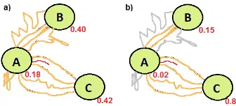
jectives, which depend on the overall system goal, this analysis contains the prediction of movements to estimate future positions of objects. This prediction knowledge is demanded by the given system structure. Since we are using few smart cameras with a limited FoV, we are not able to observe the entire scene com-pletely. There are ’dark’ gaps, in which moving objects may dis-appear from tracking. Due to the fact that the configuration agent, which receives the results of the pattern recognition agent, aims to avoid gaps within tracks, it requires knowledge, how to adjust the cameras optimally. This knowledge is gained by the predic-tion objective. This objective also contains the evaluapredic-tion of the predictions with the help of a quality metricQpr. The latter is derived by the significance and the reliability of the calculated values that indicate the most possible future position. The pat-tern recognition is also more efficient, if the basis of the analysis, namely the trajectories, are more complete and reliable as well. There are various possibilities to predict movements. Often and in the simplest case a future locationlt+∆tis calculated by a lin-ear relationship of the current locationltand velocity vectorvt likelt+∆t = lt+∆tvt. In most cases objects do not behave like this. Their movements are initiated or influenced by many factors. For instance, those factors are described by a social force model in (Helbing and Molnar, 1995). Furthermore, since we are motivated by implementing a camera tracking system, we need to use a prediction method which is able to operate at runtime. Considering those features we use an approach containing sev-eral consecutive algorithms. The first one, which is described in detail in (Feuerhake et al., 2011), creates and updates the ba-sis for our prediction algorithm. The result of this first step is a graph structure (see Fig. 5), which is incrementally built up by extracted interesting places and a segmentation of trajectories, which clusters trajectory segments connecting the same start and end places. The resulting graph is an input for the second step. In this step the next possible destinations and the corresponding probabilities of moving objects are calculated. The second step consists of the prediction algorithm. Statements about possible paths of an object are made with the help of the graph at every time step. Each of those statements is quantified by a probability value. The calculation of such a value always refers to the cur-rent position of the object and all leaving edges from the last it has reached. First of all, statistics of all outgoing trajectories can be set up to yield probability values of a possible decision.
How-ever, a decision will also depend on additional factors (see Fig. 6), e.g.: the way selection other objects have taken before (a), the distance to possible destinations (b), the similarities concerning the shape of the current to other way segments (c) as well as the already passed way (d).
Figure 5: Using a places extraction algorithm for creating the graph as basis for the prediction algorithm
Figure 6: The probability depends on four factors: (a) preferred destination of other individuals, (b) distance to possible destina-tions, (c) similarities concerning shape and parameters of the cur-rent to other way segments, (d) already passed places.
We use the example in Fig. 6(c) to describe the creation of the probability values of the red object trajectory, which has left the place A. The first factor can be derived by the relative frequency the edge of the graph was used, which connects the last node (A) and the possible destination nodeX=A, B, C. So letx1, .., xn be the usage counts of the edges leaving nodeAandx1 be the count of the edge connectingA and X. Then the probability valuePowof destinationXis calculated by
Pow(X) = x
1 n
P
i=1
xi
(1)
It does not depend on the individual’s current position and re-mains the same until another place is entered. The next factor compares distances to possible destinations. LetP be the cur-rent position of an individual. The relationship between distances
d(P, .)and probabilityPdof nodeBcan be described by
Pd(X) = 1−
d(P, X)
n
P
i=1
d(P, Xi)
(2)
For considering the shape of the way an individual has passed since the last place the Hausdorff distances between the segment bundles, which are already stored in the edges of the graph, and the current segment are calculated. Lets1, .., snbe the segment bundles leading accordingly to the destination nodes,cthe cur-rent segment anddh(., .)the Hausdorff distance. Then the prob-abilityPcw(X)an individual is moving toXis calculated by
Pcw(X) = 1− dh(c, s 1) n
P
i=1
dh(c, si)
The last factor deals with the history of visited places. The prob-ability is described by the relative frequency of a given sequence in a subset of all sequences. LetS1, .., Snbe the corresponding sequences ending at the given destinations and containing a given subsequence of nodes (previous node, current node). This leads to the following relationship
Ppw(X) =
S1
n
P
i=1
Si
(4)
Since the introduced factors give independent hints for the next probable destination, we combine them by summing them up. At the same time we weight them. Those weights are used to normalize the probability value and to handle different scenarios, where the relevance of each factor differs. For instance, given a scenario, it is known a priori that the distances to possible targets play a minor role, the relevance of the distance factorPdcan be reduced by decreasing the its weightwd. In general, if there is no a priori knowledge, the factors should be equally weighted. An auto-determination of the optimal weight setting is planned. Compared to the example shown in Fig.7(a) the overall proba-bilityP(X)for the next visited place including the components described above is
P(X) =ωow·Pow(X) +ωd·Pd(X)
+ωcw·Pcw(X) +ωpw·Ppw(X)
(5)
with
ωow+ωd+ωcw+ωpw= 1 (6)
As most of the factors heavily depend on the completeness and the quality measurementQotof the tracking agent to filter out bad tracks, the results of the pattern recognition agent also depend on these features. So prediction statements of the most probable des-tination of an object become more significant and reliable, which means that the qualityQprincreases as well.
Figure 7: Example for the different results of the destination pre-diction of an object in the presence of bad tracks (red: current seg-ment, orange: considered segments, grey: neglected segments)
6 CAMERA ALIGNMENT FOR OBJECT TRACKING
The configuration agent is responsible to align the FoV to op-timally exploit the limited sensor resources. Such a scenario is depicted in Fig. 8. The moving objects (squares) are observed by smart cameras (triangles). Basically, our solution is subjected to the following constraints: We have a limited number of smart cameras. The path of individual objects through the network is unknown. The goal of the configuration agent is a reasonable tracking of individual objects and to achieve the maximum sys-tem performance with respect to the constraints of a distributed system. This leads to the question how ”system performance” can be defined. The configuration agent tries to increase the amount of trajectory points (tp) which are detected by the tracking agent for each object (objID) for each time step (t). A formal descrip-tion is given by equadescrip-tion 7.
1
4 7 11
1
2
3 4
4 5
6 7
8
9 10
11 12
13
14 15
10
Figure 8: Coverage Agent
In order to consider the priority of an object in security scenarios (tp) can be weighted with a parameter describing the priority.
maxn X
objID
X
t
tp(objID, t)o (7)
tp(objID, t) =
(
1, ifpos(objID)∈F oV
0, otherwise (8)
The tracking agent provides object positions in world-coordinates (X,Y,Z,t) with a unique object-ID. The approach is divided into the following steps.
1. Analyzing the time detected objects will remain in the range of work of the smart camera (SC)
2. Grouping objects which can be tracked simultaneously 3. Inserting these groups into the scheduler
4. Objects which leave the viewing range of the SC will be transfered to neighboring cameras
During the first step the time which a detected object remains in the viewing range of the smart camera is estimated. For this task the velocity of the object is predicted based on linear regression of the detected trajectory points. The observation time is the time duration an object is expected to move through the viewing range of the smart camera. This is depicted in Fig. 9(a). In the second step objects which can be tracked at the same time are grouped (Fig. 9(b)). For the calculation of the tracking time as grouped targets we introduce a heuristic. To avoid an analysis whether all objects are included in the reconfigurable FoV, the footprint of the FoV are approximated by a working-circle (WC). On the left of Fig. 9(b) a pessimistic estimation of the WC diameter is depicted. An estimation based on the in-circle of the footprint is sufficient. On the right of Fig. 9(b), object movements are shown in a space-time diagram. For illustrative purposes, the objects are depicted to move in a two-dimensional space (x/y-plane). As long as the distance of two tracked objects is less than the diameter of the working-circle, the objects can be tracked together. This 2-tuple can be combined to a 3-tuple, see Fig. 9(c). Each of those three objects has to fit in the WC during the observation time. This is fulfilled as long as the distance between each pair of these three objects is less than or equal 3
2√
v
tEnter
tLeaving
(a) Estimation
of the maximum
observation time for a single target (red square) based on the viewing range and the velocity~v.
x
y t
t0
t1
obj1 obj2 ØWC
FoV Footprint
(b) Estimation of the observation time for a 2-tuple of targets. The footprint of the FoV can be approximated by a working circle (WC) which is depicted on the left. It shows a pessimistic estima-tion of the WC diameter, an in-circle of the foot-print is a sufficient approximation. Two objects can be tracked as a group as long as the distance is less than or equal the diameter of the WC as de-picted on the right.
obj1
obj2 obj3
ØWC
ØWC 2 3
3
(c) A 3-tuple of objects can be tracked as a group if the distance between them is less than or equal 2√3
3. This is a pessimistic
estimation.
obj1
obj2 obj3
obj4
(d) A k-tuple can be tracked as a group if all objects fit into the WC. For this task any 2-tuple combina-tions of the k-tuple includ-ing objects must be track-able as a group.
Figure 9: Calculation of k-tuple of trackable objects.
of any of the 2-tuple. Based on these predictions a scheduling graph as depicted in Fig. 10 is constructed. The configuration agent aligns the FoV according to this graph. The goal of the tracking agent is to maximize the number of detected trajectory points (Eq. 7). A simple heuristic to achieve this goal is to se-lect the scheduling graph entry with the most objects. In Fig. 10 the configuration agent follows object 1, 2, 3 and 4 at time step
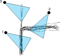
tcurrent. If an object can no longer be tracked by a SC, this object will be offered to neighboring cameras. Based on the analysis of the pattern recognition agent a value is assigned to each trajec-tory, expressing the probability with which point of interest will be visited next. Based on this probability values a corresponding neighboring camera is selected. In Fig. 11 exemplary trajecto-ries and three cameras are depicted. It is obvious that an object leaving the observation range of camera1should be offered to camera2because of the higher probability of re-detection.
1 Objects
2
t 1, 2, 3
1, 2, 3, 4
tcurrent
Figure 10: This scheduling graph exemplarily is showing in which time interval objects and groups of objects can be tracked.
1
2 3
Figure 11: This figure shows exemplarily trajectories and three cameras. If an object leaves the observation range of camera1it will be re-detected with a higher probability in the viewing range of camera2than in the FoV of camera3.
7 RESULTS AND DISCUSSION
For the evaluation of the described approach we recorded a video-stream in the atrium of our university. The camera was positioned at a height of approximately 7m. In the first step the video has been analyzed by the object tracking agent. In the next step these trajectories have been analyzed by the pattern recognition agent. Each trajectory point was enriched with a list of possible destina-tions and a corresponding probability/confidence by the pattern recognition agent. The configuration agent was analyzed using the multi-agent simulation toolkit MASON (Luke et al., 2004). Using simulation gives us the possibility to repeat the evaluation under various conditions with the same ground truth data of the object tracking, and pattern recognition agent.
7.1 Results of the Object Tracking Agent
For the general case of people appearing isolated in the image, we achieve satisfying results with our tracking strategy. When two or more targets overlap in the image domain, the appearance model supports the re-association to the temporarily occluded right tar-get (see Fig. 12) but drawbacks in the geometric accuracy of the trajectories might be encountered during occlusions. Upon visual inspection the geometric accuracy of the trajectories is not worse than half a meter, which mainly results from the rough approx-imation of the target position by the ellipse. We plan to over-come such drawbacks by incorporating detection based strategies rather than template tracking in future work and analyzing pat-terns of motion for bridging local occlusions. The strategy for data association can be improved by replacing the static appear-ance model with an adaptive one. Applied to a target and updated over time, such a learning step is expected to improve recogni-tion by generalizing to a broader variety of object appearances while discriminating against other targets. The quality measure of the individual trajectories,Qoti, is exchangeable and will be replaced with a more sophisticated measure of quality, that ac-counts for the particular tracker, in future work.
7.2 Results of the Pattern Recognition Agent
Figure 12: Tracking multiple persons with overlapping viewing ranges. Note the person in the red dress, initialized in the left image is kept tracking in the right image after partial occlusion.
Case 1 Case 2
R(total) 18.02% 43.89%
R(Pow) 17.69% 36.87%
R(Pd) 18.97% 43.53%
R(Pcw) 18.72% 39.26%
R(Ppw) 15.02% 40.01%
Table 1: Percentage of correct predictions for different test cases.
four scenarios show the correctness values for each prediction
(R = correctpredictions/totalpredictions)factor
individu-ally. In each of these scenarios an increase of about 20-25% is recognizable.
7.3 Results of the Configuration Agent
The trajectory-data (enriched by the results of the pattern recog-nition agent) was used as input of the multi-agent simulation toolkit. During the simulation we placed four smart cameras in the observation area, see Fig. 13. We repeated the simulation two times. During the first evaluation the configuration agents have no collaborative behavior. The neighboring cameras were not no-tified about possible targets in their observation area. In the next evaluation the possible destination points of the pattern recogni-tion agent were used to notify the cameras near the predicted des-tination point. These cameras aligned their FOV to the expected target. During the first evaluation the cameras were capable to record 2177 trajectory points. Using collaboration between the agents increases the number of trajectory points to 2666. As de-scribed in equation 7 the number of detected trajectory points is the goal to be optimized. Using collaborative behavior increases the number of trajectory points significantly by 22%.
Figure 13: Screenshot of the MASON simulation toolkit. It de-picts the used camera setting as it was in use during the evalua-tion. The black dots mark the position of the points of interest as result of the pattern recognition agent.
8 CONCLUSIONS AND FUTURE WORK
In this paper we presented a holistic approach for object tracking. We introduced three agent types which use collaboration to im-prove their individual skills. An object tracking agent is responsi-ble to calculate trajectory points which are analyzed by a pattern recognition agent to find points of interest within the observa-tion field. These data are then used to align the cameras field of view by the configuration agent. Neighboring cameras can notify each other about approaching objects. The evaluation shows an increasing of detected trajectory points of 22%. In future work we want to integrate the software agents into smart cameras to evaluate the real-time capability.
ACKNOWLEDGEMENTS
We gratefully acknowledge the financial support by the German Research Foundation (DFG) for the project QTrajectories (DFG grant IDs: HA 5480/2-1, HE 1822/24-1, SE 645/7-1).
REFERENCES
Comaniciu, D., Ramesh, V. and Meer, P., 2003. Kernel-based object tracking. Pattern Analysis and Machine Intelligence, IEEE Transactions on 25(5), pp. 564 – 577.
Dalal, N. and Triggs, B., 2005. Histograms of oriented gradients for human detection. In: Computer Vision and Pattern Recogni-tion, 2005. CVPR 2005. IEEE Computer Society Conference on, Vol. 1, pp. 886 –893 vol. 1.
Enzweiler, M. and Gavrila, D., 2009. Monocular pedestrian de-tection: Survey and experiments. Pattern Analysis and Machine Intelligence, IEEE Transactions on 31(12), pp. 2179 –2195.
Everts, I., Sebe, N. and Jones, G., 2007. Cooperative object track-ing with multiple ptz cameras. In: Image Analysis and Process-ing, 2007. ICIAP 2007. 14th Int. Conf. on, pp. 323 –330.
Feuerhake, U., Kuntzsch, C. and Sester, M., 2011. Finding inter-esting places and characteristic patterns in spatiotemporal trajec-tories. In: 8th LBS Symposium 2011, pp. 4–21.
Helbing, D. and Molnar, P., 1995. Social force model for pedes-trian dynamics. Physical review E 51(5), pp. 4282.
Luke, S., Cioffi-revilla, C., Panait, L. and Sullivan, K., 2004. Mason: A new multi-agent simulation toolkit. In: University of Michigan.
Monari, E. and Kroschel, K., 2010. Task-oriented object tracking in large distributed camera networks. In: Advanced Video and Signal Based Surveillance (AVSS), 2010 Seventh IEEE Interna-tional Conference on, pp. 40 –47.
Quaritsch, M., Kreuzthaler, M., Rinner, B., Bischof, H. and Strobl, B., 2007. Autonomous multicamera tracking on embed-ded smart cameras. EURASIP J. Emb. Syst. 2007, pp. 35–35.
Schneidermann, R., 1975. Smart cameras clicking with electronic functions. Electronics 48, pp. 74–81.
Stauffer, C. and Grimson, W., 1999. Adaptive background mix-ture models for real-time tracking. In: Computer Vision and Pat-tern Recognition, 1999. IEEE Computer Society Conference on., Vol. 2, pp. 2 vol. (xxiii+637+663).
Ukita, N., 2005. Real-time cooperative multi-target tracking by dense communication among active vision agents. In: Intelligent Agent Technology, IEEE/WIC/ACM Int. Conf., pp. 664 – 671.