by Lee Ambrosius
AutoCAD
®
2008
3D Modeling
Workbook
FOR
by Lee Ambrosius
AutoCAD
®
2008
3D Modeling
Workbook
FOR
111 River Street Hoboken, NJ 07030-5774
www.wiley.com
Copyright © 2007 by Wiley Publishing, Inc., Indianapolis, Indiana Published by Wiley Publishing, Inc., Indianapolis, Indiana Published simultaneously in Canada
No part of this publication may be reproduced, stored in a retrieval system or transmitted in any form or by any means, electronic, mechanical, photocopying, recording, scanning or otherwise, except as permitted under Sections 107 or 108 of the 1976 United States Copyright Act, without either the prior written permission of the Publisher, or authorization through payment of the appropriate per-copy fee to the Copyright Clearance Center, 222 Rosewood Drive, Danvers, MA 01923, (978) 750-8400, fax (978) 646-8600. Requests to the Publisher for permission should be addressed to the Legal Department, Wiley Publishing, Inc., 10475 Crosspoint Blvd., Indianapolis, IN 46256, (317) 572-3447, fax (317) 572-4355, or online at http://www.wiley.com/go/permissions.
Trademarks:Wiley, the Wiley Publishing logo, For Dummies, the Dummies Man logo, A Reference for the Rest of Us!, The Dummies Way, Dummies Daily, The Fun and Easy Way, Dummies.com, and related trade dress are trademarks or registered trademarks of John Wiley & Sons, Inc. and/or its affiliates in the United States and other countries, and may not be used without written permission. All other trademarks are the property of their respective owners. Wiley Publishing, Inc., is not associated with any product or vendor mentioned in this book.
Autodesk and AutoCAD are registered trademarks of Autodesk, Inc., in the U.S.A. and certain other countries. Certain con-tent, including trial software, provided courtesy Autodesk, Inc., © 2007. All rights reserved.
LIMIT OF LIABILITY/DISCLAIMER OF WARRANTY: THE PUBLISHER AND THE AUTHOR MAKE NO REPRESENTATIONS OR WARRANTIES WITH RESPECT TO THE ACCURACY OR COMPLETENESS OF THE CONTENTS OF THIS WORK AND SPECIFICALLY DISCLAIM ALL WARRANTIES, INCLUDING WITHOUT LIMITATION WARRANTIES OF FITNESS FOR A PAR-TICULAR PURPOSE. NO WARRANTY MAY BE CREATED OR EXTENDED BY SALES OR PROMOTIONAL MATERIALS. THE ADVICE AND STRATEGIES CONTAINED HEREIN MAY NOT BE SUITABLE FOR EVERY SITUATION. THIS WORK IS SOLD WITH THE UNDERSTANDING THAT THE PUBLISHER IS NOT ENGAGED IN RENDERING LEGAL, ACCOUNTING, OR OTHER PROFESSIONAL SERVICES. IF PROFESSIONAL ASSISTANCE IS REQUIRED, THE SERVICES OF A COMPETENT PROFESSIONAL PERSON SHOULD BE SOUGHT. NEITHER THE PUBLISHER NOR THE AUTHOR SHALL BE LIABLE FOR DAMAGES ARISING HEREFROM. THE FACT THAT AN ORGANIZATION OR WEBSITE IS REFERRED TO IN THIS WORK AS A CITATION AND/OR A POTENTIAL SOURCE OF FURTHER INFORMATION DOES NOT MEAN THAT THE AUTHOR OR THE PUBLISHER ENDORSES THE INFORMATION THE ORGANIZATION OR WEBSITE MAY PROVIDE OR RECOMMEN-DATIONS IT MAY MAKE. FURTHER, READERS SHOULD BE AWARE THAT INTERNET WEBSITES LISTED IN THIS WORK MAY HAVE CHANGED OR DISAPPEARED BETWEEN WHEN THIS WORK WAS WRITTEN AND WHEN IT IS READ.
For general information on our other products and services, please contact our Customer Care Department within the U.S. at 800-762-2974, outside the U.S. at 317-572-3993, or fax 317-572-4002.
For technical support, please visit www.wiley.com/techsupport.
Wiley also publishes its books in a variety of electronic formats. Some content that appears in print may not be available in electronic books.
Library of Congress Control Number: 2007926005 ISBN: 978-0-470-09763-2
About the Author
Lee Ambrosiusis a former resident of a cubicle community, which he resided in for about 8 years until deciding to go into business for himself. In 2005, Lee decided to venture off into the CAD industry as an independent consultant for HyperPics, LLC in De Pere, Wisconsin, and on the Web at www.hyperpics.com. He has been using AutoCAD since 1994 when he was first exposed to Release 12 for DOS, and has been customizing and programming AutoCAD since 1996. Lee has been an AutoCAD consultant and trainer for over a decade, and is both an Autodesk Authorized Author and an Autodesk Authorized Developer.
Over the last decade, Lee has authored a variety of works that include articles for CAD maga-zines, white papers for Autodesk, and has been a contributing author on a few occasions for AutoCAD books. Lee is a co-author of AutoCAD and AutoCAD LT All-in-One Desk Reference For Dummies. He has done technical editing for the three most recent editions of AutoCAD For Dummies, and the four most recent editions of AutoCAD and AutoCAD LT Bible. AutoCAD 2008 3D Modeling Workbook For Dummiesis his first solo venture as a book author.
Dedication
To my parents, for believing in me and being there when I needed them the most, especially when helping a broke college student purchase his first computer those many years ago (even though you thought it wasn’t the best thing to do at the time).
Author’s Acknowledgments
I have to give a special thanks to Kristina, my wife, and my three kids, Isaac, Amber, and Chloe, for letting me put in the long hours needed to complete this book. Thanks to all the great folks at Wiley for being supportive through this entire project and giving me this great opportunity to write this book.
Some of the people who helped bring this book to market include the following:
Acquisitions, Editorial, and Media Development
Project Editor:Rebecca Senninger
Acquisitions Editor:Kyle Looper
Copy Editor:Virginia Sanders
Technical Editor:Mark Douglas
Editorial Manager:Leah Cameron
Media Development and Quality Assurance:
Josh Frank
Media Development Coordinator:Jenny Swisher
Media Project Supervisor:Laura Moss-Hollister
Editorial Assistant:Amanda Foxworth
Sr. Editorial Assistant:Cherie Case
Cartoons:Rich Tennant (www.the5thwave.com)
Composition Services
Project Coordinator:Adrienne Martinez
Layout and Graphics:Carrie A. Foster, Denny Hager, Joyce Haughey, Stephanie D. Jumper
Proofreaders: Christy Pingleton, Kathy Simpson
Indexer: Aptara
Anniversary Logo Design:Richard Pacifico
Special Help: Mark Hechel of MasterGraphics, Inc.
Publishing and Editorial for Technology Dummies
Richard Swadley,Vice President and Executive Group Publisher
Andy Cummings,Vice President and Publisher
Mary Bednarek,Executive Acquisitions Director
Mary C. Corder,Editorial Director
Publishing for Consumer Dummies
Diane Graves Steele,Vice President and Publisher
Joyce Pepple,Acquisitions Director
Composition Services
Gerry Fahey,Vice President of Production Services
Contents at a Glance
Introduction...1
Part I: Introducing AutoCAD ...5
Chapter 1: AutoCAD and the User Interface ...7
Chapter 2: Working with Drawing Files ...25
Chapter 3: Customizing Your Work Environment ...43
Part II: Going from 2D to 3D...59
Chapter 4: Transitioning from 2D to 3D...61
Chapter 5: Viewing a 3D Model...79
Chapter 6: Taking the Plunge into 3D ...107
Chapter 7: Additional Exercises: Making the Transition...133
Part III: 3D Modeling — Solid Modeling ...139
Chapter 8: Modeling with Solids...141
Chapter 9: Modifying and Analyzing Solids ...163
Chapter 10: Creating Section and Auxiliary Views from Models...185
Chapter 11: Additional Exercises: Modeling with Solids...197
Part IV: 3D Modeling — Surfaces...205
Chapter 12: Modeling with Surfaces ...207
Chapter 13: Complex Surface Modeling ...223
Chapter 14: Modifying Surfaces...235
Chapter 15: Additional Exercises: Modeling with Surfaces ...245
Part V: Visualizing the Design ...255
Chapter 16: Lighting...257
Chapter 17: Materials...273
Chapter 18: Rendering and Animating...287
Chapter 19: Additional Exercises: Visualizing the Design...299
Part VI: Model Interchange ...305
Chapter 20: Plotting to a Hardcopy or an Electronic File...307
Chapter 21: Importing and Exporting 3D Models...321
Part VII: The Part of Tens...329
Chapter 22: More than Ten New Features in AutoCAD 2008...331
Chapter 23: More than Ten Software and Professional Design Resources ...341
Appendix A: Glossary...345
Appendix B: About the DVD ...347
Table of Contents
Introduction ...1
Part I: Introducing AutoCAD...5
Chapter 1: AutoCAD and the User Interface ...7
Launching AutoCAD...7
Navigating the User Interface ...9
Drawing window ...10
Canceling the current command ...20
Dynamic input...21
Dialog boxes...21
Sending an S.O.S. to AutoCAD ...22
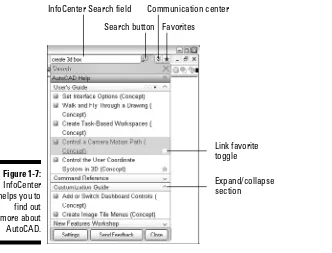
Online help ...22
InfoCenter...22
Turning to the World Wide Web ...24
Answers to Practice Opportunities ...24
Chapter 2: Working with Drawing Files ...25
Creating a New Drawing ...25
Drawing templates ...26
Attaching a digital signature ...34
Closing Drawings...36
Archiving and Backing Up Drawings ...37
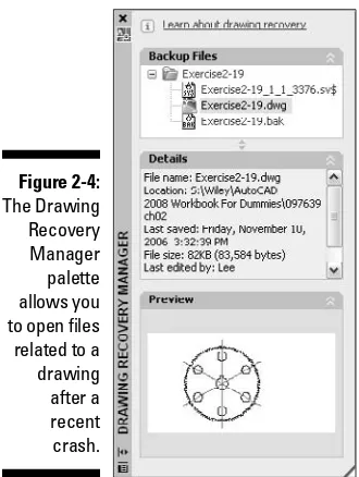
Recovering a Drawing...39
Answers to Practice Opportunities ...42
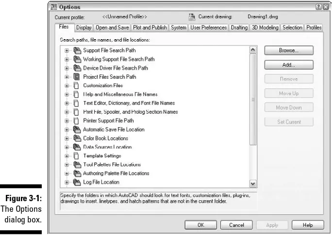
Chapter 3: Customizing Your Work Environment ...43
Using Workspaces ...53
Workspace settings ...54
Customizing AutoCAD and Its User Interface...56
Customizing the user interface...56
Other methods of customizing AutoCAD ...57
Answers to Practice Opportunities ...58
Part II: Going from 2D to 3D ...59
Chapter 4: Transitioning from 2D to 3D ...61
3D Modeling Types Available in AutoCAD ...61
Wireframe model ...61
Surface model ...62
Solid model...62
Going Above the Plane ...63
Entering coordinate values at the command prompt...63
Object snaps ...66
Object snap tracking...68
Point filters...69
Elevating (not levitating) objects ...70
Working with the Coordinate Systems ...70
Understanding the coordinate systems ...71
Getting your bearings from the UCS icon ...71
Customizing the display of the UCS icon ...73
Modifying the UCS ...75
Manipulating the UCS dynamically ...76
Answers to Practice Opportunities ...77
Chapter 5: Viewing a 3D Model ...79
Establishing the Point of View...80
Orthogonal viewpoints ...80
Isometric viewpoints ...80
Using the Viewpoint Presets dialog box...81
Accessing the tripod and compass to find your way ...82
Standard Viewing Mechanics...83
Zooming and panning ...83
Orbiting...85
Looking at a model from two different ways ...87
Advanced Viewing Mechanics...88
Configuring Fly and Walk...89
Navigating with Fly and Walk ...89
Setting the Stage: Cameras and Backgrounds ...91
Named views ...92
Cameras ...94
Backgrounds ...96
Giving Your 3D Models Style (Fashion Tips Not Included)...98
Controlling the Display Quality of 3D Solids ...102
Answers to Practice Opportunities ...105
Chapter 6: Taking the Plunge into 3D ...107
Getting Started: Creating Your First 3D Model ...107
Grid and snap...108
Limits ...110
Blurring the Lines between 2D and 3D ...113
3D polyline ...113
Helix ...114
Making 3D objects out of 2D objects ...116
Modeling with Regions ...119
Creating regions...119
Modifying regions...120
Getting information from a region...122
Modifying 3D Objects ...123
3D Move ...124
3D Rotate ...125
3D Align and Align ...126
Mirror 3D ...128
3D Array...129
Answers to Practice Opportunities ...131
Chapter 7: Additional Exercises: Making the Transition ...133
Navigating a 3D Model...133
Taking a 2D Drawing and Creating a 3D Part ...135
Part III: 3D Modeling — Solid Modeling...139
Chapter 8: Modeling with Solids ...141
Working with 3D Solids...141
Primitive solids...141
Complex solids ...142
Solids that Follow the Straight (And Narrow) ...143
Box ...143
Nothing Complex about These Solids ...153
Add some of this and remove a little of that ...153
As the model revolves ...157
Sweeping...158
Lofting around ...159
Converting objects to 3D solids ...161
Answers to Practice Opportunities ...162
Chapter 9: Modifying and Analyzing Solids...163
Modifying 3D Solids ...163
Properties palette...164
Grip editing ...165
Selecting a subobject ...167
Working with the history of a 3D solid ...170
Filleting and chamfering ...171
Slicing and dicing 3D solids ...173
Solid editing ...175
ix
Branding (imprinting) your 3D solids...179
You don’t have to get pushy ...180
Exploding solids ...181
Putting Your Model under the Microscope ...181
Getting information from your model...181
Analyzing your model ...182
Answers to Practice Opportunities ...183
Chapter 10: Creating Section and Auxiliary Views from Models...185
Creating Section and Auxiliary Views...185
Ready, set, section...185
Viewing, drawing, and profiling solids...190
Flattening a Model...194
Answers to Practice Opportunities ...196
Chapter 11: Additional Exercises: Modeling with Solids ...197
Modeling with Primitive and Complex 3D Solids ...197
Modifying a 3D Solid ...201
Part IV: 3D Modeling — Surfaces ...205
Chapter 12: Modeling with Surfaces ...207
Working with Surfaces ...207
Primitive surfaces ...208
Complex surfaces ...208
Controlling the smoothness of a surface ...209
Putting the Face in Surface ...210
Meshes with Straight Edges...211
Planar Surfaces and Surface Objects...220
Planar surface ...221
Complex surface objects ...221
Answers to Practice Opportunities ...222
Chapter 13: Complex Surface Modeling...223
Creating Complex 3D Meshes...223
Irregular-shaped 3D meshes ...223
Revolved meshes...227
Tabulating meshes ...228
One mesh to rule them all...229
Edgy meshes ...230
Chapter 14: Modifying Surfaces...235
Answers to Practice Opportunities ...244
Chapter 15: Additional Exercises: Modeling with Surfaces ...245
Modeling with Meshes...245
Modeling with Surfaces ...249
Part V: Visualizing the Design...255
Chapter 16: Lighting...257
Using Predefined Lights from Tool Palettes ...266
Modifying Lights...266
Global Lighting ...269
Turning Old into New ...271
Answers to Practice Opportunities ...271
Chapter 17: Materials...273
Creating and Modifying Materials...273
Common material properties...275
Maps...276
Previewing materials and maps...278
Scaling, Tiling, and Offsetting Materials...278
Accessing Libraries of Materials ...280
Attaching and Removing Materials...281
Adjusting Materials...284
Converting Old Materials ...286
Answers to Practice Opportunities ...286
Chapter 18: Rendering and Animating ...287
Rendering Your 3D Model ...287
Cropping before a render ...288
Setting Your Model in Motion...296
Answers to Practice Opportunities ...298
Chapter 19: Additional Exercises: Visualizing the Design...299
Lighting the Way...299
Creating and Attaching Materials ...301
Rendering the Model ...303
Part VI: Model Interchange...305
Chapter 20: Plotting to a Hardcopy or an Electronic File ...307
Plotters and Plot Styles ...307
Plotters ...307
Plot styles ...309
Laying Out Models ...309
Layouts ...310
Floating viewports...312
Plotting and Publishing ...314
Plotting ...314
Publishing...316
Publishing Your Models to the Web...317
Answers to Practice Opportunities ...319
Chapter 21: Importing and Exporting 3D Models ...321
Exchanging 3D Models ...321
Vector file formats ...321
Raster file formats ...324
File Translators...325
Harnessing 3D Models in Non-CAD Applications...326
Part VII: The Part of Tens ...329
Chapter 22: More than Ten New Features in AutoCAD 2008...331
Chapter 23: More than Ten Software and Professional Design Resources...341
Appendix A: Glossary ...345
Appendix B: About the DVD ...347
Table of Exercises
Chapter 1: AutoCAD and the User Interface
Exercise 1-1: Launching AutoCAD ...7
Exercise 1-2: Customizing a Desktop Shortcut with Command Line Switches ...9
Exercise 1-3: Navigating the Drawing Window ...11
Exercise 1-4: Using the Status Bar...13
Exercise 1-5: Controlling the Display of Controls on the Status Bar ...14
Exercise 1-6: Controlling the Display of Icons and Notification Balloons ...15
Exercise 1-7: Displaying, Hiding, and Repositioning a Toolbar ...16
Exercise 1-8: Manipulating the Display of a Dockable Window...18
Exercise 1-9: Starting and Canceling a Command ...21
Exercise 1-10: Searching for Information Using InfoCenter ...23
Chapter 2: Working with Drawing Files
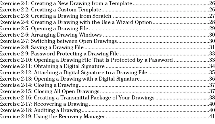
Exercise 2-1: Creating a New Drawing from a Template ...26Exercise 2-2: Creating a Custom Template...26
Exercise 2-3: Creating a Drawing from Scratch ...27
Exercise 2-4: Creating a Drawing with the Use a Wizard Option...28
Exercise 2-5: Opening a Drawing File...29
Exercise 2-6: Arranging Drawing Windows ...30
Exercise 2-7: Switching between Open Drawings...30
Exercise 2-8: Saving a Drawing File ...31
Exercise 2-9: Password-Protecting a Drawing File ...33
Exercise 2-10: Opening a Drawing File That Is Protected by a Password ...33
Exercise 2-11: Obtaining a Digital Signature ...34
Exercise 2-12: Attaching a Digital Signature to a Drawing File ...35
Exercise 2-13: Opening a Drawing with a Digital Signature...36
Exercise 2-14: Closing a Drawing...37
Exercise 2-15: Closing All Open Drawings...37
Exercise 2-16: Creating a Transmittal Package of Your Drawings ...38
Exercise 2-17: Recovering a Drawing ...40
Exercise 2-18: Auditing a Drawing...40
Exercise 2-19: Using the Recovery Manager ...41
Chapter 3: Customizing Your Work Environment
Exercise 3-1: Changing the Display of Interface Elements ...46Exercise 3-2: Enabling Hardware Acceleration and Adjusting Adaptive Degradation ....48
Exercise 3-3: Creating a User Profile ...51
Exercise 3-4: Setting a User Profile Current and Making Changes ...52
Exercise 3-5: Exporting and Importing a User Profile...52
• Exercise 3-6: Creating a New Workspace and Setting a Workspace Current ...54
• Exercise 3-7: Organizing Your Workspaces ...55
• Exercise 3-8: Creating a Custom Command ...57
• Exercise 3-9: Creating a Custom Toolbar ...57
Chapter 4: Transitioning from 2D to 3D
Exercise 4-1: Creating a Wireframe Model Using Coordinate Entry...65• Exercise 4-2: Using Object Snaps in 3D Space ...66
• Exercise 4-3: Using Object Snap Tracking ...68
Exercise 4-4: Changing the Current Elevation of a Drawing ...70
Exercise 4-5: Customizing the Display of the UCS Icon ...74
• Exercise 4-6: Changing the UCS and Creating a Named UCS ...75
• Exercise 4-7: Using Dynamic UCS ...77
Chapter 5: Viewing a 3D Model
Exercise 5-1: Using Orthogonal and Isometric Preset Viewpoints...81Exercise 5-2: Changing the Viewpoint with the Viewport Presets Dialog Box ...82
Exercise 5-3: Defining a Viewpoint with the Tripod and Compass ...83
Exercise 5-4: Navigating a 3D Model Using the Basics ...84
• Exercise 5-5: Orbiting around a Model ...86
Exercise 5-6: Changing the Current Projection...88
• Exercise 5-7: Looking Around a Model ...90
• Exercise 5-8: Creating a Named View...93
• Exercise 5-9: Modifying a Named View ...93
Exercise 5-10: Setting a Named View Current ...94
• Exercise 5-11: Creating a Camera ...95
• Exercise 5-12: Modifying a Camera ...96
Exercise 5-13: Assigning a Background with a Solid Color to a Camera ...97
• Exercise 5-14: Assigning a Background with an Image to a Camera ...98
Exercise 5-15: Applying a Visual Style to the Current Viewport...100
• Exercise 5-16: Creating a Custom Visual Style ...101
Exercise 5-17: Adding a Visual Style to a Tool Palette ...101
Exercise 5-18: Changing the Display Quality of Curved 3D Solids ...104
Chapter 6: Taking the Plunge into 3D
Exercise 6-1: Adjusting the Grid and Snap ...110Exercise 6-2: Adjusting the Limits of a Drawing ...110
Exercise 6-3: Creating New Layers for Modeling ...112
Exercise 6-4: Creating a Wireframe Model Using 3D Polylines and Lines ...114
• Exercise 6-5: Creating and Modifying a Helix...116
Exercise 6-6: Giving 2D Objects Thickness ...117
• Exercise 6-7: Extruding 2D Objects ...119
• Exercise 6-8: Creating a Region...120
• Exercise 6-9: Modifying Regions ...121
Exercise 6-10: Collecting Information About a Region ...123
• Exercise 6-11: Moving an Object in 3D...124
• Exercise 6-12: Rotating an Object in 3D...126
• Exercise 6-13: Aligning Objects in 3D with the 3DALIGN Command...127
Exercise 6-14: Aligning Objects in 3D with the ALIGN command...128
Exercise 6-15: Mirroring an Object in 3D...128
Exercise 6-16: Creating a 3D Rectangular Array ...129
Exercise 6-17: Creating a 3D Polar Array...130
Chapter 7: Additional Exercises: Making the Transition
Exercise 7-1: Navigating an Assembly of Parts...133• Exercise 7-2: Creating a Named View with a Gradient Background ...134
• Exercise 7-3: Starting with a 2D Drawing and Ending with a 3D Part ...135
• Exercise 7-4: Bringing the New Part and Assembly Together...136
• Exercise 7-5: Aligning the Part ...137
Chapter 8: Modeling with Solids
Exercise 8-1: Creating a 3D Solid Box ...143Exercise 8-2: Creating a 3D Solid Wedge...145
Exercise 8-3: Creating a 3D Solid Pyramid ...146
Exercise 8-4: Creating a 3D Polysolid...147
Exercise 8-5: Creating a 3D Solid Sphere ...149
xv
Table of Exercises
Exercise 8-6: Creating a 3D Solid Cylinder ...150
Exercise 8-7: Creating a 3D Solid Cone ...151
Exercise 8-8: Creating a 3D Solid Torus ...152
Exercise 8-9: Adding 3D Solids Together...154
Exercise 8-10: Subtracting a 3D Solid from Another 3D Solid...154
Exercise 8-11: Creating a New 3D Solid through the Intersection of Two 3D Solids...155
• Exercise 8-12: Creating a New 3D Solid Based on the Interference of Two 3D Solids....156
• Exercise 8-13: Revolving a Closed 2D Object to Create a 3D Solid...158
• Exercise 8-14: Sweeping a Closed 2D Object to Create a 3D Solid ...159
• Exercise 8-15: Lofting Closed 2D Objects to Create a 3D Solid...160
Chapter 9: Modifying and Analyzing Solids
Exercise 9-1: Modifying 3D Solids Using the Properties Palette...165• Exercise 9-2: Modifying 3D Solids with Grips ...166
• Exercise 9-3: Selecting Subobjects on a 3D Solid ...168
• Exercise 9-4: Stepping Back in Time to Modify a 3D Solid ...171
• Exercise 9-5: Adding Fillets and Chamfers ...172
Exercise 9-6: Creating a Slice of Model ...174
Exercise 9-7: Deleting a Chamfer ...176
Exercise 9-8: Tapering a Face...177
• Exercise 9-9: Shelling Out a 3D Solid...178
Exercise 9-10: Imprinting a 2D Object onto a 3D Solid ...179
• Exercise 9-11: Modifying a 3D Solid with PRESSPULL...180
Chapter 10: Creating Section and Auxiliary Views from Models
• Exercise 10-1: Creating a Section Plane and Using Live Sectioning ...189• Exercise 10-2: Creating a 2D Section View...189
• Exercise 10-3: Creating Ortho, Auxiliary, and Section Views of a 3D Model — Part 1 ...191
• Exercise 10-4: Creating Ortho, Auxiliary, and Section Views of a 3D Model — Part 2 ...193
• Exercise 10-5: Flattening a 3D Solid...195
Chapter 11: Additional Exercises: Modeling with Solids
Exercise 11-1: Creating 3D Primitives of the Solid Kind ...198• Exercise 11-2: Sweeping a 2D Profile to Create a Complex 3D Solid ...199
Exercise 11-3: Subtracting from a 3D Solid ...202
• Exercise 11-4: Adding Fillets to a 3D Solid ...203
Chapter 12: Modeling with Surfaces
• Exercise 12-1: Creating a 3D Face ...211Exercise 12-2: Creating a 3D Planar Mesh ...212
Exercise 12-3: Creating a 3D Mesh Box or Wedge ...213
Exercise 12-4: Creating a 3D Mesh Pyramid...215
Exercise 12-5: Creating a 3D Mesh Sphere ...217
Exercise 12-6: Creating a 3D Mesh Dome ...217
• Exercise 12-7: Creating a 3D Mesh Cone...219
Exercise 12-8: Creating a 3D Mesh Torus ...220
Exercise 12-9: Creating a Planar Surface ...221
Chapter 13: Complex Surface Modeling
• Exercise 13-1: Capping a 3D Mesh with an Open Top Using a Free-Form Polygon Mesh ...224Exercise 13-2: Creating a 3D Mesh from a Polyface Mesh ...225
• Exercise 13-3: Revolving a Closed 2D Object to Create a 3D Mesh...227
Exercise 13-4: Creating a Tabulated 3D Mesh ...229
• Exercise 13-5: Creating a Ruled 3D Mesh ...230
Exercise 13-6: Creating a 3D Mesh Based on Four Adjoining Edges ...231
Chapter 14: Modifying Surfaces
• Exercise 14-1: Hiding Edges of 3D Faces ...237Exercise 14-2: Modifying a Polygon Mesh ...240
• Exercise 14-3: Modifying a Surface Object ...242
Chapter 15: Additional Exercises: Modeling with Surfaces
• Exercise 15-1: Creating the Outer Housing for a Bearing Using 3D Meshes ...246Exercise 15-2: Smoothing the 3D Mesh for the Outer Housing of the Bearing ...247
Exercise 15-3: Adding Sphere Primitives to the Bearing ...247
Exercise 15-4: Finishing the Holes in the Gear Using Revolved Surfaces...249
• Exercise 15-5: Creating a Hub for the Gear Using a Lofted Surface ...250
• Exercise 15-6: Completing the Center of the Gear Using an Extruded Surface ...251
Chapter 16: Lighting
• Exercise 16-1: Creating User-Defined Lights ...263• Exercise 16-2: Modifying User-Defined Lights...268
• Exercise 16-3: Adjusting Global Lighting ...270
Exercise 16-4: Using the Render Exposure Dialog Box ...270
Chapter 17: Materials
• Exercise 17-1: Creating Materials ...279• Exercise 17-2: Attaching Materials to 3D Objects ...283
Exercise 17-3: Controlling the Direction of a Material ...285
Chapter 18: Rendering and Animating
• Exercise 18-1: Creating a Rendering and Saving It to an Image File...290Exercise 18-2: Creating and Using a Render Preset ...291
Exercise 18-3: Adding Depth Cueing to a Rendering...293
• Exercise 18-4: Following the Path to Create an Animation ...297
Chapter 19: Additional Exercises: Visualizing the Design
• Exercise 19-1: Adding User-Defined Lights...300• Exercise 19-2: Creating Rubber Compound and Chrome Materials...301
• Exercise 19-3: Attaching Materials ...302
• Exercise 19-4: Adding Depth to the Model and Creating a Presentation-Quality Rendering ...303
Exercise 19-5: Creating an Animation ...304
Chapter 20: Plotting to a Hardcopy or an Electronic File
• Exercise 20-1: Creating a Raster Image Plotter and Plotting to an Image File ...308Exercise 20-2: Creating a New Layout by Using the Layout Wizard...310
Exercise 20-3: Creating a Single Viewport and Modifying Its Properties ...313
• Exercise 20-4: Plotting a Drawing to a Raster Image File...315
Exercise 20-5: Creating a Web Page of Your Designs with Publish to Web ...318
Chapter 21: Importing and Exporting 3D Models
• Exercise 21-1: Creating a 3D DWF File...326• Exercise 21-2: Embedding a 3D DWF File into PowerPoint ...327
Introduction
A
utoCAD is different from many other applications that you might already know and use everyday, and that’s primarily due to how it has evolved over the past two decades. The CAD industry is always striving for change in an attempt to improve the processes that are used to create drawings. (CAD stands for Computer-Aided Draftingor Computer-Aided Design, depending on whom you ask.) One of the latest trends that has started to take off and redefine the industry in recent years is 3D modeling.Although AutoCAD is primarily thought of as a CAD application used for 2D designs, it has a powerful 3D modeling engine that allows you to create 3D models of buildings or small parts used in a machine. 3D modeling in AutoCAD was introduced over a decade ago with AutoCAD R13 (and even before that as an add-on called Autodesk Modeling Extension for AutoCAD R12), but creating 3D models was very time consuming. In recent releases of AutoCAD, the 3D model-ing features have been completely overhauled to allow conceptual designmodel-ing in AutoCAD and to create high-quality presentation renderings with less effort.
AutoCAD 2008 not only gives you the 2D drafting tools that you’ve come to use everyday, but it also provides a robust set of tools for 3D modeling and visualizing the 3D models you can create. This workbook helps you get up to speed fast with the 3D modeling features of AutoCAD, allowing you to be more productive in a shorter period of time than if you tried to go it alone.
About This Book
AutoCAD 2008 3D Modeling Workbook For Dummiesgives you an understanding of all the fea-tures that you need to know in order to work efficiently with 3D models in AutoCAD. This book is different from other For Dummiesbooks you might have read; it provides the infor-mation that you need to know in order to work in 3D and gives you opportunities to try out what you discover throughout the book.
The book is organized to allow you to work with procedural- and workflow-based exercises. The procedural-based exercises allow you to try out the concepts covered in the book, whereas the workflow-driven exercises give you an idea of how the concepts in the book are applied when working on a 3D model.
Conventions Used in This Book
When you need to type text at the command line, in a dynamic input tooltip, in a text box, or any other place, the text appears in bold typeface (for example, “Enter perspectiveat the command line”). Examples of AutoCAD prompts appear in a special typeface.
Foolish Assumptions
You should know how to use the Windows operating system and understand the basics of navigating folders and starting applications. To take advantage of everything that is in this book and the features that AutoCAD offers, you need at least a dial-up Internet connection (preferably a high-speed cable or DSL connection). As long as you have AutoCAD installed on the computer in front of you and a connection to the Internet, you’re ready to get started.
This book also assumes that you understand how to work with the 2D drafting features of AutoCAD. If you need to brush up on your 2D skills, pick up AutoCAD & AutoCAD LT All-in-One Desk Reference For Dummies.
How This Book Is Organized
The following sections describe the different parts that this book is organized into.
Part I: Introducing AutoCAD
Part I covers working with the user interface elements in AutoCAD and some of the basic file management concepts that you should be familiar with before creating and modify-ing 3D models. Chapter 1 focuses on the different user interface elements that AutoCAD offers for changing settings and accessing commands related to 3D modeling along with getting help when you might need it. Chapter 2 covers some basics of working with drawing files, and Chapter 3 covers customizing the AutoCAD user interface to make sure you have access to the commands that you want to use when you need them.
Part II: Going from 2D to 3D
Part II helps you transition your skills working on 2D drawings in AutoCAD to their 3D equivalent. Chapter 4 provides an overview of the different types of 3D models that you can create with AutoCAD and how to specify 3D coordinate values. Chapter 5 explains how to navigate around a 3D model as well as customizing how a 3D model is displayed in the current view so you can better see how it looks. Chapter 6 takes a look at the different drafting aids that you can use when modeling in AutoCAD, and it covers some of the basic 3D objects that you can create. You also find out how to use the general 3D modifying commands that you can use with 3D objects. Chapter 7 gives you an opportunity to apply some of the topics covered in the other chapters from this part in a workflow-driven approach to modeling in AutoCAD.
Part III: 3D Modeling — Solid Modeling
the other chapters in this part in a workflow-driven approach to working with solid models in AutoCAD.
Part IV: 3D Modeling — Surfaces
Part IV focuses on modeling with 3D faces, meshes, and surface objects to create 3D surface models. Chapter 12 covers how to create 3D faces, planar meshes, mesh primitives, and planar surface objects. Chapter 13 focuses on the creation of complex meshes and surface objects using operations like revolving, lofting, and sweeping. Chapter 14 explains how you can modify 3D faces, meshes, and surface objects after you create them. Chapter 15 offers additional exercises that cover many of the topics from the other chapters in this part in a workflow-driven approach to working with surface models in AutoCAD.
Part V: Visualizing the Design
Part V takes you through the process of adding lighting and materials to a 3D model before creating a photorealistic rendering. Chapter 16 covers creating various types of lights in your models to show contrasts on surfaces with illuminated and shaded areas. Chapter 17 focuses on creating and applying materials to 3D objects to give them realistic colors and textures that represent how the objects in the model might look after they’re manufactured and assembled. Chapter 18 introduces you to creating a rendering from your 3D model after you add lights and materials to it. You also find out about some of the advanced rendering features in Chapter 18 along with using the animation features that come with AutoCAD. Chapter 19 contains additional exercises that reinforce the topics covered in the other chapters from this part.
Part VI: Model Interchange
Part VI explains many of the different ways that you can share designs with others. Chapter 20 focuses on creating layouts with floating viewports to create plotted views of your 3D models and to configure a plotter to output raster image files. Chapter 21 introduces you to the different file formats that you can exchange your 3D models in for both CAD and non-CAD users.
Part VII: The Part of Tens
Part VII provides additional information that extend your experience with AutoCAD and 3D modeling beyond this book. Chapter 22 provides an overview of the new enhancements in AutoCAD 2008 that are related to both 2D drafting and 3D modeling. Chapter 23 is packed full of links to AutoCAD Web sites that cover 2D drafting and 3D modeling, along with links to industry-related Web sites where you can find informa-tion about software add-ons to AutoCAD that can be used for analyzing 3D models or sites with 3D models that you can use in your own models.
Appendixes
Appendix A provides a listing of some of the commonly used terms that are introduced in this book, and it helps you to speak the 3D modeling lingo like a seasoned veteran. Appendix B provides you with information about the files and videos that are on the DVD that comes with this book.
3
The DVD-ROM
The DVD-ROM that accompanies this workbook plays an intricate part in the workbook experience. All the files for completing the exercises are contained on the DVD-ROM along with the videos of select exercises that help explain the steps of an exercise if you get stuck.
Icons Used in This Book
This book uses the following icons to denote paragraphs that are of special interest:
This icon indicates a question-and-answer pairing that helps tie the concepts covered under a topic with how you might use the concepts in the software.
This icon indicates information that can help you complete a task faster or help you not fall too far from the path of success.
This icon indicates a video is available for an exercise. If you need some help completing an exercise, you can watch the video to see how the exercise is completed step by step.
This icon gives you a dash of extra information if you haven’t had enough caffeine yet for the day. AutoCAD is a complex program, and it takes time to put all the puzzle pieces together, so use these friendly reminders to stay on the right track.
This icon helps you avoid potential pitfalls in AutoCAD that can get you into trouble. Failure to adhere to the message may result in an undesired side effect to your 3D model or additional work that could have been avoided.
Where to Go from Here
This book is organized to allow you the freedom of moving from part to part or chap-ter to chapchap-ter in any order that you want. However, each of the chapchap-ters build on con-cepts that are covered in previous chapters of the book; so if you’re relatively new to 3D in AutoCAD, I recommended that you start at the front of the book and work your way towards the back. If you’re experienced with AutoCAD, you might want to skim through the first three chapters of the book and then dive into Chapter 4.
This book was written with the assumption that you already know how to use the 2D drafting features of AutoCAD. Although I do cover many topics that cross over between 2D and 3D, I primarily focus on using features for 3D modeling. If you want to brush up on the latest 2D drafting features in AutoCAD or some of the drawing precision tools that AutoCAD offers, I suggest getting AutoCAD & AutoCAD LT All-in-One Desk Reference For Dummies.
Part I
Chapter 1
AutoCAD and the User Interface
In This Chapter
䊳Launching AutoCAD and using command line switches
䊳Looking at the user interface of AutoCAD
䊳Using commands and providing input
䊳Getting help from AutoCAD
B
eing proficient with AutoCAD and its user interface can help make drafting tasks easier based on how familiar you are with all the tools that are just a click away. The exercises in this chapter give you an understanding of how to use the various interface elements that AutoCAD has to offer to make sure you have the tools available when you need them.The exercises in this chapter use the AutoCAD Classic workspace. To set the AutoCAD Classic workspace current, choose Tools➪Workspaces➪AutoCAD Classic. For more information on using and creating workspaces, see Chapter 3.
Launching AutoCAD
AutoCAD is one of the most popular computer-aided drafting applications on the market today. You can use it to design plans for residential homes and complex drawings such as paper-converting machines and circuit boards. To become efficient with AutoCAD, you should get to know as many methods of launching the program as possible.
1.
How can you start AutoCAD? A. From the Start menuB. From a shortcut on the desktop, taskbar, or Quick Launch toolbar
C. Insert the product CD/DVD into the CD/DVD-ROM
D. By opening a drawing file
Exercise 1-1: Launching AutoCAD
In this exercise, you add a shortcut to the desktop, the Start menu, and the Quick Launch toolbar.
⻬Add a shortcut for AutoCAD to the Start menu.Right-click the AutoCAD short-cut on the desktop and choose Pin to Start Menu.
⻬Add a shortcut for AutoCAD to the Quick Launch toolbar.Drag and drop the AutoCAD shortcut from the desktop into place on the Quick Launch toolbar. If the Quick Launch toolbar isn’t visible on the taskbar, right-click the taskbar and choose Toolbars➪Quick Launch.
AutoCAD allows you to use what are called command line switches.Command line switches automate some of the tasks that are normally performed each time you start AutoCAD. Removing manual steps from the start-up process ensures that the drawings you create are more consistent with each; then you can worry more about the models that you need to create than all the intricate setup processes. You use them in con-junction with desktop shortcuts that define the default template, workspace, and user profile that are set up when AutoCAD first starts.
Command Line Description Switch
/p Allows you to specify which user profile to use when AutoCAD
starts. For information on user profiles, see Chapter 3.
/t Allows you to specify which drawing template to use for the
default drawing that is created when AutoCAD launches. For more information on drafting templates and creating a new drawing, see Chapter 2.
/w Allows you to specify which workspace to use when AutoCAD
starts. For information on user workspaces, see Chapter 3.
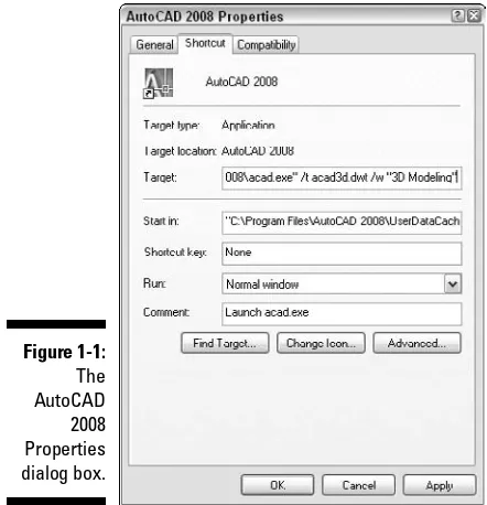
You can use more than one command line switch at a time with a shortcut; you just need to use them correctly. Figure 1-1 shows an example of using the /tand /w com-mand line switches.
Exercise 1-2: Customizing a Desktop Shortcut with Command Line Switches
In this exercise, you customize a desktop shortcut (see Exercise 1-1) to specify a tem-plate for the default drawing and which workspace should be set current when AutoCAD is first launched.
1.
Access the Properties dialog box for your AutoCAD shortcut.2.
In the Properties dialog box, click the Shortcut tab.3.
On the Shortcut tab, position the cursor at the end of the path to the acad.exe file in the Target text box and click.4.
Press the spacebar once to add a space after the executable file’s path. Then enter this text:/t acad3d.dwt /w “3D Modeling”
The /tcommand line switch uses the drawing template acad3d.dwtthat ships with AutoCAD to create the default drawing, and the /wcommand line switch sets the 3D modeling workspace current. After you add the text in the Target text box, the text looks like the following:
“C:\Program Files\AutoCAD 2008\acad.exe” /t acad3d.dwt /w “3D Modeling”
5.
Click the General tab and change the name of the shortcut in the Name text box near the top to My AutoCAD.6.
Click OK to save the changes.7.
Double-click the shortcut to test the changes made.AutoCAD launches with the default drawing based on the acad3d.dwtfile and the 3D Modeling workspace is set current.
If the name of the drawing template, profile, or workspace contains a space, you must wrap the name with double quotation marks in order for AutoCAD to interpret the command line switches properly.
For additional information on other command line switches that are available for use with an AutoCAD shortcut, see the Customize Startup topic in the AutoCAD Online Help system.
Navigating the User Interface
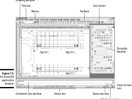
The AutoCAD user interface — or UIas it’s often referred to — can be very overwhelm-ing, but it doesn’t have to be. All you need is some understanding of how things are laid out and what the various UI elements are. AutoCAD, like other Windows-based applications, has pull-down menus, toolbars, a document area, and a status bar area, but AutoCAD also has some unique user interface elements that aren’t found in a lot of other applications. Some of the unique interface elements are a Command Line window, dynamic input tooltips, and dockable windows. Figure 1-2 shows many of the different user interface elements that are found in AutoCAD.
9
Chapter 1: AutoCAD and the User Interface
Drawing window
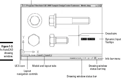
The drawing window(see Figure 1-3) is the main area in the middle of AutoCAD where you add and modify objects in the designs that you create. When you create a new drawing or open an existing drawing, a drawing window appears. Each open drawing has its own drawing window. Along the bottom of each drawing window, you find these items:
⻬A series of tabssimilar to those found in a spreadsheet program; these tabs repre-sent where you create your model (Model tab) and the layouts used for plotting different views of your model.
You can turn off the Model tab and layout tabs if you don’t want them displayed. In their place are two buttons that allow you to switch to a different layout tab.
⻬To the left of the tabs are navigation controlsthat allow you to scroll to the first, last, next, or previous layout tab if all the tabs can’t be displayed along the bottom of the drawing window at a time.
⻬The drawing status bar along the bottom displays settings specific to the drawing, such as the current annotation scale. If you disable the drawing status bar, the options are displayed in the status bar area of the application window instead.
Menus
Command Line window Drawing window
Toolbars
Title bar Info Center
Status bar Status bar tray
Status bar menu
Clean Screen icon Dockable window
Exercise 1-3: Navigating the Drawing Window
Practice using some of the user interface elements of the drawing window.
1.
Create a new drawing based on the ANSI A (portrait) -Color Dependent Plot Styles.dwttemplate that comes with AutoCAD.In AutoCAD, choose File➪New. In the Select Template dialog box, select the ANSI A (portrait) -Color Dependent Plot Styles.dwttemplate file and click Open. The drawing templates that come with AutoCAD are located in the Templates folder at C:\Documents and Settings\user name\Local Settings\Application Data\Autodesk\AutoCAD 2008\R17.1\enu; substitute user namewith your Windows login name.
Turn to Chapter 2 to find out how to create a new drawing.
2.
Click the Model tab and layout tabs to view the contents of each one.3.
Right-click one of the tabs and choose Hide Layout and Model Tabs to toggle the display for the layout tabs.To display the tabs again, right-click the Model or Layout button in the status bar area and choose Display Layout and Model Tabs.
4.
View the contents of each of the layouts by clicking the Model and Layout but-tons in the application window’s status bar; they’re displayed to the right of the button labeled LWT (as shown in Figure 1-4).5.
Click the Status Bar Menu button to the left of the Clean Screen icon on the appli-cation status bar (refer to Figure 1-2). Choose Drawing Status Bar. Make sure that a check mark is next to Drawing Status Bar.Some of the icons in the status bar tray move to the bottom of the drawing window along with the controls for annotation scale.
Drawing window title bar
UCS icon Layout navigation controls
Model and layout tabs
Drawing window status bar
Drawing window status bar tray
Info bar menu
Dynamic Input Tooltips
Crosshairs
Figure 1-3: An AutoCAD drawing window.
11
6.
Turn off the Drawing Status Bar setting.Click the button to the right of the Layout button named Additional Layouts to display a list of all the layouts in the drawing.
Press Ctrl+Page Up to navigate to the previous layout or Ctrl+Page Down to navi-gate to the next layout in the drawing.
Command Line window
The Command Line window by default is displayed between the drawing window and the status bar area. If you don’t like its position, you can dock it above or along the left or right side of the drawing window. The Command Line window plays a key role in inputting commands, options, and values to create and modify objects; it also displays command prompts and messages to let you know what AutoCAD is waiting for.
If you want to gain additional room in the AutoCAD application window, you can close the Command Line window. Press Ctrl+9 to toggle the display of the Command Line window on and off. When the Command Line window is hidden, command prompts and options are displayed in dynamic tooltips. Press F12 to toggle the display of dynamic tooltips. For more information on dynamic input, see the “Dynamic input” section later in this chapter.
Text window
The Text window displays a running history of the commands and options that you previously entered in the Command Line window or at the dynamic input tooltip. You won’t need the Text window very often, but if you need to see what you did a few com-mands ago, press F2 to bring up the Text window.
Status bar
The status bar allows you to quickly access drafting settings and other settings that are used for some of the features. Most of the settings on the status bar allow you to toggle drafting settings on or off without opening a dialog box or remembering a shortcut key combination. Also, you can right-click most buttons to access options that allow you to change the behavior of the drafting settings.
Layout tab (most recent layout)
Model tab Additional layouts Figure 1-4:
Table 1-1 lists the different buttons on the status bar.
Table 1-1
Status Bar Buttons
Button Name Description
Coordinates Toggles among absolute, relative, and polar coordinate display settings
Snap Mode Toggles grid or PolarSnap on and off
Grid Display Toggles the display of the grid on and off
Ortho Mode Toggles ortho mode on and off
Polar Tracking Toggles polar tracking on and off
Object Snap Toggles running object snaps on and off
Object Snap Tracking Toggles object snap tracking on and off
Dynamic UCS Toggles dynamic UCS on and off
Dynamic Input Toggles dynamic input on and off
Show/Hide Lineweight Toggles the display of lineweights on and off
Model/Paper Space Toggles between model and paper space
Model/Layout and Toggles between model and paper space, Additional Layouts and switch paper space layouts
Minimize/Maximize and Toggles between maximized and minimized Viewport Navigation viewport states, and allows you to switch
among different viewports
Status Bar Tray Displays the current notification icons for the features that are in use in the current session and drawing
Exercise 1-4: Using the Status Bar
In this exercise, you create a new drawing and use some of the drafting settings that are available on the status bar.
1.
Choose File➪New.2.
In the Select Template dialog box, double-click the acad.dwtdrawing template file.13
3.
Choose Draw➪Line, or type lineat the command prompt and press Enter.4.
Pick a point in the drawing window to start drawing a line.5.
On the status bar, click DYN until the button appears popped out. When a button is popped out, the drafting setting is turned off, and in this case you toggled Dynamic Input off.Move the crosshairs in the drawing window; no dynamic input tooltips are dis-played trailing the crosshairs. The dynamic input tooltip is an extension of the Command Line window that displays the current command prompt and input boxes that allow you to specify coordinate values, distances, or angles among other values for the current command. For more information on dynamic input, see the “Dynamic input” section later in this chapter.
6.
Turn on Dynamic Input.Move the crosshairs in the drawing window; the dynamic input tooltips display trailing the crosshairs. With the LINE command active yet, you should see the command prompt Specify next pointand a down arrow that allows you to access the available command options. After the command prompt, you see two input boxes that allow you to specify the X- and Y-coordinate values for the end point for the line.
7.
Turn on ortho mode.Move the crosshairs in the drawing window; you can draw a straight line only in 90-degree increments starting with 0 because ortho mode constrains the coordi-nate value horizontal or vertical from the previous point specified.
8.
Turn off ortho mode.You can now create a line at any angle that you want to.
9.
Press Esc to exit the LINE command.Exercise 1-5: Controlling the Display of Controls on the Status Bar
For this exercise, open a drawing (a new one or one from a previous exercise). Practice controlling the display of controls on the status bar.
1.
On the right side of the status bar area, click the Status Bar Menu button (located to the left of the Clean Screen icon).2.
Select the controls that you want to display or hide on the status bar.The items selected are displayed, and the ones that aren’t selected are currently hidden. It’s a good idea to display only the controls that you frequently use.
Status bar tray
Table 1-2 lists the different tray icons that are available in AutoCAD.
Table 1-2
Status Bar Icons
Button Name Description
Toolbar/Window Lock Controls whether toolbars and dockable windows (palettes) can be moved. Locking/unlocking can affect all toolbars or dockable windows. You can specify which are floating or docked.
CAD Standards Identifies that a drawing has CAD Standards associ-Notification ated with it. Access the tools related to CAD
stan-dards and receive notifications when the drawing contains standards violations.
External Reference Identifies that External Reference drawings are Notification attached. Receive notifications when the files have
been updated and need to be reloaded.
Plot Notification Accesses information about recently plotted draw-ing files.
Attribute Extraction Identifies that a table object in the drawing is linked Notification to the attributes of blocks in the drawing and receive
notifications when the table object becomes out of date.
Trusted Autodesk Indicates whether the drawing was created with an DWG application developed by Autodesk or using RealDWG.
Clean Screen Toggles the state of Clean Screen.
Data Link Indicates if data in a table is linked to an external data source.
Vault Indicates whether you are currently logged into Autodesk Vault. The icon is available only when Autodesk Vault is installed on your computer.
Exercise 1-6: Controlling the Display of Icons and Notification Balloons
For this exercise, open a drawing (a new one or one open from a previous exercise). Practice changing the global settings for the status bar tray and notification balloons.
1.
On the right side of the status bar, click the Status Bar Menu button (located to the left of the Clean Screen icon).2.
Choose Tray Settings.3.
In the Tray Settings dialog box, click Display Icons from Services so it’s deselected.4.
Click OK.The status bar tray is now hidden, with the exception of the Status Bar Menu and Clean Screen buttons.
15
5.
Open the Tray Settings dialog box, re-enable Display Icons from Services, and select Display Time and 5 seconds from the drop-down list.The notification balloons now close automatically after 5 seconds.
6.
Click OK.Toolbars
Toolbars are some of the most commonly used user interface elements in a Windows-based application. Toolbars allow you to quickly access commands from an organized grouping of tools instead of using pull-down menus. A toolbar contains buttons that you click to activate a command, and it has controls that allow you to select an option from a drop-down list or enter text into a text box.
Some toolbars contain flyouts,which have multiple tools on them that perform similar tasks. A flyout on a toolbar is indicated by a button displaying a black arrow in the lower-right corner of the button’s image.
Figure 1-5 shows the main parts of a toolbar.
You can dock toolbars along the edge of the application window, or you can have them floating. The state that the toolbar is in doesn’t affect how the buttons and controls work, but if a toolbar that contains a drop-down list is docked on the left or right side of the application window, the control isn’t displayed. When a toolbar is docked, the gripper bar is displayed at the top or left side of the toolbar based on how it’s docked; if the toolbar is floating, a title bar appears at the top with the name of the toolbar.
Most people prefer toolbars to pull-down menus because they offer quick access to commonly used commands, and toolbar icons make the commands easy to recognize. AutoCAD comes with 37 toolbars, but you can create your own custom commands and toolbars to access the commands that you use on a regular basis with ease. For more information on creating your own custom commands and toolbars, see Chapter 3.
Exercise 1-7: Displaying, Hiding, and Repositioning a Toolbar
For this exercise, open a drawing (a new one or one from a previous exercise). Practice displaying, hiding, and repositioning a toolbar.
1.
Right-click any displayed toolbar and choose 3D Navigation from the shortcut menu to display the 3D Navigation toolbar.Toolbars that are currently displayed have a check mark next to them on the shortcut menu, and the ones that are hidden don’t.
2.
If the 3D Navigation toolbar is currently docked, click the gripper bar and drag the toolbar over the drawing window.You can lock the position of toolbars and dockable windows by clicking the Toolbars/Window Lock icon in the status bar tray.
3.
Click the title bar of the 3D Navigation toolbar and drag the toolbar along the left side of the application window of AutoCAD. Release the mouse button to dock the toolbar.When the toolbar gets close enough to be docked, the drag preview of the tool-bar switches from a horizontal to a vertical orientation.
Hold down Ctrl when dragging a toolbar or dockable window to keep it from docking along the edge of the application window.
4.
Close the toolbar.Menus
Menus — or pull-down menus — are located on the menu bar and allow you to access more commands than any other user interface in AutoCAD (other than the command prompt). You can find most of the commands that you need when working on a draw-ing on one of the 12 menus in AutoCAD. The menus in AutoCAD contain commands that have been organized into related groups; for instance, commands that create objects are on the Draw menu, and ones used for dimensioning are on the Dimension menu. The main menus that are available in AutoCAD are located along the top of the application window. When clicked, they appear to drop down from the main menu’s name.
AutoCAD also offers context-sensitive menus that are available when you right-click the drawing window. Context-sensitive menus offer different options based on whether a command is active or even whether any objects are selected in the drawing before you right-click. Both the main and shortcut menus use submenus to organize options that are similar. Submenus are indicated by a small black arrow that points to the right.
Menu items use special indicators that let you know what happens when you click or access the item without using the menu in the future:
⻬A series of 3 periods (. . .):A dialog box displays when you choose the menu item.
⻬Shortcut key combination:The keyboard command is displayed to the right of the menu item’s caption. For example, Ctrl+N is displayed next to the New menu item. You can press Ctrl+N to start the NEW command.
If you hold down Shift before right-clicking, you can access the Object Snap Cursor menu, which allows you to select an object snap override.
Dockable windows
Dockable windows — or palettes — are one of the newest user interfaces in AutoCAD. They allow you to access settings and options without the need of closing them when you’re done. AutoCAD offers a number of dockable windows that allow you to modify the properties of an object; calculate distances; convert values to different units of measurement; access reusable objects (blocks, materials, and visual styles) when creat-ing or modifycreat-ing a drawcreat-ing; or work with sheet sets. AutoCAD comes with 14 dockable windows, and you can launch most of them by choosing Tools➪Palettes.
17
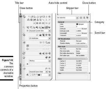
You can dock, as the name implies, dockable windows or have them float like a toolbar. However, when docked or floating, a dockable window can still take up a moderate amount of space in AutoCAD, which can reduce the available space you have for the drawing window. That’s why you can auto-hide dockable windows. The Auto-hide set-ting collapses the dockable window when the cursor isn’t over it, which helps to reduce it to the same size as a docked toolbar. Figure 1-6 shows the common controls that all dockable windows have in common. Manipulating the position and display of a dock-able window is similar to manipulating a toolbar.
Exercise 1-8: Manipulating the Display of a Dockable Window
For this exercise, open a drawing (a new one or one from a previous exercise). Practice displaying, auto-hiding, and repositioning a dockable window.
1.
Choose Tools➪Palettes➪Properties.2.
If the Properties window is currently docked, click the gripper bar and drag it over the drawing window.3.
Click the Auto-hide control on the title bar.The dockable window collapses, and only the title bar is displayed. Moving the crosshairs/cursor over the title bar causes it to expand.
4.
Click the title bar and drag the palette to the right of the drawing window. Release the mouse button when the preview of the palette changes to dock the palette.Hold down Ctrl when dragging a toolbar or palette to keep it from docking along the edge of the application window.
Close button
Auto-hide control
Title bar Auto-hide control
Gripper bar
Close button
Category Scroll bar
Properties button
5.
Click the Auto-hide control (which looks like the Minimize icon) to the left of the gripper bar.The dockable window collapses, and only the title bar is displayed. Moving the crosshairs/cursor over the title bar causes it to expand.
6.
Close the dockable window.Click the X button on the dockable window or choose Tools➪Palettes➪
Properties.
Giving AutoCAD Directions
As you might have noticed by all the different user interfaces that AutoCAD offers, you can start commands and input options in a number of ways. You can use commands to start a specific task that displays prompts or a dialog box for input.
The easiest way to start a command is to type it in the Command Line window. After you start a command, you do one of the following:
⻬Provide input if a prompt is displayed in the Command Line window or at a dynamic input tooltip.
⻬Provide input in the controls of a dialog box that is displayed.
⻬Nothing; the command simply ends because no input is required.
19
Chapter 1: AutoCAD and the User Interface
3.
Besides typing the command at the command prompt, how else can you start a command? A. Choose a menu item from a pull-down menu or shortcut menu.B. Use the Command Prompt window in Windows.
C. Use a toolbar or the dashboard.
It’s all in the name
Not all commands in AutoCAD are created equally: You can use some commands when other commands are in use, whereas you can use certain commands only when no other command is active. When you’re using a command that creates or modifies an object, the command is usually a modal command that supports being used when another com-mand is active. To use a comcom-mand, you simply enter its name at the comcom-mand prompt and press Enter or select the associated user interface element to start a command.
When entering command names and options at the command prompt, press the space-bar in most cases to start a command or option. The spacespace-bar acts like the Enter key unless the input that is being requested contains a space.
Transparent commands
For the most part, you don’t need to worry about entering an apostrophe (‘) in front of the command’s name when using a menu or toolbar to start a command because it’s part of the macro for the user interface element.
Command alias
AutoCAD uses command aliasesas an option to starting commands.A command alias is an abbreviation that is assigned to a command. It’s used to access a command from the command prompt without having to enter its full name. Command aliases are typically one to three characters in length, but some aliases are longer. Examples of some aliases are L for the LINE command and 3DO for 3DORBIT. Command aliases are stored in a file named acad.pgpand are loaded automatically when you start AutoCAD.
Although AutoCAD ships with a number of command aliases, you can add your own command aliases. They’re stored in the acad.pgpfile. To open it, choose Tools➪
Customize➪Edit Program Parameters (acad.pgp). For additional information on creat-ing and modifycreat-ing command aliases, see the Define Custom Commands topic in the Online Help system of AutoCAD. After modifying the acad.pgpfile, you have to either close and restart AutoCAD for the changes to take effect or use the REINIT command to reload all the aliases in the acad.pgpfile without restarting AutoCAD.
If you don’t remember the full name of a command but know the first few letters of it, you can enter those at the command prompt and then press Tab until you find the command you are looking for. After the command’s name is displayed at the command prompt, press Enter to use it.
Repeating a command
When you’re working in a drawing, you sometimes want to use the same command multiple times in a row. AutoCAD allows you to repeat the previous command without having to select it from a user interface element again, making it much more efficient to continue using the command.
You can use these methods to repeat a previously used command:
⻬Press Enter when no command is active.
⻬Press the spacebar when no command is active.
⻬Press the Up arrow key when no command is active and press Enter. You can step back to retrieve previously used commands within the current session and not just the most recently used command.
⻬Right-click the drawing window and choose Repeat Command Name.
⻬Right-click the drawing window and choose Recent Input➪command_name.
⻬Right-click the Command Line window and choose Recent
Commands➪command_name.
Canceling the current command
Before you press Esc, make sure that you don’t want to complete the current com-mand. When you press Esc, you might lose some of the changes that you made.
Exercise 1-9: Starting and Canceling a Command
For this exercise, create a new drawing and set the AutoCAD Classic workspace cur-rent. Then practice starting and canceling commands from a menu, toolbar, and com-mand prompt.
1.
Choose Draw➪Modeling➪Box.2.
Click a point in the drawing window.3.
At the command prompt, enter ‘panand press Enter.4.
Click in the drawing window and drag in any direction to pan. When you’re finished panning, press Enter to resume the BOX command.5.
Right-click and choose Cancel to end the BOX command.The BOX command exits without adding a new object to the drawing.
6.
Click the Erase icon on the Modify toolbar.7.
Press Esc to cancel the ERASE command.8.
At the command prompt, enter coand press Enter.CO is the command alias for the COPY command, so the COPY command starts.
9.
Exit the COPY command with the method of your choice.10.
Repeat the last command with the method of your choice.Press Enter or the spacebar or use one of the options from a shortcut menu.
Dynamic input
Dynamic inputallows you to get prompts near the location of the crosshairs without having to look up and down between the Command Line window and the drawing window. Not only does dynamic input allow you to save on some neck strain, but it keeps your focus in the drawing window where you do most of your work inside AutoCAD.
Based on the current settings of dynamic input when it is enabled, AutoCAD provides feedback to you on the current location of the crosshairs when no command is active and then provides multiple ways to specify coordinates and values when certain com-mands are active. For example, when the LINE command is active, dynamic input tooltips allow you to input the X and Y coordinate for the line object to start at. Then when the first point is selected, two dynamic input dimensions are displayed: one for the distance of the line and the second for the angle of the time. For more information on changing the way dynamic input works, see Chapter 3.
Dialog boxes
Command line input and options are the most common forms of providing information to AutoCAD, but in some cases, it can be a complex process. When you can benefit from a dialog box instead of a command line, a dialog box is provided. As in many